
4 layers114.3 × 49.5 mm

Custom FOC ESC project
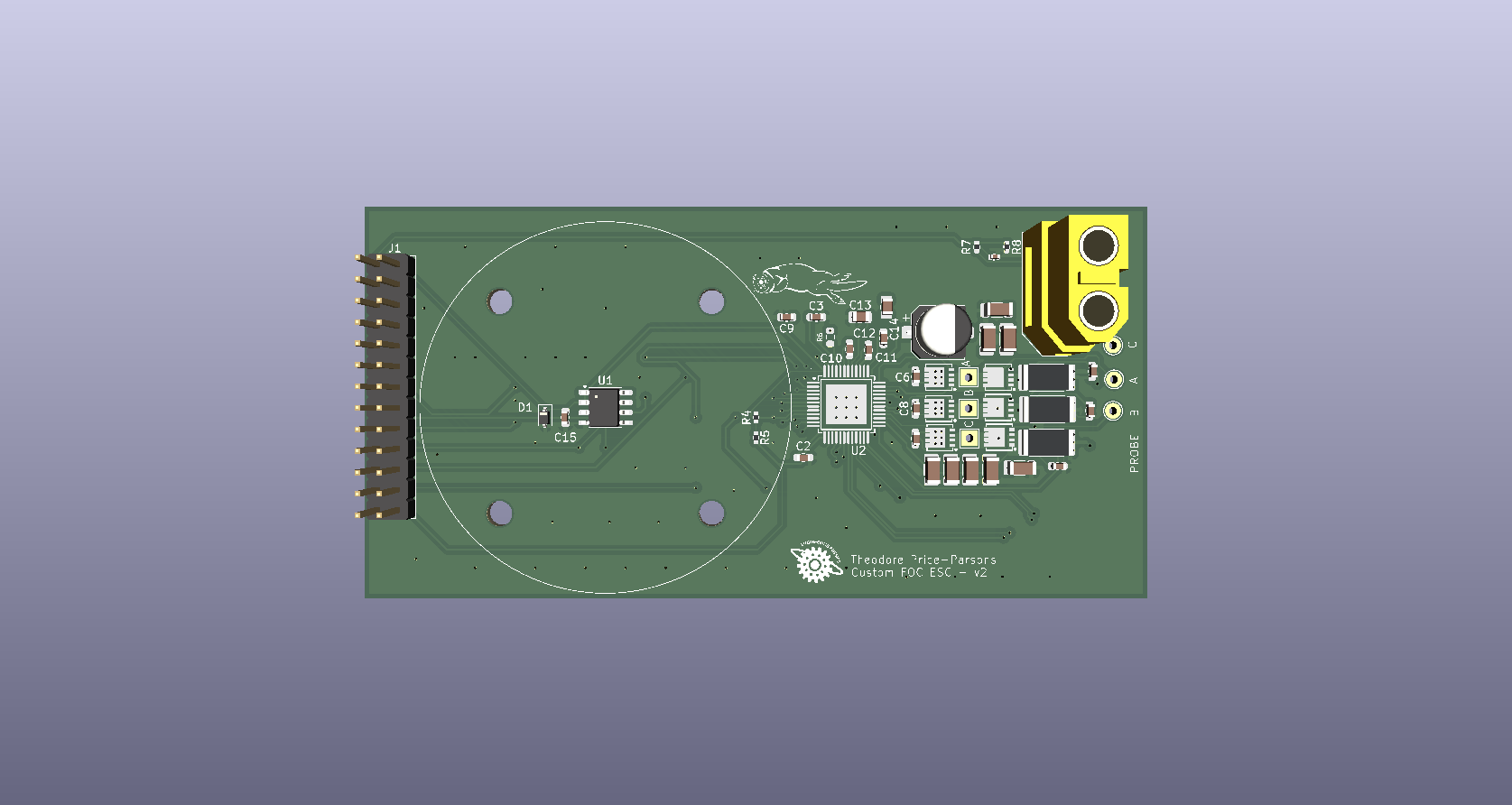
ESC is an open-source printed circuit board by TheodorePriceParsons, from the TheodorePriceParsons/Custom-FOC-ESC repository on GitHub. It is a 4-layer board of 99.1 × 49.5 mm with 56 parts on 49 nets, routed with 583 tracks and 174 vias.
It is built around the DRV8305NPHPR, MT6701CT-STD and AON7544. Its parts include 25 capacitors, 8 resistors, 6 transistors, 2 ICs and 2 connectors. It belongs with the robots and motor control boards of this library.


A field-oriented-control motor controller designed from scratch: a 4-layer power board, STM32G474 firmware with cascaded current and speed loops, and an automated hardware-in-the-loop test bench that verifies the drive against written requirements.
https://github.com/user-attachments/assets/c9957159-f915-4ab0-a1e7-d9c9039c102c
First closed-loop FOC spin (Oct 2026); kept for sentimental value.
Results are published here from the test bench with python bench/publish.py <run folder>.
 NUCLEO-G474RE                                        ESC board                    GM4108H motor
 ┌──────────────────────────────────────────┐        ┌─────────────────────┐
 │ HRTIM ── 3 x PWM (center-aligned) ───────┼──────▶ │ DRV8305 → 3 half-   │ ───▶ phases A/B/C
 │   └─ ADC trigger at PWM center           │        │ bridges (AON7544)   │
 │ ADC1 + DMA ◀── 3 shunt amplifiers ───────┼─────── │ 5 mΩ shunts, 40 V/V │
 │ SPI3 (shared bus) ◀──────────────────────┼─────── │ DRV8305 config/stat │
 │                  ◀──────────────────────┼─────── │ MT6701 encoder (SSI)│ ◀── magnet on rotor
 │ foc_isr() @ 10.38 kHz                    │        └─────────────────────┘
 │ LPUART1 ◀──▶ test bench (PC)             │
 └──────────────────────────────────────────┘
Each control period:
The derivations, including the PI design by pole-zero cancellation, the speed loop design and the expected step responses, are in docs/control-math.md.
The bench (in bench/) drives the ESC over UART from Python:
python bench/run_bench.py --port COM5 --tune-currentbench/spec.py; each test runs N times and reports mean ± std.--sim), and the metric code has unit tests.Details: bench/README.md, wire protocol: bench/PROTOCOL.md.
| Gate driver | TI DRV8305, 3-PWM mode, SPI configuration, integrated current-sense amplifiers (40 V/V) |
| Power stage | AON7544 N-channel MOSFETs, 3 half-bridges |
| Current sensing | 5 mΩ low-side shunts on all three phases (±8 A sense range), sampled at PWM center |
| Position | MT6701 14-bit magnetic encoder over SSI, sharing one SPI bus with the DRV8305 |
| Stackup | 4 layers: power stage, solid ground, PVDD plane, signals |
| Power | 3S LiPo (12 V), XT60; 2 mm bullet connectors for swappable motor leads |
| Controller | NUCLEO-G474RE (Cortex-M4F, 170 MHz) |
| Motor | GM4108H-120T gimbal motor, 11 pole pairs |
KiCad projects are in hardware/ and motor mounts in mechanical/.
Four wiring and configuration mistakes took most of the bring-up time:
| Folder | Contents |
|---|---|
firmware/ | STM32CubeIDE project. Control code in App/foc/, drivers in App/drivers/, bench interface in App/bench/ |
hardware/ | KiCad projects for each board revision |
mechanical/ | Motor and encoder mounts (STEP) |
bench/ | Automated test bench, requirements, reports |
docs/ | Control math and figures |
| Qty | Value | Footprint | References |
|---|---|---|---|
| 8 | 10uF | Capacitor_SMD:C_1206_3216Metric | C16, C17, C18, C19, C20, C21, C22, C23 |
| 7 | 1uF | Capacitor_SMD:C_0603_1608Metric | C1, C2, C3, C6, C8, C9, C12 |
| 6 | AON7544 | GS_MOSFETs:DFN-8_L3.3-W3.3-P0.65-BL-2 | Q1, Q2, Q3, Q4, Q5, Q6 |
| 3 | 1000 pF | Capacitor_SMD:C_0603_1608Metric | C4, C5, C7 |
| 3 | 10k | Resistor_SMD:R_0402_1005Metric | R4, R5, R7 |
| 3 | 5mOhm | Resistor_SMD:R_2512_6332Metric | R1, R2, R3 |
| 3 | NetTie_2 | NetTie:NetTie-2_SMD_Pad0.5mm | NT1, NT2, NT3 |
| 2 | 0.047uF | Capacitor_SMD:C_0603_1608Metric | C10, C11 |
| 1 | 0.1uF | Capacitor_SMD:C_0603_1608Metric | C15 |
| 1 | 100 R | GS_Resistors:R_0603_1608Metric | R6 |
| 1 | 100uF | Capacitor_SMD:CP_Elec_6.3x5.9 | C24 |
| 1 | 1nF | Capacitor_SMD:C_0402_1005Metric | C25 |
| 1 | 2.2uF | Capacitor_SMD:C_0805_2012Metric | C14 |
| 1 | 3.3K | Resistor_SMD:R_0402_1005Metric | R8 |
| 1 | 4.7uF | Capacitor_SMD:C_0805_2012Metric | C13 |
| 1 | 6V, unidirectional | Diode_SMD:D_SOD-323 | D1 |
| 1 | Conn_01x02 | Connector_AMASS:AMASS_XT60-F_1x02_P7.20mm_Vertical | J2 |
| 1 | Conn_02x13_Odd_Even | Connector_PinHeader_2.54mm:PinHeader_2x13_P2.54mm_Vertical | J1 |
| 1 | DRV8305NPHPR | GS_Gate_Drivers:HTQFP-48_L7.0-W7.0-P0.50-LS9.0-BL-EP5.1 | U2 |
| 1 | LOGO | GM4108H_Motor_Mount:Otter_footprint1 | G*** |
| 1 | LOGO | GM4108H_Motor_Mount:ENPH | G*** |
| 1 | MT6701CT | Package_SO:SO-8_3.9x4.9mm_P1.27mm | U1 |
| 1 | P1 | TestPoint:TestPoint_THTPad_D2.0mm_Drill1.0mm | TP10 |
| 1 | P2 | TestPoint:TestPoint_THTPad_D2.0mm_Drill1.0mm | TP11 |
| 1 | P3 | TestPoint:TestPoint_THTPad_D2.0mm_Drill1.0mm | TP12 |
| 1 | PHASE 1 | TestPoint:TestPoint_THTPad_2.0x2.0mm_Drill1.0mm | TP1 |
| 1 | PHASE 2 | TestPoint:TestPoint_THTPad_2.0x2.0mm_Drill1.0mm | TP2 |
| 1 | PHASE 3 | TestPoint:TestPoint_THTPad_2.0x2.0mm_Drill1.0mm | TP3 |
The 55 most common of 56 parts.


TobleMiner/DC-UPS
A small DC UPS, designed to keep small appliances like consumer network equipment running during power outages

VimDrones/AM32_esc_development_board
Open Source AM32 ESC development board

chipsalliance/rocket-pcb
PCB libraries and templates for rocket-chip based FPGA/ASIC designs

LimesKey/parsnip-node
A portable LoRa communicator. Custom 4-layer PCB (ESP32-S3 + E22P-915M30S LoRa + NEO-M9N GNSS), designed in KiCad for 915 MHz.

cr1tbit/i2current
The Raison d'être of this board is to be a powerful, extensible, and affordable replacement for hotglueing a random powerbank into your next portable small-scale electronic project.

tudsat-rocket/stigma
core board and mission board for a new flight computer

RainbowLabsDE/LightInstallationController
PCB and Firmware of our first universal RGB light installation controller.
It measures 99.1 × 49.5 mm and has 4 copper layers, 1.6 mm thick.
56 parts, built around the DRV8305NPHPR, MT6701CT-STD and AON7544. The full list of its parts is on this page, with links to each part's symbol and footprint where PCBKit's library has them.
From the TheodorePriceParsons/Custom-FOC-ESC repository on GitHub, at the commit this page was made from: the board is hardware/ESC_FINAL_rev/ESC.kicad_pcb and its schematic hardware/ESC_FINAL_rev/ESC.kicad_sch. PCBKit opens the board in the browser, with nothing to install.
Its repository states no licence, so its author keeps all rights: ask TheodorePriceParsons before reusing the design.