2 layers30 × 18.8 mm
Water sample collector iot system
TheTesla/HTW-Water-Sample-Collector
Coolecting water samples during flood events and send notify message
10 parts

 TheTesla/HTW-Water-Sample-Collector
Coolecting water samples during flood events and send notify message
Water sample collector iot main is an open-source printed circuit board by TheTesla, from the TheTesla/HTW-Water-Sample-Collector repository on GitHub. It is a 2-layer board of 80 × 47.5 mm with 81 parts on 71 nets, routed with 283 tracks and 6 vias.
It is built around the STLQ020C33R, RMCF0805FT10K0 and CL21B104KACNNNC, with the 1N4148W, RMCF0805JT330R and DMP3098L-7-ES among its other parts. Its parts include 37 resistors, 12 capacitors, 8 connectors, 7 diodes and 6 transistors. It belongs with the home automation and IoT boards of this library.


This IoT sensor module sends a notification over the LoRa network, when the water sample collector is full.
Only, if the water level is high enough during a flood event, it collects water. This IoT solution prevents unnecessary work driving to the collector to check the state manually.
The open source solution for the monitoring of water sample collectors features extendability with additional sensors like water level or conductance logging. It enables low-cost, low-entry barrier flexible IoT monitoring without the need of proprietary tools for usage and development.
One advantage is the optimization for battery efficiency. A standby current consumption below 10 µA at an operating voltage around 3.6 V of a single AA-size Tadiran SL-360 Li-SOCl2 primary cell with 2.4 Ah capacity allows up to 20 years operation on one battery cell.
The structure of this Open Source Hardware repository is based on the OSH-Design-Guideline. It is the root repository for all parts used to build the measurement arm.
The following files are the most important subset needed to build and use the measurement arm:
.
└─┬ src/                                     # git modules/dependencies root
  ├─┬ software/                              # software for the server
  │ └── wsciot/                              # LoRa to email msg. forwarding server
  ├─┬ firmware/                              # runs on the Arduino MKR WAN 1310
  │ ├── check_clock/                         # debugging the RTC
  │ ├── check_connection/                    # debugging LoRa communication
  │ └── keep_alive/                          # the production firmware keep alive msg.
  ├─┬ mech/                                  # 3d printable mounting elements
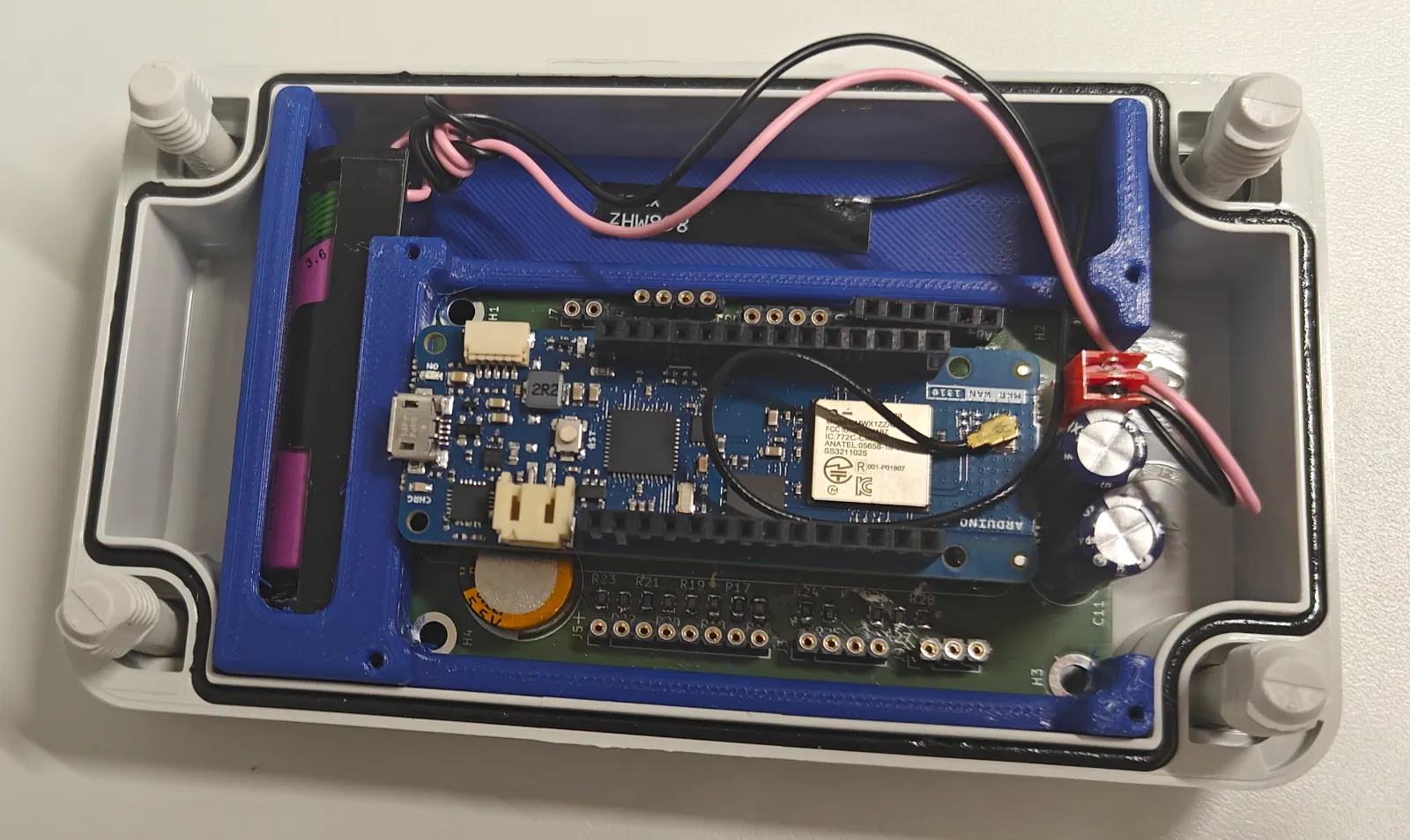
  │ └── wsciot-mountingframe/                # the blue frame shown in the main photo
  └─┬ elec/                                  # electronic parts/pcbs
    ├── water_sample_collector_iot_main/     # main pcb, 1 piece needed
└── water_sample_collector_iot_system/ # wiring diagram of the connections of the peripheral components around the water_sample_collector_iot_mainStefan Helmert stefan.helmert@htw-dresden.de Hochschule für Technik und Wirtschaft Dresden -- University of Applied Sciences Friedrich-List-Platz 1 01069 Dresden Germany
This work was funded by Volkswagen Foundation under grant number 9C858.
Following components are needed:
The main LoRa IoT module is fully assembled with battery, antenna, Aduino on the main board and the blue mounting frame:
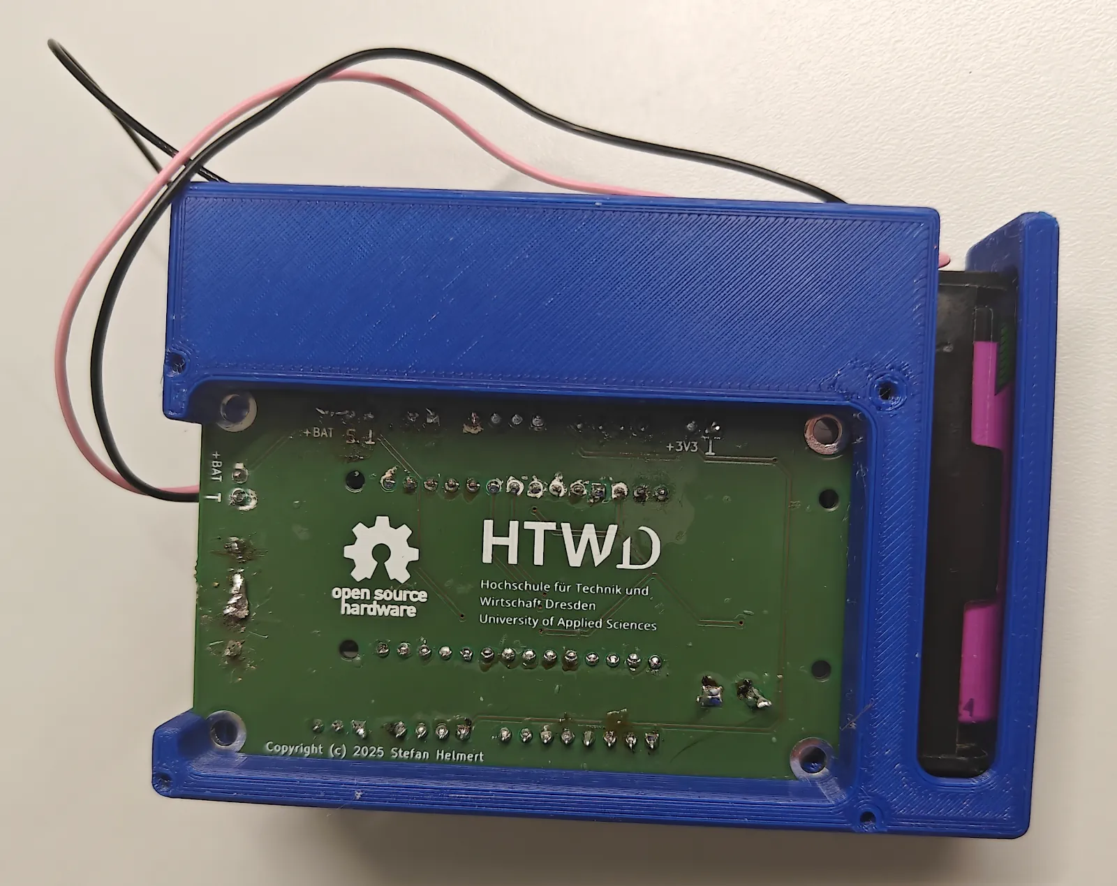
The back side:
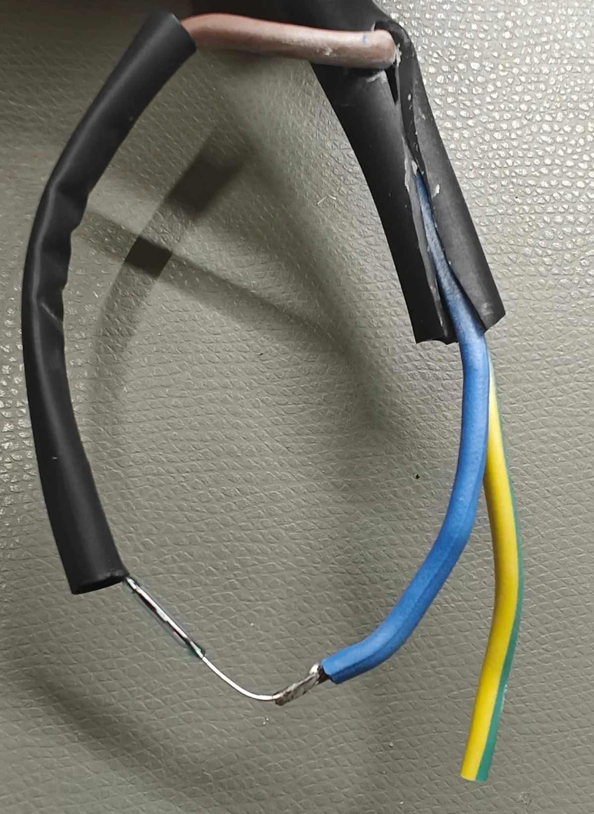
This reed switch must be placed on top of the water sample collector head to be able to register the valve state:
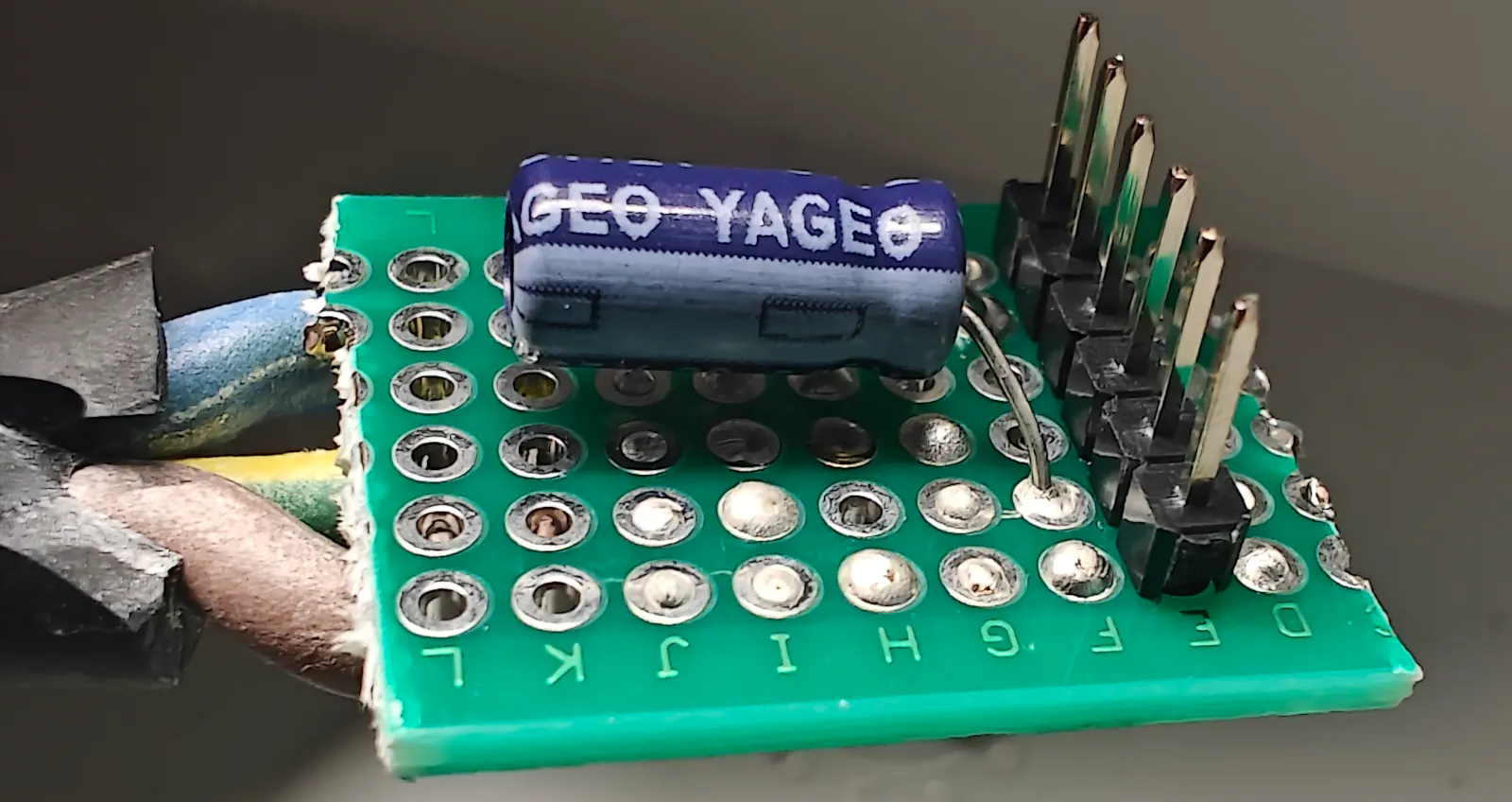
The 6-pin connector of the cable, where the reed switch is attached, must be plugged into the corresponding socket at the main board:
| Qty | Value | Footprint | References |
|---|---|---|---|
| 25 | 10k | Resistor_SMD:R_0805_2012Metric | R10, R11, R12, R13, R14, R16, R17, R18, R19, R20, R21, R22, R23, R24, R25, R26 +9 |
| 5 | 100n | Capacitor_SMD:C_0805_2012Metric | C4, C5, C6, C7, C10 |
| 5 | 1N4148W | Diode_SMD:D_SOD-123 | D3, D4, D5, D6, D7 |
| 5 | 330 | Resistor_SMD:R_0805_2012Metric | R1, R2, R3, R33, R34 |
| 4 | DMP3098L | Package_TO_SOT_SMD:SOT-23 | Q1, Q2, Q3, Q6 |
| 4 | MountingHole_Pad | MountingHole:MountingHole_3.2mm_M3_DIN965_Pad | H1, H2, H3, H4 |
| 3 | 680k | Resistor_SMD:R_0805_2012Metric | R6, R7, R15 |
| 3 | Conn_01x04_Socket | Connector_PinSocket_2.54mm:PinSocket_1x04_P2.54mm_Vertical | J2, J3, J4 |
| 2 | 1u | Capacitor_SMD:C_0805_2012Metric | C8, C9 |
| 2 | 2M2 | Resistor_SMD:R_0805_2012Metric | R4, R5 |
| 2 | 2k2 | Resistor_SMD:R_0805_2012Metric | R8, R9 |
| 2 | 3.3 | Capacitor_THT:CP_Radial_D8.0mm_P3.50mm | C11, C12 |
| 2 | BC856 | Package_TO_SOT_SMD:SOT-23 | Q4, Q5 |
| 2 | BZV55C5V6 | Diode_SMD:D_MiniMELF | D1, D2 |
| 2 | Conn_01x02_Socket | Connector_PinSocket_2.54mm:PinSocket_1x02_P2.54mm_Vertical | J7, J10 |
| 2 | Conn_01x03_Socket | Connector_PinSocket_2.54mm:PinSocket_1x03_P2.54mm_Vertical | J8, J9 |
| 1 | 10p | Capacitor_SMD:C_0603_1608Metric | C2 |
| 1 | 12p | Capacitor_SMD:C_0603_1608Metric | C1 |
| 1 | 220m | Capacitor_THT:CP_Radial_D14.0mm_P5.00mm | C3 |
| 1 | 32.768 kHz | Crystal:Crystal_SMD_MicroCrystal_CC7V-T1A-2Pin_3.2x1.5mm | Y1 |
| 1 | Arduino_MKR_WAN_1310_Socket | arduino-library:Arduino_MKR_FOX_1200_Socket | A1 |
| 1 | Battery_Cell | TE Connectivity:CONN2_640456-2_TEC | BT1 |
| 1 | Conn_01x08_Socket | Connector_PinSocket_2.54mm:PinSocket_1x08_P2.54mm_Vertical | J5 |
| 1 | LOGO | kicad_logos:htw_logo_x30 | G*** |
| 1 | MCP7940N-xSN | Package_SO:SOIC-8_3.9x4.9mm_P1.27mm | U1 |
| 1 | STLQ020-3.3 | Package_TO_SOT_SMD:SOT-353_SC-70-5 | U2 |
The 80 most common of 81 parts.
TheTesla/HTW-Water-Sample-Collector
Coolecting water samples during flood events and send notify message

ShahinKhalkhali/SportsVisionPro
System that brings fans closer to the game like never before. By integrating immersive VR technology with real-time player data, our solution offers a first-person perspective of live hockey, enhancing audience…

CU-Rocketry/flight_computer
Competition Flight Computer Module 25-26


Canterrain/bread-proof-monitor
A DIY monitor to help you get bread proofing correct every time.

mymy49/GM100
This is an open project created using Nuvoton's M467 MCU for use in gauges or meters.

avycado13/avyduino
My take on the classic Arduino UNO. Powered by the same chips, but using a USB-C socket.


It measures 80 × 47.5 mm and has 2 copper layers, 1.6 mm thick.
81 parts, built around the STLQ020C33R, RMCF0805FT10K0, CL21B104KACNNNC and 1N4148W. The full list of its parts is on this page, with links to each part's symbol and footprint where PCBKit's library has them.
From the TheTesla/HTW-Water-Sample-Collector repository on GitHub, at the commit this page was made from: the board is src/elec/water_sample_collector_iot_main/water_sample_collector_iot_main.kicad_pcb and its schematic src/elec/water_sample_collector_iot_main/water_sample_collector_iot_main.kicad_sch. PCBKit opens the board in the browser, with nothing to install.
Its repository states no licence, so its author keeps all rights: ask TheTesla before reusing the design.