2 layers31.5 × 31.5 mm
Sensors
TheFlocke/rc-buggy
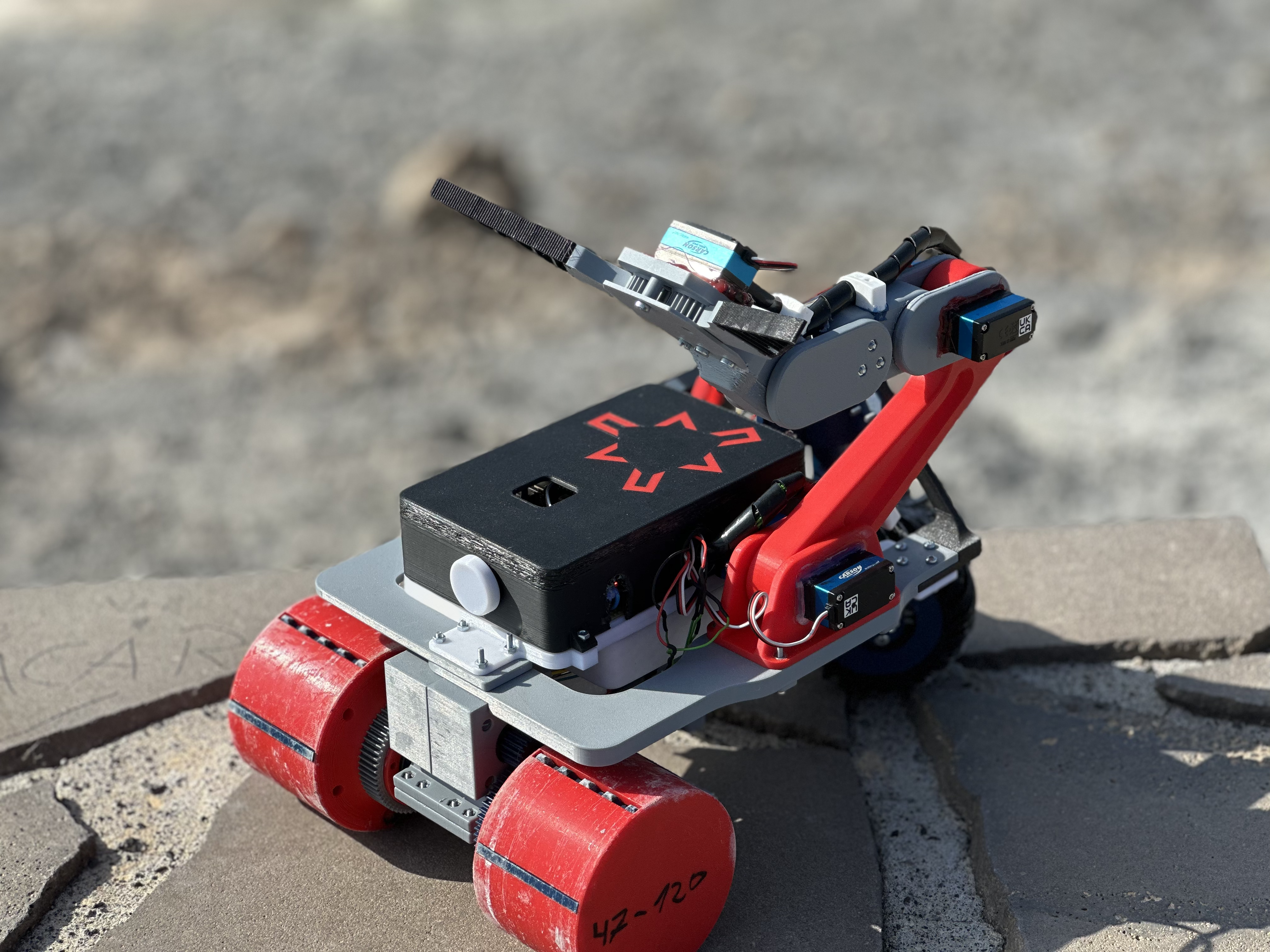
Autonomous rover with BLE control and robotic arm, built for a DLR high school competition.
16 partsGPL-3.0

 TheFlocke/rc-buggy
Autonomous rover with BLE control and robotic arm, built for a DLR high school competition.
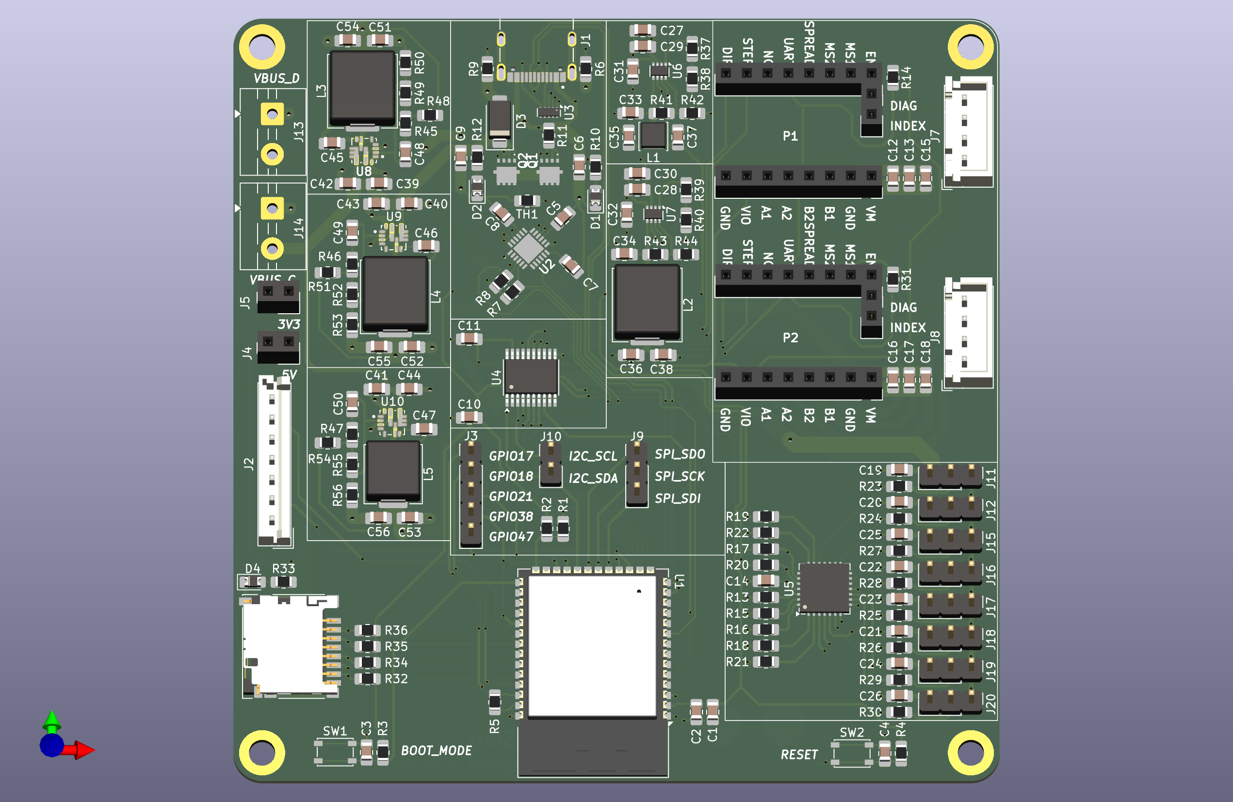
RC Buggy is an open-source printed circuit board by TheFlocke, from the TheFlocke/rc-buggy repository on GitHub, published under the GPL-3.0 licence. It is a 4-layer board of 93.5 × 94.5 mm with 162 parts on 169 nets, routed with 1,420 tracks and 204 vias.
It is built around the ESP32-S3-WROOM-1-N8, TPS56637RPAR and TPS62933DRL, with the PCA9685BS, BME680 and TPD4E05U06DQAR among its other parts. Its parts include 56 capacitors, 56 resistors, 22 connectors, 10 ICs and 5 inductors. It belongs with the robots and motor control boards and the ESP32 boards of this library.


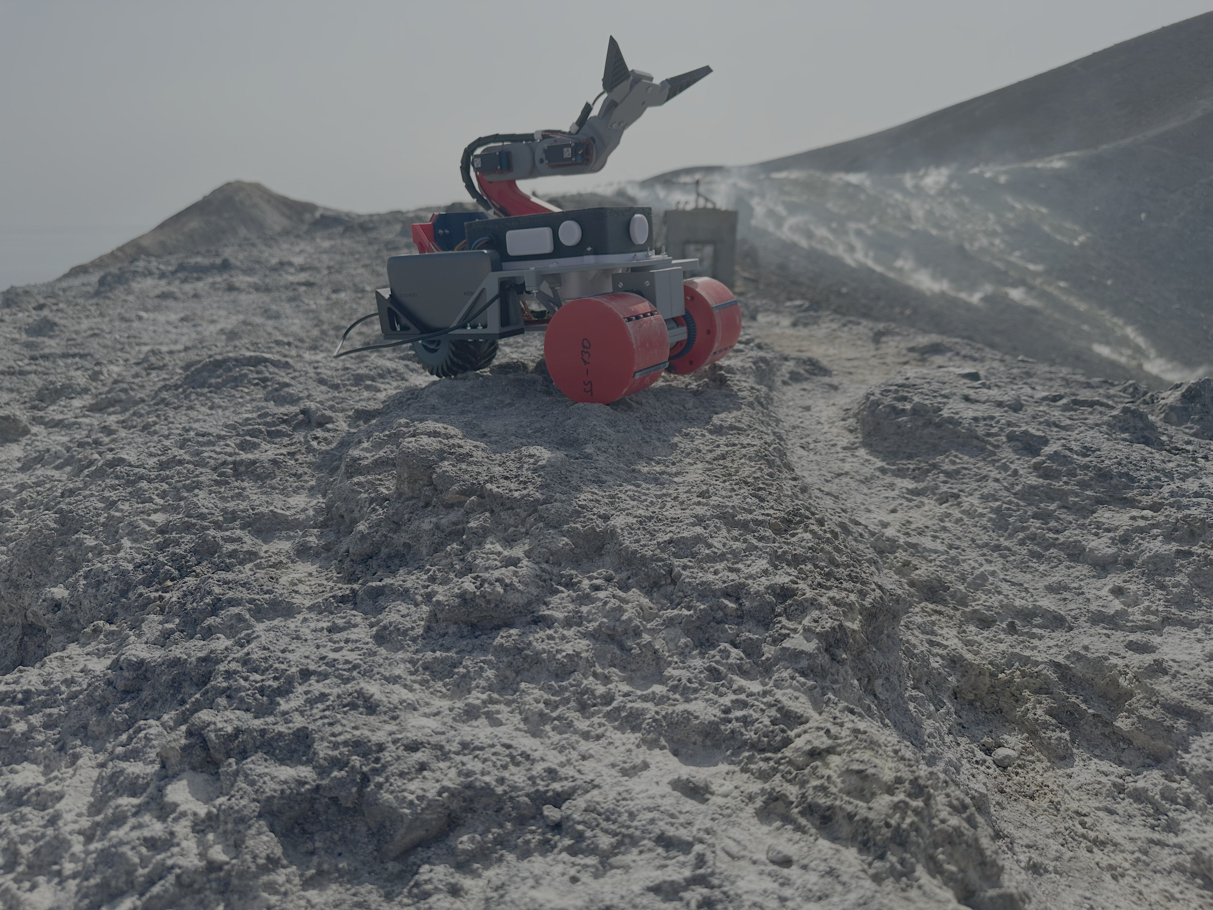
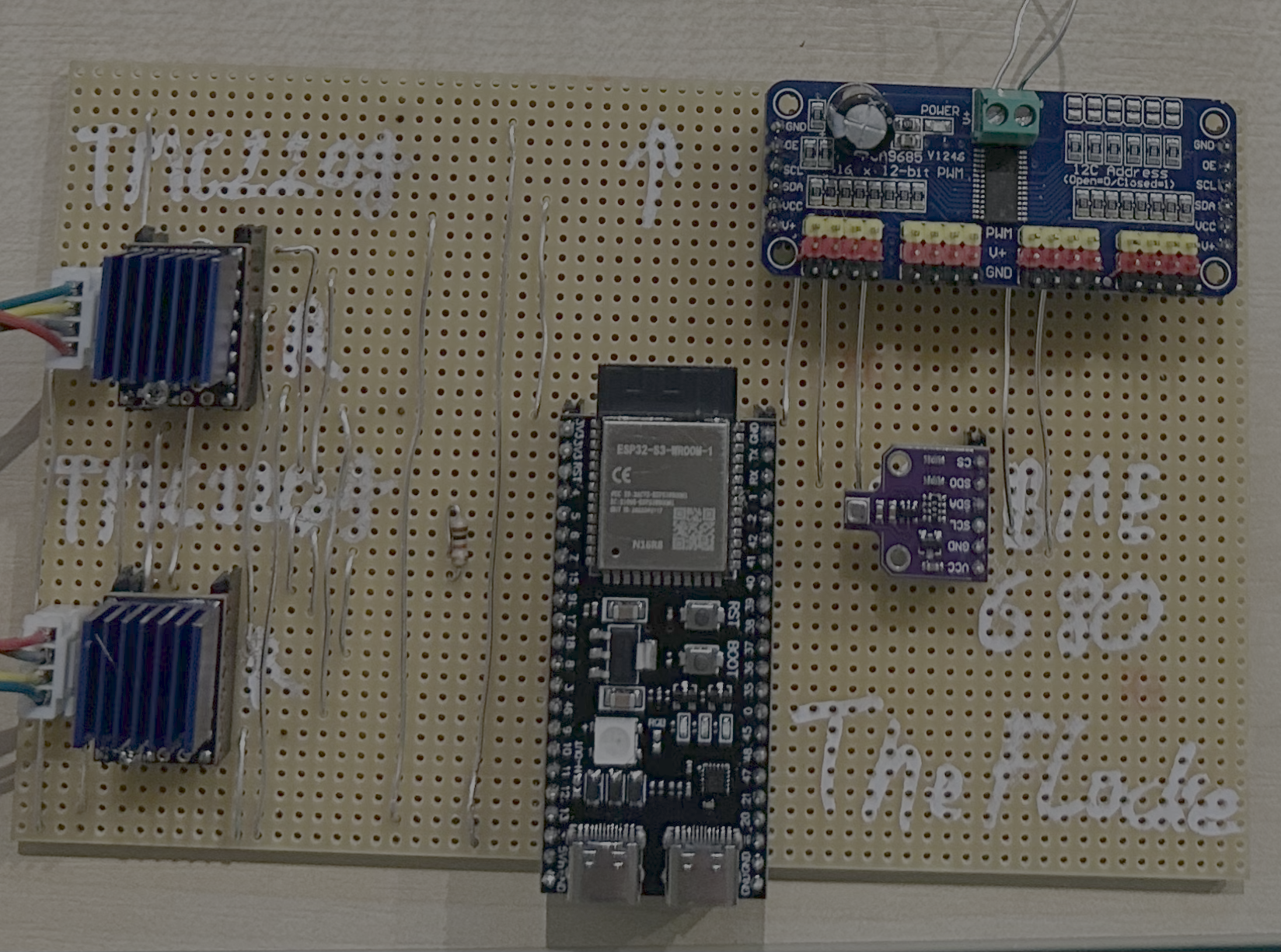
This project was developed as part of a high school competition organized by the German Aerospace Center (DLR). The challenge: design and build a rover capable of:
To enable wireless control from any BLE-capable device, I developed:
The foundation for the code was a project from my teacher, which I significantly modified and expanded. While I focused on electronics/software ⚡️, my teammates handled mechanical engineering ⚙️.
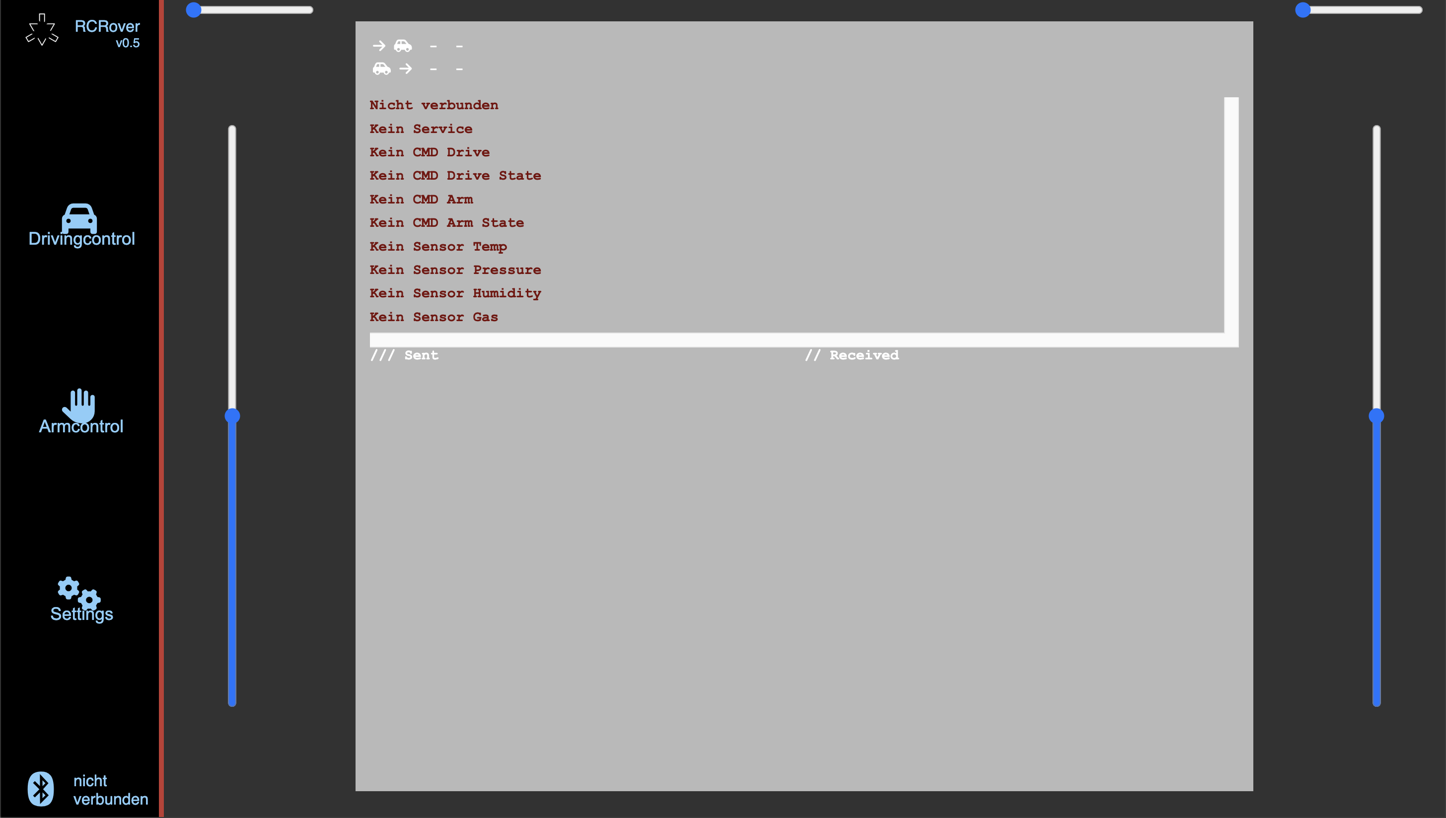
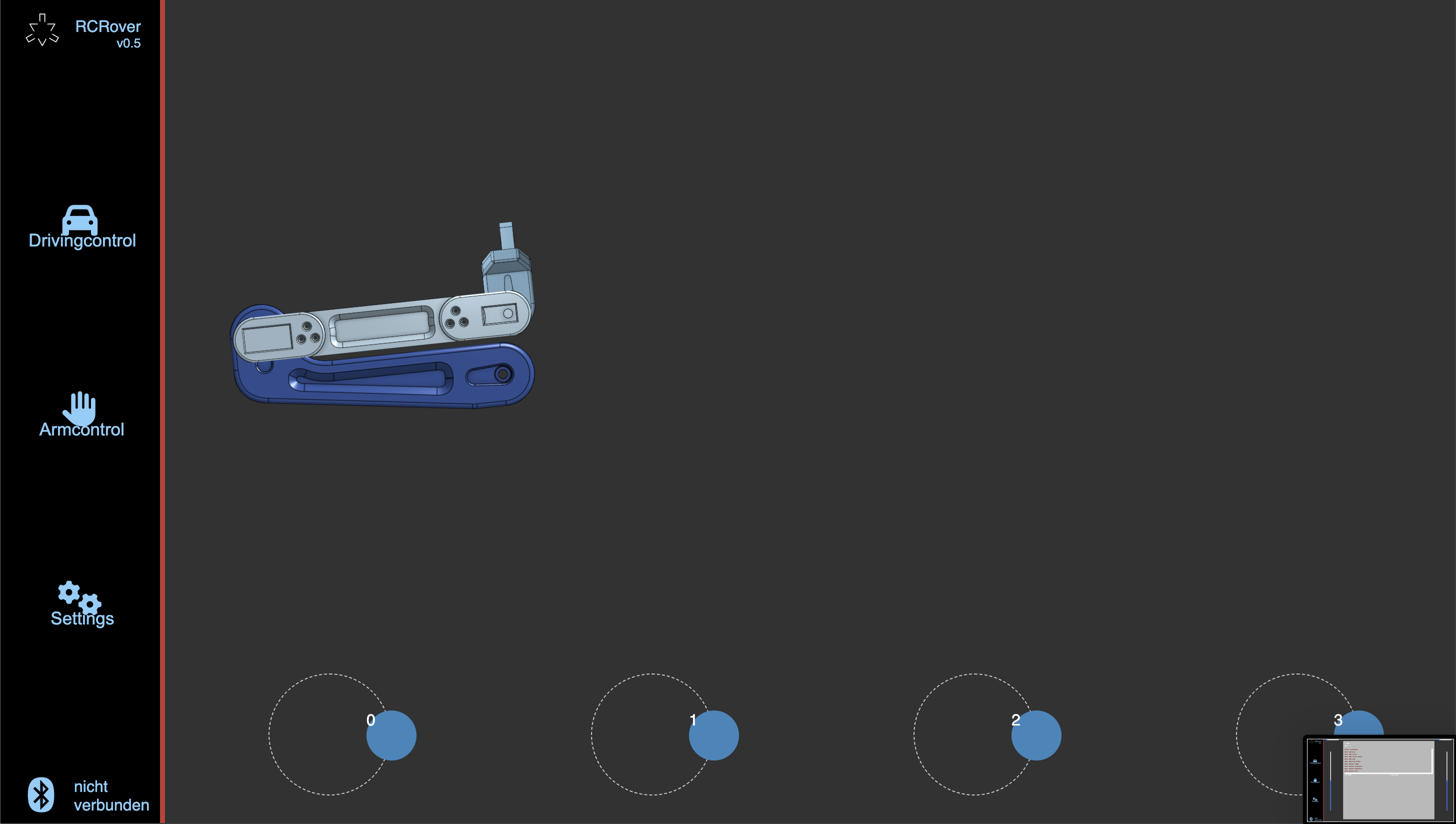
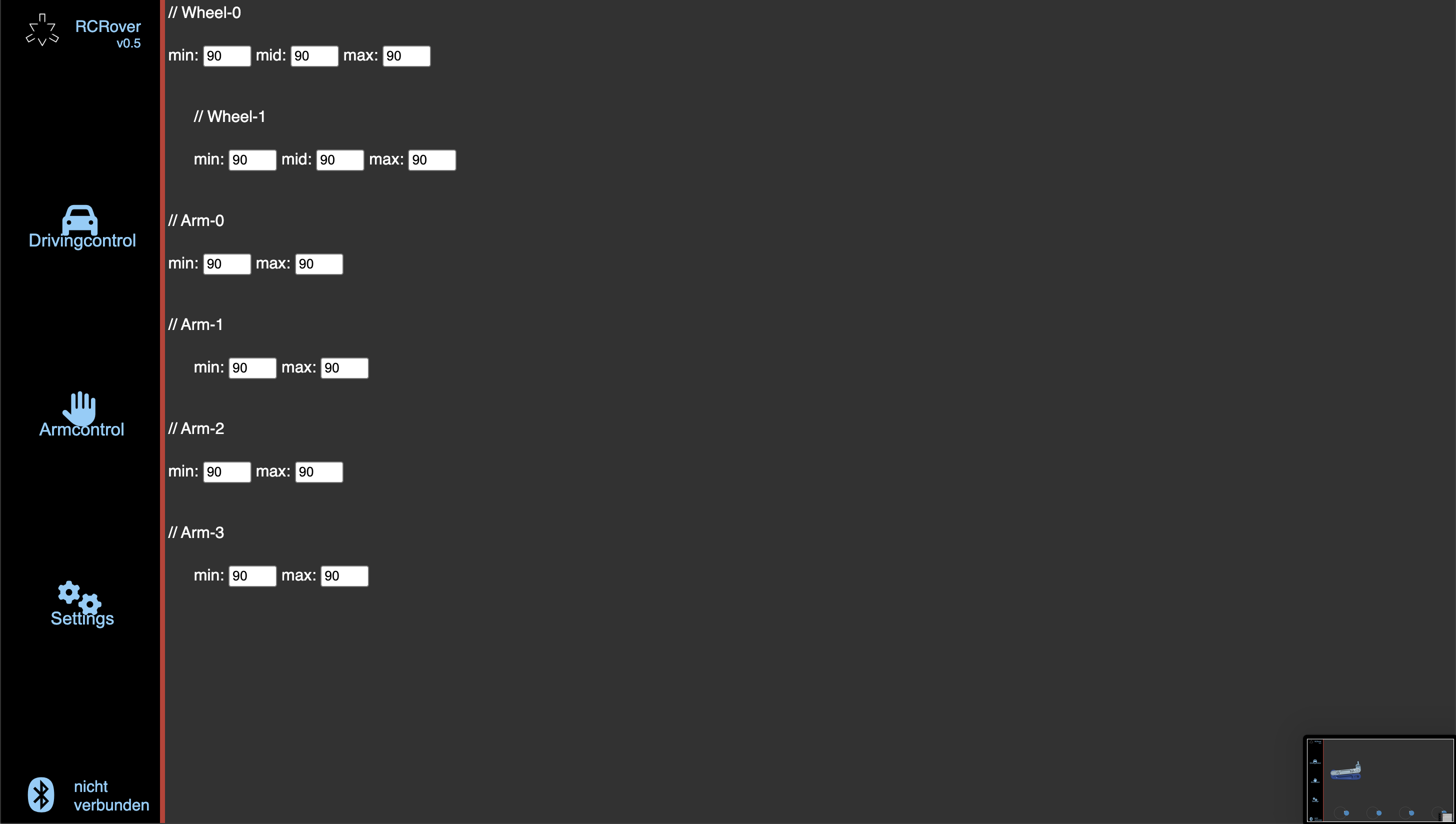
You’ll need VS Code or CLion with the PlatformIO extension.
See the Links section below for tutorials.
Clone or download this repository and open it in your chosen IDE.
ESP32ble.hUpload the code to your ESP32 device.
Use nRF Connect or similar BLE apps to verify data transmission.
| Qty | Value | Footprint | References |
|---|---|---|---|
| 30 | 10k | Resistor_SMD:R_0805_2012Metric_Pad1.20x1.40mm_HandSolder | R1, R2, R3, R10, R12, R13, R14, R15, R16, R17, R18, R19, R20, R21, R22, R31 +14 |
| 16 | 100nF | Capacitor_SMD:C_0805_2012Metric_Pad1.18x1.45mm_HandSolder | C5, C7, C13, C15, C17, C18, C19, C20, C21, C22, C23, C24, C25, C26, C33, C34 |
| 14 | 10uF | Capacitor_SMD:C_0805_2012Metric_Pad1.18x1.45mm_HandSolder | C2, C6, C9, C14, C27, C28, C29, C30, C39, C40, C41, C42, C43, C44 |
| 10 | 22uF | Capacitor_SMD:C_0805_2012Metric_Pad1.18x1.45mm_HandSolder | C35, C36, C37, C38, C51, C52, C53, C54, C55, C56 |
| 8 | 0u1F | Capacitor_SMD:C_0805_2012Metric_Pad1.18x1.45mm_HandSolder | C1, C3, C4, C10, C11, C45, C46, C47 |
| 8 | 220 | Resistor_SMD:R_0805_2012Metric_Pad1.20x1.40mm_HandSolder | R23, R24, R25, R26, R27, R28, R29, R30 |
| 4 | 5k1 | Resistor_SMD:R_0805_2012Metric_Pad1.20x1.40mm_HandSolder | R6, R7, R8, R9 |
| 4 | MountingHole_Pad | MountingHole:MountingHole_3.2mm_M3_DIN965_Pad_TopBottom | H1, H2, H3, H4 |
| 3 | 100pF | Capacitor_SMD:C_0805_2012Metric_Pad1.18x1.45mm_HandSolder | C48, C49, C50 |
| 3 | 20k | Resistor_SMD:R_0805_2012Metric_Pad1.20x1.40mm_HandSolder | R45, R46, R47 |
| 3 | 3u3H | Inductor_SMD:L_APV_APH0850 | L2, L3, L4 |
| 3 | 49k9 | Resistor_SMD:R_0805_2012Metric_Pad1.20x1.40mm_HandSolder | R48, R51, R54 |
| 3 | LED | Diode_SMD:D_0805_2012Metric_Pad1.15x1.40mm_HandSolder | D1, D2, D4 |
| 3 | TPS56637RPAR | Footprints:CONV_TPS56637RPAR | U8, U9, U10 |
| 2 | 100uF | Capacitor_SMD:C_0805_2012Metric_Pad1.18x1.45mm_HandSolder | C12, C16 |
| 2 | 33nF | Capacitor_SMD:C_0805_2012Metric_Pad1.18x1.45mm_HandSolder | C31, C32 |
| 2 | 73k2 | Resistor_SMD:R_0805_2012Metric_Pad1.20x1.40mm_HandSolder | R49, R52 |
| 2 | AON7262E | Footprints:AON7262E | Q1, Q2 |
| 2 | PW_IO_bak | TerminalBlock:TerminalBlock_MaiXu_MX126-5.0-02P_1x02_P5.00mm | J13, J14 |
| 2 | SW_Push | Button_Switch_SMD:SW_SPST_PTS810 | SW1, SW2 |
| 2 | TMC2209_Socket | custom:TMC2209_Socket | P1, P2 |
| 2 | TPS62933 | Package_TO_SOT_SMD:SOT-583-8 | U6, U7 |
| 1 | 100V | Diode_SMD:D_SMA | D3 |
| 1 | 100k | Resistor_SMD:R_0805_2012Metric_Pad1.20x1.40mm_HandSolder | R55 |
| 1 | 10m | Resistor_SMD:R_0805_2012Metric_Pad1.20x1.40mm_HandSolder | R11 |
| 1 | 15 | Resistor_SMD:R_0805_2012Metric_Pad1.20x1.40mm_HandSolder | R33 |
| 1 | 1k | Resistor_SMD:R_0805_2012Metric_Pad1.20x1.40mm_HandSolder | R5 |
| 1 | 1uF | Capacitor_SMD:C_0805_2012Metric_Pad1.18x1.45mm_HandSolder | C8 |
| 1 | 2u4H | Inductor_SMD:L_APV_ANR3015 | L1 |
| 1 | 31k6 | Resistor_SMD:R_0805_2012Metric_Pad1.20x1.40mm_HandSolder | R41 |
| 1 | 4u3H | Inductor_SMD:L_APV_APH0650 | L5 |
| 1 | 52k3 | Resistor_SMD:R_0805_2012Metric_Pad1.20x1.40mm_HandSolder | R43 |
| 1 | BME680 | Connector_JST:JST_EH_B7B-EH-A_1x07_P2.50mm_Vertical | J2 |
| 1 | ESP32-S3-WROOM-1 | RF_Module:ESP32-S3-WROOM-1 | U1 |
| 1 | GPIO | Connector_PinHeader_2.54mm:PinHeader_1x05_P2.54mm_Vertical | J3 |
| 1 | I2C | Connector_PinHeader_2.54mm:PinHeader_1x02_P2.54mm_Vertical | J10 |
| 1 | Micro_SD_Card_Det_Hirose_DM3AT | Connector_Card:microSD_HC_Hirose_DM3D-SF | J6 |
| 1 | NTC-10k | Resistor_SMD:R_0805_2012Metric_Pad1.20x1.40mm_HandSolder | TH1 |
| 1 | PCA9685BS | Package_DFN_QFN:QFN-28-1EP_6x6mm_P0.65mm_EP4.25x4.25mm | U5 |
| 1 | PW_3V3 | Connector_PinSocket_2.54mm:PinSocket_1x02_P2.54mm_Vertical | J5 |
| 1 | PW_5V | Connector_PinSocket_2.54mm:PinSocket_1x02_P2.54mm_Vertical | J4 |
| 1 | SPI | Connector_PinHeader_2.54mm:PinHeader_1x03_P2.54mm_Vertical | J9 |
| 1 | Servo 0 | Connector_PinHeader_2.54mm:PinHeader_1x03_P2.54mm_Vertical | J11 |
| 1 | Servo 1 | Connector_PinHeader_2.54mm:PinHeader_1x03_P2.54mm_Vertical | J12 |
| 1 | Servo 2 | Connector_PinHeader_2.54mm:PinHeader_1x03_P2.54mm_Vertical | J17 |
| 1 | Servo 3 | Connector_PinHeader_2.54mm:PinHeader_1x03_P2.54mm_Vertical | J18 |
| 1 | Servo 4 | Connector_PinHeader_2.54mm:PinHeader_1x03_P2.54mm_Vertical | J15 |
| 1 | Servo 5 | Connector_PinHeader_2.54mm:PinHeader_1x03_P2.54mm_Vertical | J16 |
| 1 | Servo 6 | Connector_PinHeader_2.54mm:PinHeader_1x03_P2.54mm_Vertical | J19 |
| 1 | Servo 7 | Connector_PinHeader_2.54mm:PinHeader_1x03_P2.54mm_Vertical | J20 |
| 1 | Stepper_1 | Connector_JST:JST_XH_B4B-XH-A_1x04_P2.50mm_Vertical | J7 |
| 1 | Stepper_2 | Connector_JST:JST_XH_B4B-XH-A_1x04_P2.50mm_Vertical | J8 |
| 1 | TPD4E05U06DQA | Package_SON:USON-10_2.5x1.0mm_P0.5mm | U3 |
| 1 | TXS0108EPW | Package_SO:TSSOP-20_4.4x6.5mm_P0.65mm | U4 |
| 1 | TYPE-C-31-M-12 | Footprints:HRO_TYPE-C-31-M-12 | J1 |
| 1 | ~ | custom:AP33772 | U2 |
TheFlocke/rc-buggy
Autonomous rover with BLE control and robotic arm, built for a DLR high school competition.


misko/prompt2device
The separate vNext PCB skill and orchestrator package is available alongside the reference workflow below; existing projects keep their accepted toolchain until an explicit migration.


hugoNN1001/LattePanda-Mu-Custom-Carrier-Board
Personal project, work in progress - Learning digital high-speed PCB design by designing a custom carrier board for the LattePanda Mu - based on the reference design: https://github.com/LattePandaTeam/LattePanda-Mu

Keyaan-07/Hotplate
Check out the Project's files on KiCanvas(PCB and Heating element) and Onshape!

Keyaan-07/Zenith
A battery powered single board computer capable of running linux

It measures 93.5 × 94.5 mm and has 4 copper layers, 1.6 mm thick.
162 parts, built around the ESP32-S3-WROOM-1-N8, TPS56637RPAR, TPS62933DRL and PCA9685BS. The full list of its parts is on this page, with links to each part's symbol and footprint where PCBKit's library has them.
From the TheFlocke/rc-buggy repository on GitHub, at the commit this page was made from: the board is PCB/Mainboard/RC_Buggy.kicad_pcb and its schematic PCB/Mainboard/Connections.kicad_sch. PCBKit opens the board in the browser, with nothing to install.
Its repository publishes it under the GPL-3.0 licence: you may reuse it on that licence's terms (keep the author's notice, and for a copyleft licence share your changes alike).