
2 layers178 × 145 mm
Ultra DB X51 v1
ExploreEmbedded/8051_DevelopmentBoard
Design files and sample code for 8051 development Ultra Boards
145 parts70

 TeknoTrek/Fm-Transmitter7
This repository is part of the Teknotrek YouTube channel, where we share electronics projects. Find KiCad files for FM transmitters, voltage regulators, and more. Visit the Teknotrek YouTube channel https://www.youtube.com/channel/UCLOmh3PNItDSgDy55UoxpgQ for build videos and tutorials.
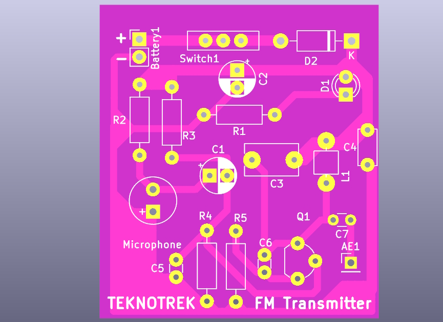
Fm Transmitter is an open-source printed circuit board by TeknoTrek, from the TeknoTrek/Fm-Transmitter repository on GitHub. It is a 2-layer board of 40 × 45 mm with 20 parts on 10 nets, routed with 417 tracks and 0 vias.
It is built around the BC548. Its parts include 7 capacitors, 5 resistors, 2 diodes, 1 transistor and 1 inductor.
This repository contains the KiCad project files for an FM Transmitter circuit operating in the 88 MHz – 108 MHz range. The design includes both the circuit schematic and the PCB layout, with a 3D model of the assembled board.
This FM transmitter is designed to broadcast audio signals using a microphone input. It covers the standard FM radio frequency range and is powered by a 9V battery. The circuit is based on a single transistor (BC548) and includes adjustable frequency tuning through a variable capacitor (C3).
You can watch the full build process of this FM transmitter on my YouTube channel Teknotrek. Click the link below to see how the circuit is assembled, soldered, and tested:
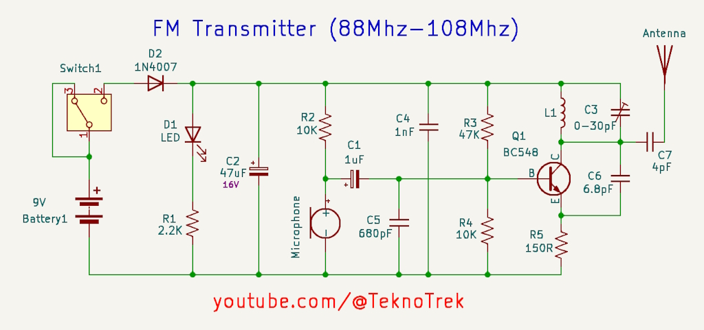
The circuit consists of the following key components:
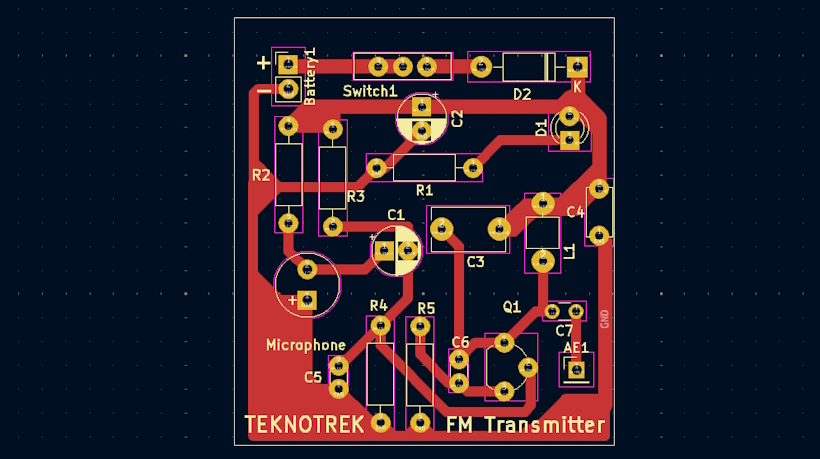
The PCB layout is designed to be compact, with clear labels for easy assembly. The board supports through-hole components for easier soldering.
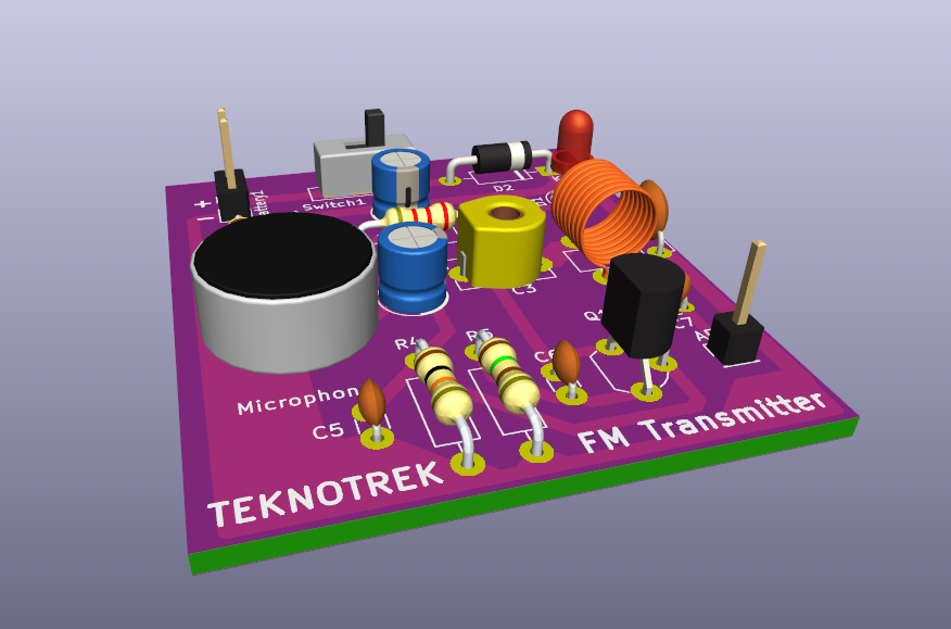
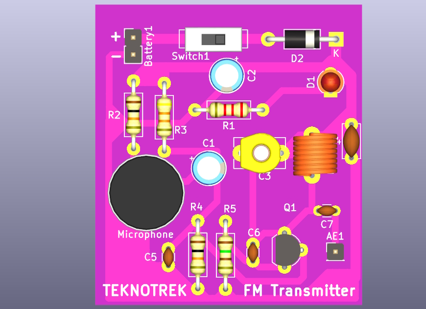
A 3D model of the assembled PCB is included to give you a better idea of how the final product will look.
Clone the repository:
git clone https://github.com/TeknoTrek/fm-transmitter.gitOpen the project in KiCad and review the schematic and PCB layout.
Assemble the components as per the schematic, solder them to the PCB, and tune the frequency using C3.
Attach a suitable antenna and power the transmitter using a 9V battery.
Let me know if you'd like to adjust any part of it!
| Qty | Value | Footprint | References |
|---|---|---|---|
| 2 | 10K | Resistor_THT:R_Axial_DIN0207_L6.3mm_D2.5mm_P10.16mm_Horizontal | R2, R4 |
| 1 | 0-30pF | YeniFoot:C_Disc_D6.0mm_W4.4mm_P6.00mm_x | C3 |
| 1 | 150R | Resistor_THT:R_Axial_DIN0207_L6.3mm_D2.5mm_P10.16mm_Horizontal | R5 |
| 1 | 1N4007 | Diode_THT:D_DO-41_SOD81_P10.16mm_Horizontal | D2 |
| 1 | 1nF | Capacitor_THT:C_Disc_D5.0mm_W2.5mm_P5.00mm | C4 |
| 1 | 1uF | Capacitor_THT:CP_Radial_D5.0mm_P2.50mm | C1 |
| 1 | 2.2K | Resistor_THT:R_Axial_DIN0207_L6.3mm_D2.5mm_P10.16mm_Horizontal | R1 |
| 1 | 47K | Resistor_THT:R_Axial_DIN0207_L6.3mm_D2.5mm_P10.16mm_Horizontal | R3 |
| 1 | 47uF | Capacitor_THT:CP_Radial_D5.0mm_P2.50mm | C2 |
| 1 | 4pF | Capacitor_THT:C_Disc_D3.0mm_W1.6mm_P2.50mm | C7 |
| 1 | 6.8pF | Capacitor_THT:C_Disc_D3.0mm_W1.6mm_P2.50mm | C6 |
| 1 | 680pF | Capacitor_THT:C_Disc_D3.0mm_W1.6mm_P2.50mm | C5 |
| 1 | 9V | Connector_PinHeader_2.54mm:PinHeader_1x02_P2.54mm_Vertical | Battery1 |
| 1 | Antenna | Connector_PinHeader_2.54mm:PinHeader_1x01_P2.54mm_Vertical | AE1 |
| 1 | BC548 | Package_TO_SOT_THT:TO-92_Wide | Q1 |
| 1 | L | YeniFoot:L_Axial_L7.0mm_D3.3mm_P6.00mm_Horizontal_Fastron | L1 |
| 1 | LED | LED_THT:LED_D3.0mm | D1 |
| 1 | Microphone | Buzzer_Beeper:MagneticBuzzer_Kingstate_KCG0601 | MK1 |
| 1 | SW | Button_Switch_THT:SW_Slide-03_Wuerth-WS-SLTV_10x2.5x6.4_P2.54mm | Switch1 |
ExploreEmbedded/8051_DevelopmentBoard
Design files and sample code for 8051 development Ultra Boards


DarcyJProjects/touchtone555
An open-source DIY, NE555-based analogue synthesizer - play notes with a stylus


clemarfolly/Microdigital-TK2000
Reprodução da PCB do TK-2000 da Microdigital, clone do Micro-Professor MPF-II

Danjovic/Soda-IDE
8 bit Compact Flash Interface for MSX computers

alvaroalea/all-spectrum-clones
Schematic of a 8bit computer, clone of Sinclair ZX Spectrum
It measures 40 × 45 mm and has 2 copper layers, 1.6 mm thick.
20 parts, built around the BC548. The full list of its parts is on this page, with links to each part's symbol and footprint where PCBKit's library has them.
From the TeknoTrek/Fm-Transmitter repository on GitHub, at the commit this page was made from: the board is FmTransmitter.kicad_pcb and its schematic FmTransmitter.kicad_sch. PCBKit opens the board in the browser, with nothing to install.
Its repository states no licence, so its author keeps all rights: ask TeknoTrek before reusing the design.