2 layers30 × 90 mm
TechWaveAudio MidiController
TechWave-Audio/TechWaveAudio-MidiControllerModule
TechWave Audio Midi Controller Module
41 parts4BSD-3-Clause
 TechWave-Audio/TechWaveAudio-MidiControllerModule4
TechWave Audio Midi Controller Module
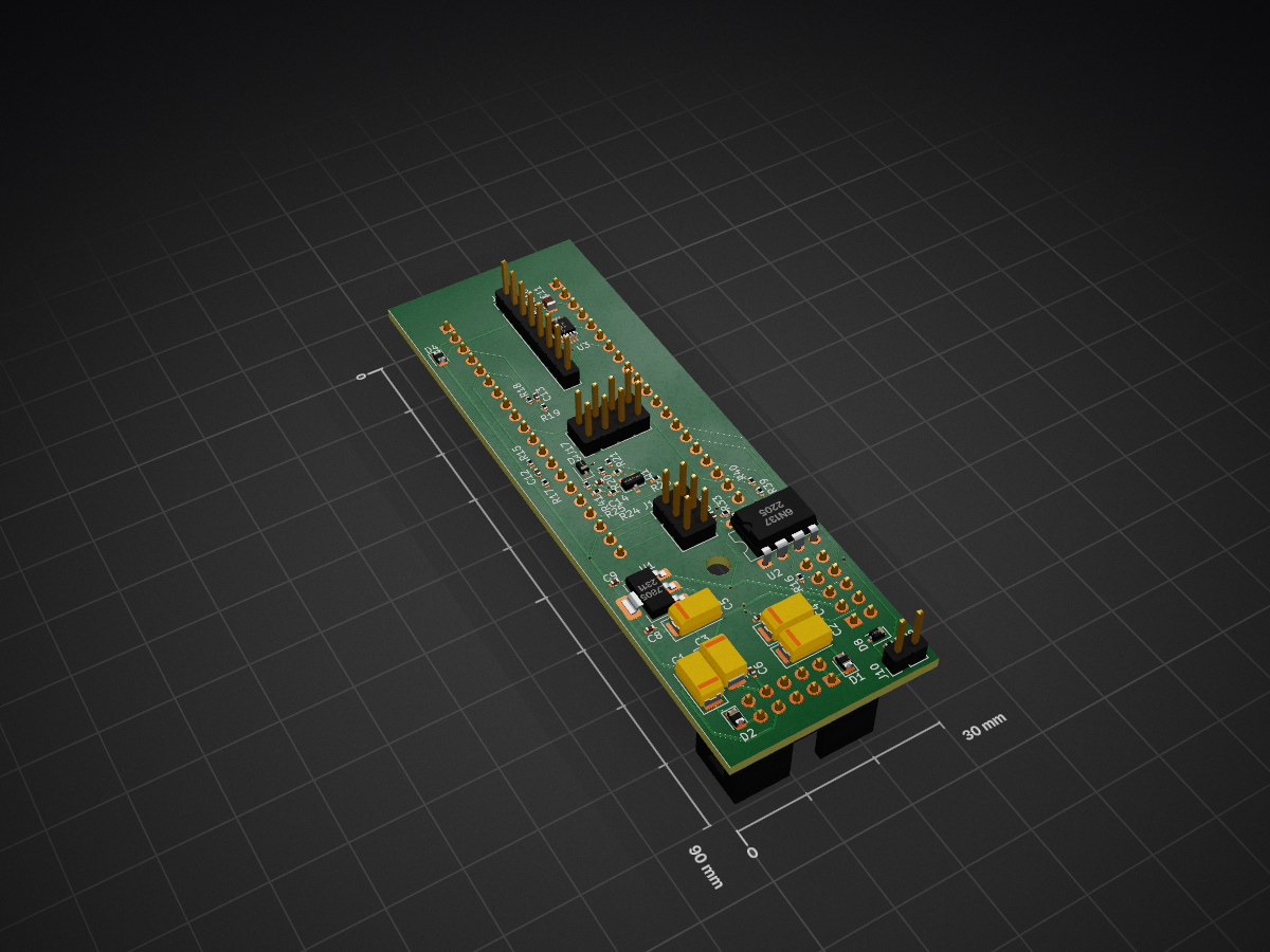
TechWaveAudio MCM-100-Main is an open-source printed circuit board by TechWave-Audio, from the TechWave-Audio/TechWaveAudio-MidiControllerModule repository on GitHub, published under the BSD-3-Clause licence. It is a 2-layer board of 30 × 90 mm with 50 parts on 58 nets, routed with 272 tracks and 11 vias.
It is built around the DAC7554IDGSR, L7805 and MMBT3904. Its parts include 17 resistors, 15 capacitors, 8 connectors, 5 diodes and 3 ICs. It belongs with the audio and music boards and the RP2350 boards of this library.


A monophonic MIDI controller Eurorack module using the Raspberry Pi Pico (RP2040).
Brought to you by TechWave Audio
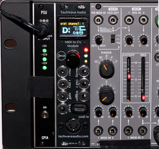

Clock output and can be routed as an aux and/or control output.Using the MCM-100-EX Expansion Module, you can also add an additional four assignable CV outputs.
This module requires a 10 pin (2x05 IDC connector) Eurorack power connection.
Be certain when you plug the connector in that the orientation is the correct way, with the -12v line (usually with the red stripe) on the left when looking at the rear of the module.
On startup, you should see the boot screen with the current version:
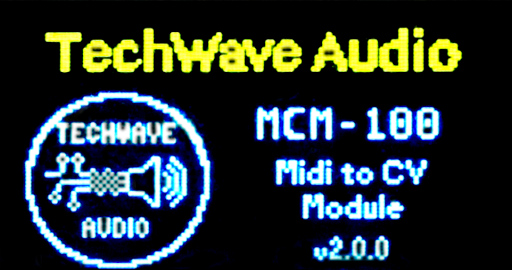
The note and clock LEDs should turn on and off a few times before the dashboard screen is shown and the module is ready to be used.
The user manual can be found on the TechWave Audio website.
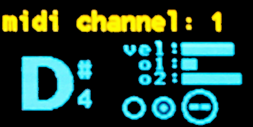
The dashboard shows the status of the current MIDI channel that it is listening on, as well as various outputs:
vel: The current velocity (corresponding to 0v to +10/+5v)o1: The current Out 1 value (corresponding to 0v to +10/+5v)o2: The current Out 2 value (corresponding to 0v to +10/+5v)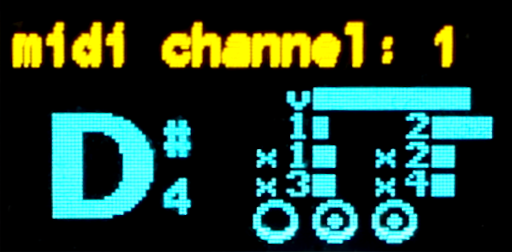
If the MCM-100-EX expansion module is attached, additionally it will show:
x1: The current Out X1 value (corresponding to 0v to +10/+5v)x2: The current Out X2 value (corresponding to 0v to +10/+5v)x3: The current Out X3 value (corresponding to 0v to +10/+5v)x4: The current Out X4 value (corresponding to 0v to +10/+5v)While using the module, you can turn the dashboard display on and off via the display settings menu. You can also adjust how often the display refreshes (set to a longer time if display events start to get dropped, shorter time for more frequent updates).
There are numerous settings available from the settings menu. Pressing the encoder button on the dashboard display (regardless if the display is visible or not) will enter the menu. See the Menu System documentation for the menu system details.
Note: any settings are not persisted until you exit the menu back to the dashboard (with the exception of when resetting the settings to default).
git submodule initgit submodule update.env.cmake.sample to .env.cmake.env.cmake for the following variables:PICO_SDK_PATH {the path to the PICO_SDK directory)
PICO_TOOLCHAIN_PATH (path to the pico toolchain for your build machine)
# You should _not_ have to change the following
set(PICO_PLATFORM rp2040)
set(PICO_BOARD pico)./build.shThis will run the full clean and build.
The firmware file will be put in:
./dist/TechWaveAudio-MCM-v2.0.0.uf2For this, you'll need a firmware release (or build your on locally), as well as a USB cable that has a micro-usb port on one end.
Note that any settings you many have modified will be reset to any default.
See the hardware design documentation for information on the schematic and PCB design for the module.
Note - all files provided including KiCad designs and any gerber files are provided as-is and to be used at your own risk. TechWave Audio does not guarantee the accuracy or any correctness of these files. See the HW_LICENSE license file for more, specifically the section "6 DISCLAIMER AND LIABILITY".
Software in this repository is licensed under the BSD-3 License. By using or contributing content to this repository you are agreeing to place your contributions under this license.
Hardware designs for this repository are licensed under the CERN-OHL-S (CERN Open Hardware License).
Parts of this repository may reference, depend on, or use compiled third party libraries. See NOTICE.txt for additional details.
| Qty | Value | Footprint | References |
|---|---|---|---|
| 6 | 100nf | Capacitor_SMD:C_0402_1005Metric | C6, C7, C8, C9, C10, C21 |
| 6 | 10k | Resistor_SMD:R_0402_1005Metric | R15, R17, R18, R19, R21, R40 |
| 5 | 10uF | Capacitor_Tantalum_SMD:CP_EIA-6032-28_Kemet-C | C1, C2, C3, C4, C5 |
| 4 | 100k | Resistor_SMD:R_0402_1005Metric | R20, R22, R23, R24 |
| 3 | D_Schottky | Diode_SMD:D_0805_2012Metric | D1, D2, D4 |
| 2 | 10nf | Capacitor_SMD:C_0402_1005Metric | C12, C13 |
| 2 | 1N4148 | Diode_SMD:D_SOD-323 | D3, D8 |
| 2 | 4.7k | Resistor_SMD:R_0402_1005Metric | R14, R16 |
| 1 | 10uF | Capacitor_SMD:C_0805_2012Metric | C11 |
| 1 | 1k | Resistor_SMD:R_0402_1005Metric | R33 |
| 1 | 220 | Resistor_SMD:R_0402_1005Metric | R28 |
| 1 | 330k | Resistor_SMD:R_0402_1005Metric | R25 |
| 1 | 330nf | Capacitor_SMD:C_0402_1005Metric | C14 |
| 1 | 47k | Resistor_SMD:R_0402_1005Metric | R41 |
| 1 | 5.1k | Resistor_SMD:R_0402_1005Metric | R39 |
| 1 | 6N137 | Package_DIP:DIP-8_W7.62mm | U2 |
| 1 | DAC7554IDGSR | Package_SO:TSSOP-10_3x3mm_P0.5mm | U3 |
| 1 | Expansion | Connector_PinHeader_2.54mm:PinHeader_2x05_P2.54mm_Vertical | J20 |
| 1 | L7805 | Package_TO_SOT_SMD:SOT-223-3_TabPin2 | U1 |
| 1 | MMBT3904 | Package_TO_SOT_SMD:SOT-23 | Q1 |
| 1 | Main_EncClkNoteConn | Connector_PinHeader_2.54mm:PinHeader_2x04_P2.54mm_Vertical | J17 |
| 1 | Main_GateClkTrg | Connector_PinHeader_2.54mm:PinHeader_2x03_P2.54mm_Vertical | J18 |
| 1 | Main_OLED/DacOut | Connector_PinHeader_2.54mm:PinHeader_1x08_P2.54mm_Vertical | J16 |
| 1 | Midi Pins 5-4 | Connector_PinHeader_2.54mm:PinHeader_1x02_P2.54mm_Vertical | J10 |
| 1 | MountingHole | MountingHole:MountingHole_3.2mm_M3 | H1 |
| 1 | PiPico1 | Connector_PinHeader_2.54mm:PinHeader_1x20_P2.54mm_Vertical | J7 |
| 1 | PiPico2 | Connector_PinHeader_2.54mm:PinHeader_1x20_P2.54mm_Vertical | J12 |
| 1 | PowerBus | Connector_IDC:IDC-Header_2x05_P2.54mm_Vertical | J1 |
TechWave-Audio/TechWaveAudio-MidiControllerModule
TechWave Audio Midi Controller Module

TechWave-Audio/TechWaveAudio-MidiControllerModule
TechWave Audio Midi Controller Module

TechWave-Audio/TechWaveAudio-MidiControllerModule
TechWave Audio Midi Controller Module

swharden/QRSS-hardware
A collection of resources related to QRSS hardware (TX and RX)


keeos-io/ogham
Ogham — a dual-voice bytebeat synthesizer for Eurorack. Firmware (MIT) and hardware (CC BY-SA 4.0).

alorcs/Irrigation-System-v2
The external footprints used can be found in the Imports folder.

AudioMorphology/ParrotRev2
Parrot is a 12hp Eurorack digital delay powered by a Raspberry Pi Pico microcontroller.


Cherry-Blossom-Development/GreywireStudio
GreywireStudio - a combined software/hardware product
It measures 30 × 90 mm and has 2 copper layers, 1.6 mm thick.
50 parts, built around the DAC7554IDGSR, L7805 and MMBT3904. The full list of its parts is on this page, with links to each part's symbol and footprint where PCBKit's library has them.
From the TechWave-Audio/TechWaveAudio-MidiControllerModule repository on GitHub, at the commit this page was made from: the board is design/TechWaveAudio-MCM-100-PCB-Main/TechWaveAudio-MCM-100-Main.kicad_pcb and its schematic design/RotaryEncoderCarrierBoard/RotaryEncoderCarrierBoard.kicad_sch. PCBKit opens the board in the browser, with nothing to install.
Its repository publishes it under the BSD-3-Clause licence: you may reuse it on that licence's terms (keep the author's notice, and for a copyleft licence share your changes alike).