2 layers42.2 × 38.7 mm
Fsk oscillator
swharden/QRSS-hardware
A collection of resources related to QRSS hardware (TX and RX)
31 parts10

 swharden/QRSS-hardware10
A collection of resources related to QRSS hardware (TX and RX)
Fsk oscillator is an open-source printed circuit board by swharden, from the swharden/QRSS-hardware repository on GitHub. It is a 2-layer board of 42 × 42 mm with 40 parts on 18 nets, routed with 101 tracks and 5 vias.
It is built around the L7805 and MMBT3904. Its parts include 14 resistors, 12 capacitors, 2 diodes, 2 transistors and 1 IC.


This repository is an evolving collection of notes and resources related to QRSS hardware (TX and RX) that I (Scott Harden, AJ4VD) find useful. Eventually this work will become a webpage, but for now it's a GitHub repository which makes it easy to edit.
The transmitter I built uses separate modules. I designed my transmitter this way so I can get a signal on the air, then work toward improving individual modules individually. My current design supports FSK (frequency-shift keying), OOK (on-off keying), and adjustable power output, and synchronization with GPS time.
Modules are all individually powered and use SMA connectors for inputs/outputs. By applying this SOLID principle to hardware development, the system easy to refactor (because it reduces coupling) and individual units are easy to test (because they have a defined interface).

This is a work in progress so the enclosures (if they even exist) are pretty crude. Additional photographs (and schematics) at various stages of the design process can be found in sub-folders of this repository. As individual modules are improved, these photographs will be updated.
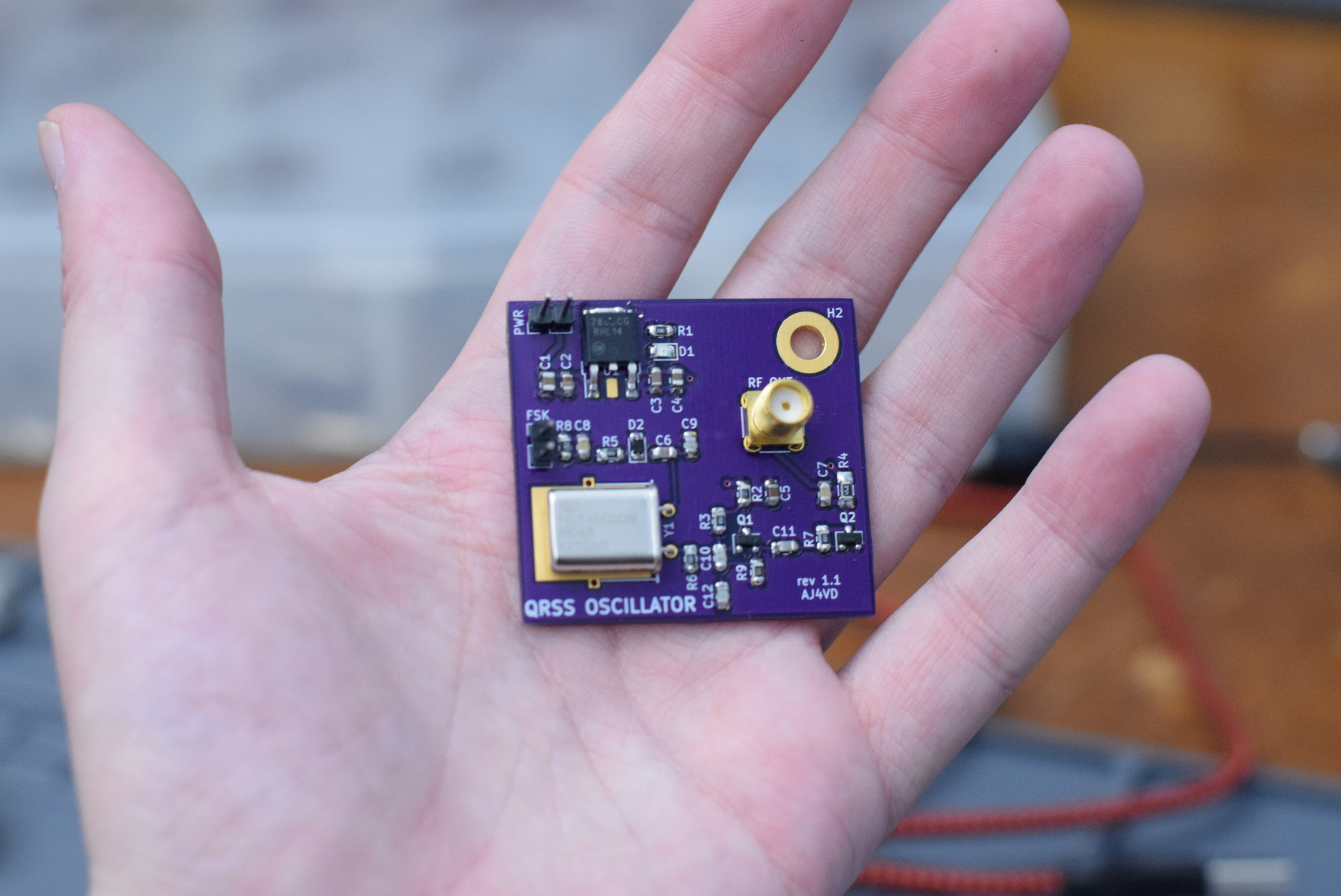
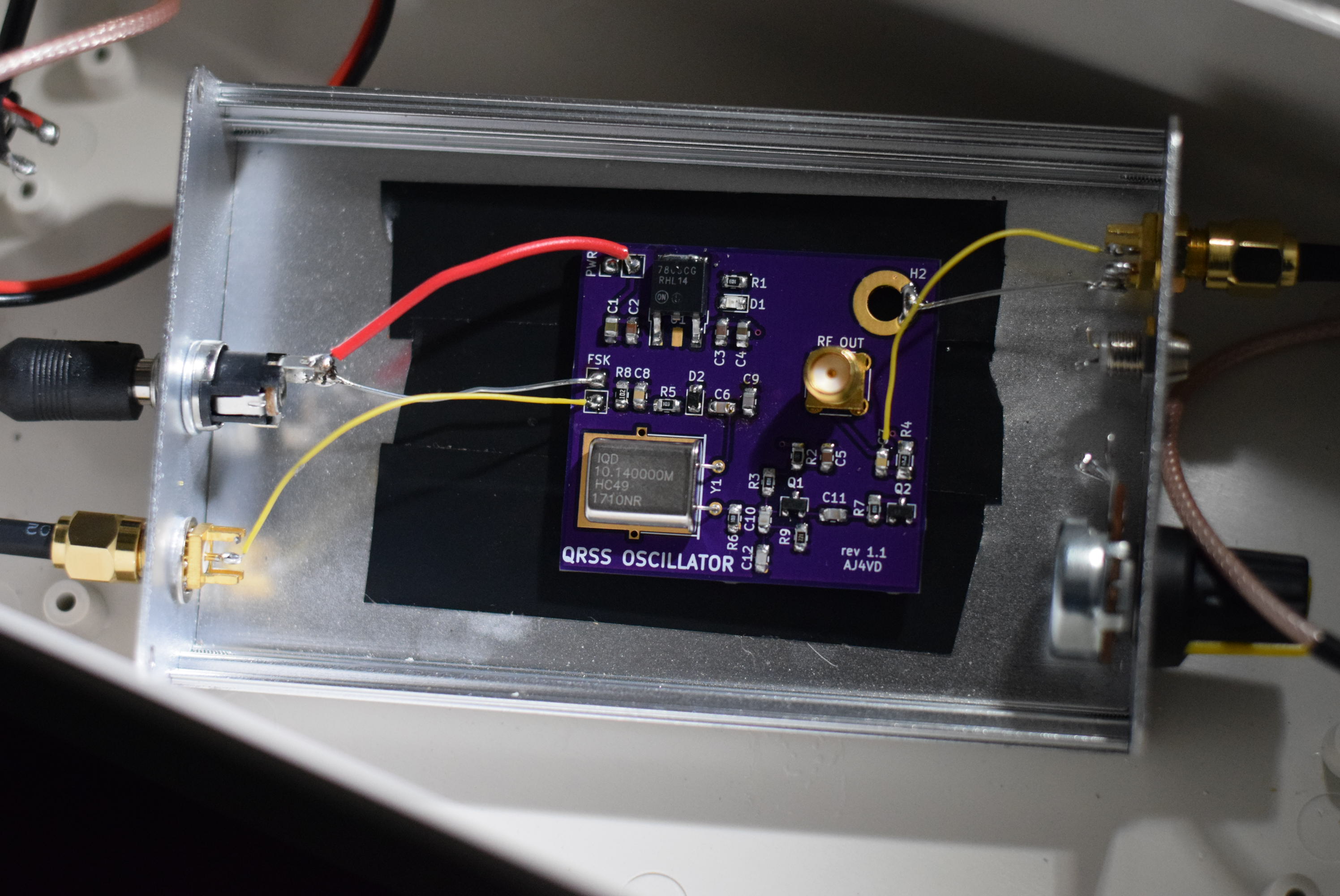
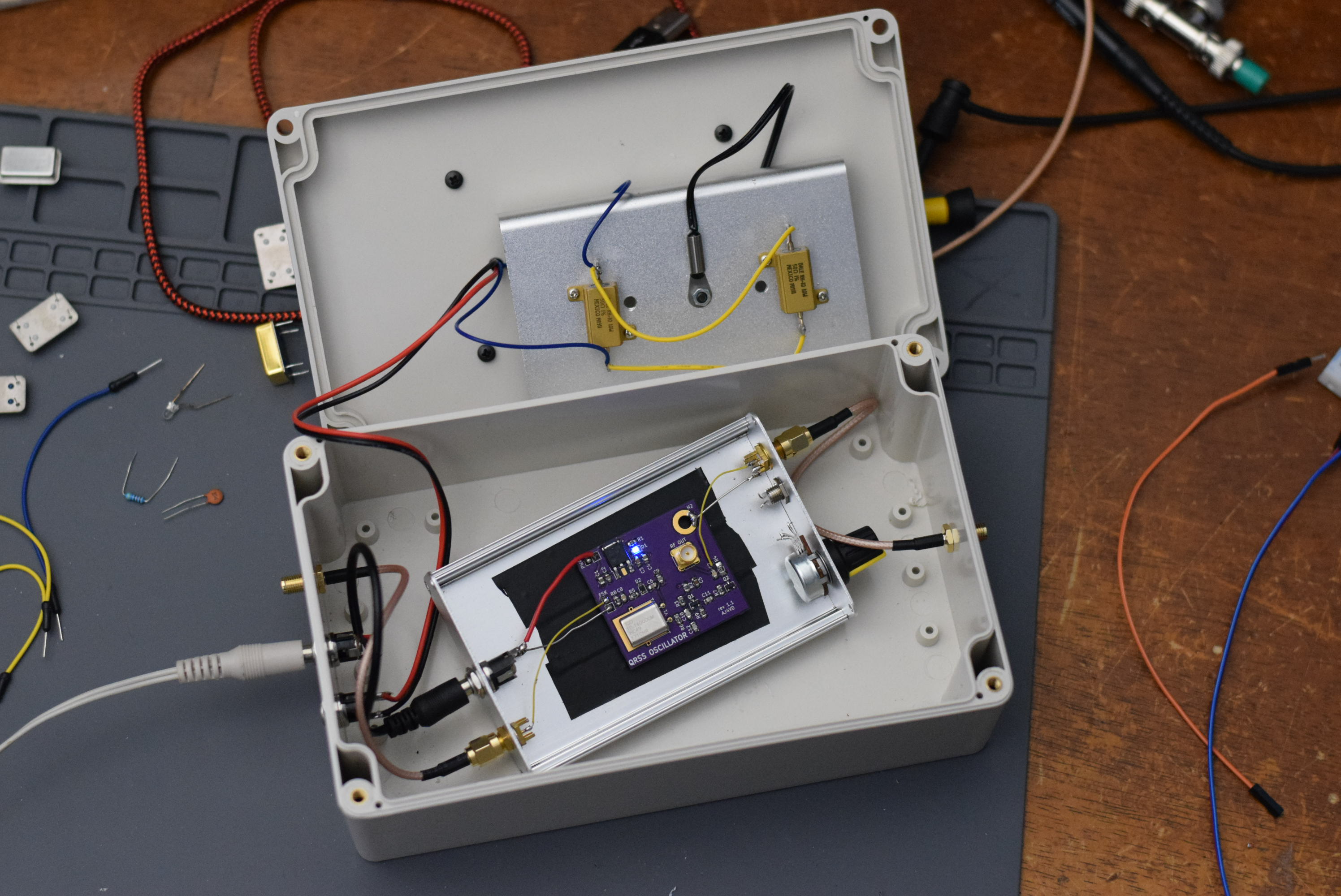
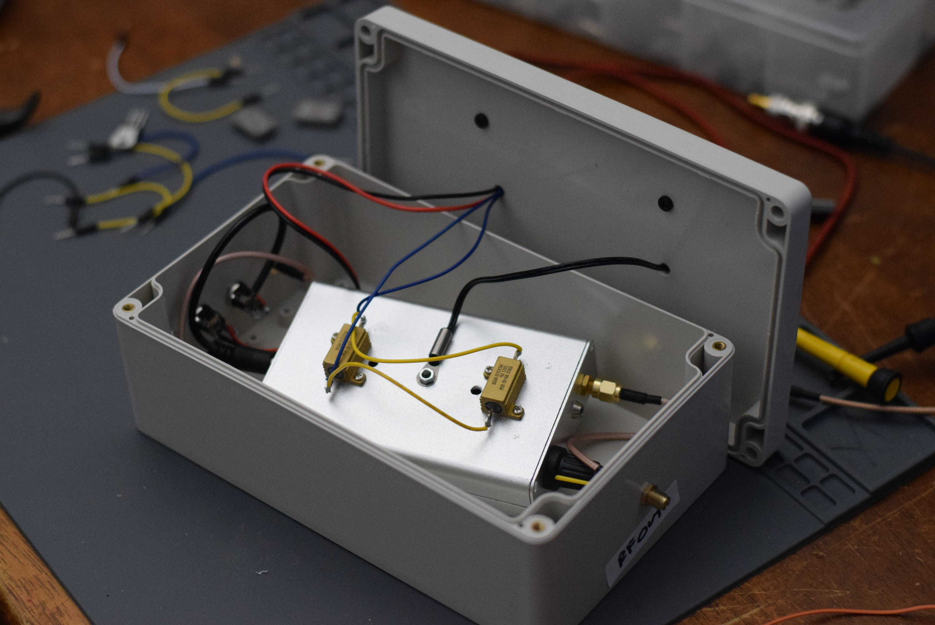
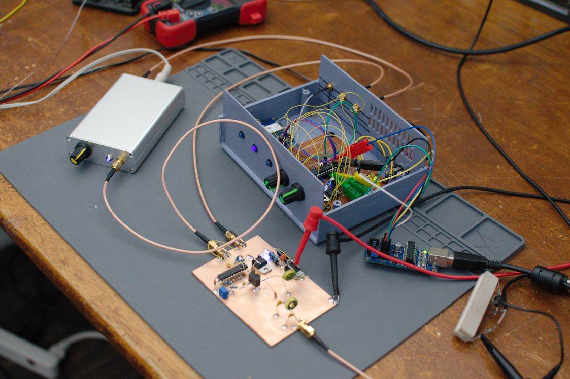
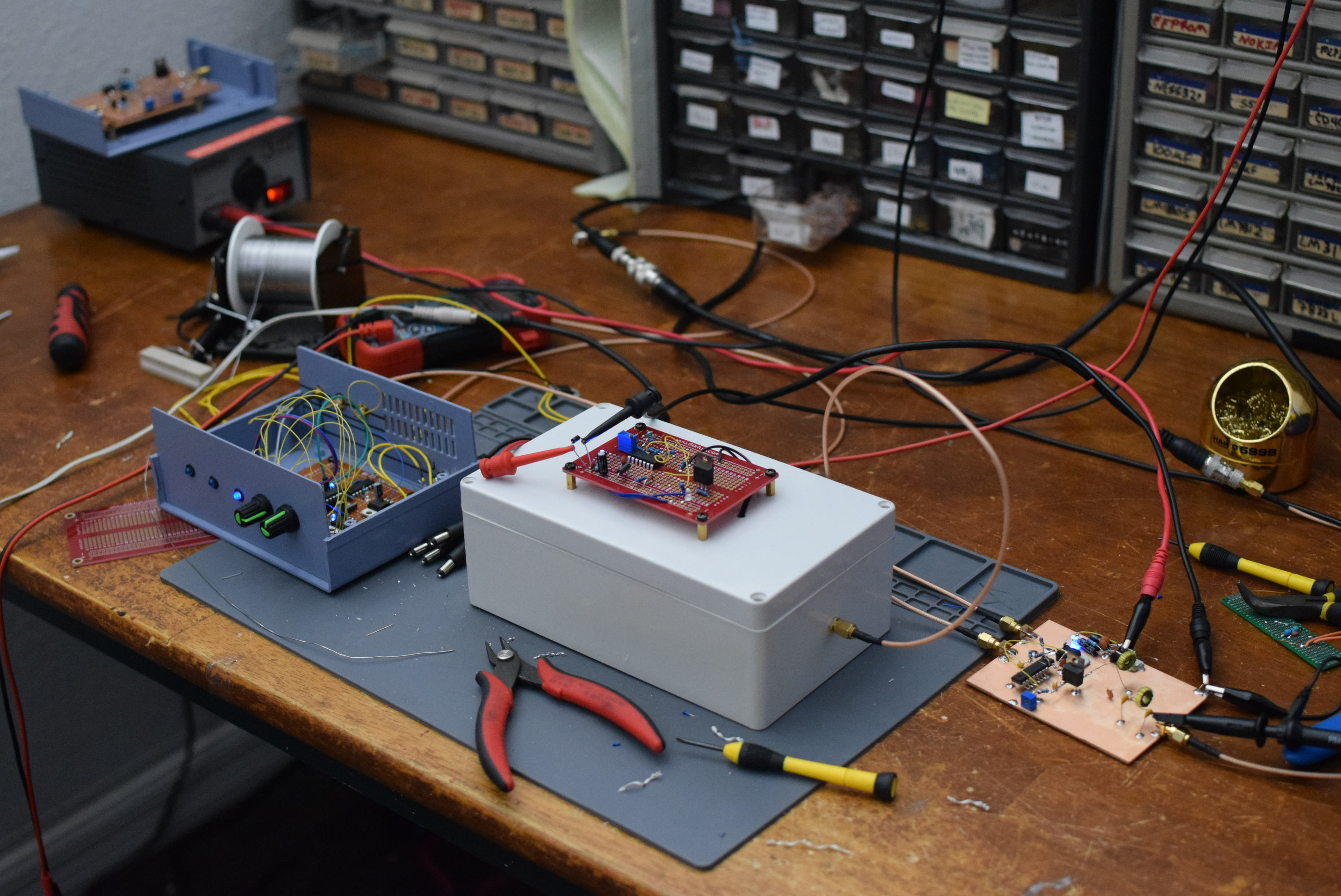
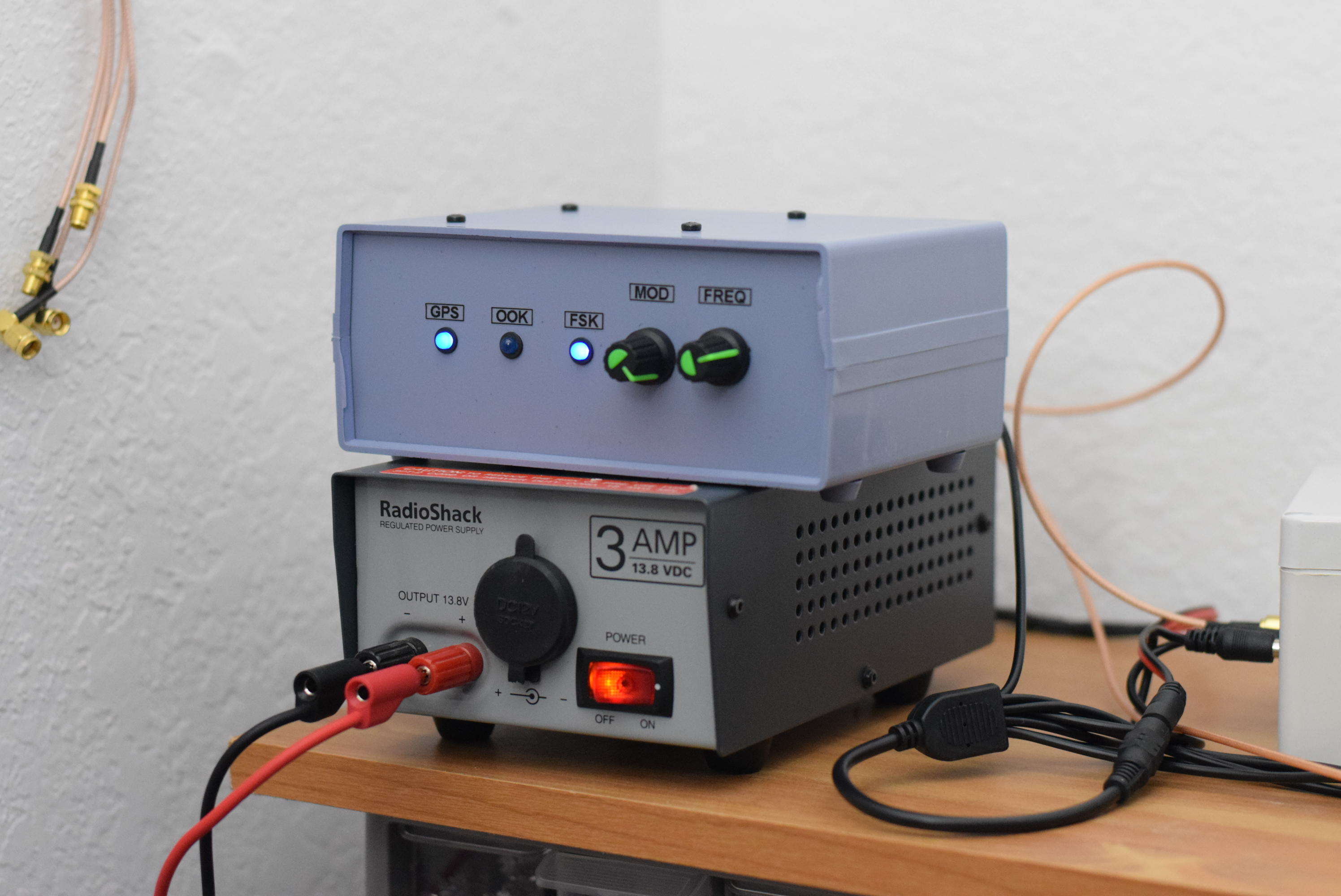
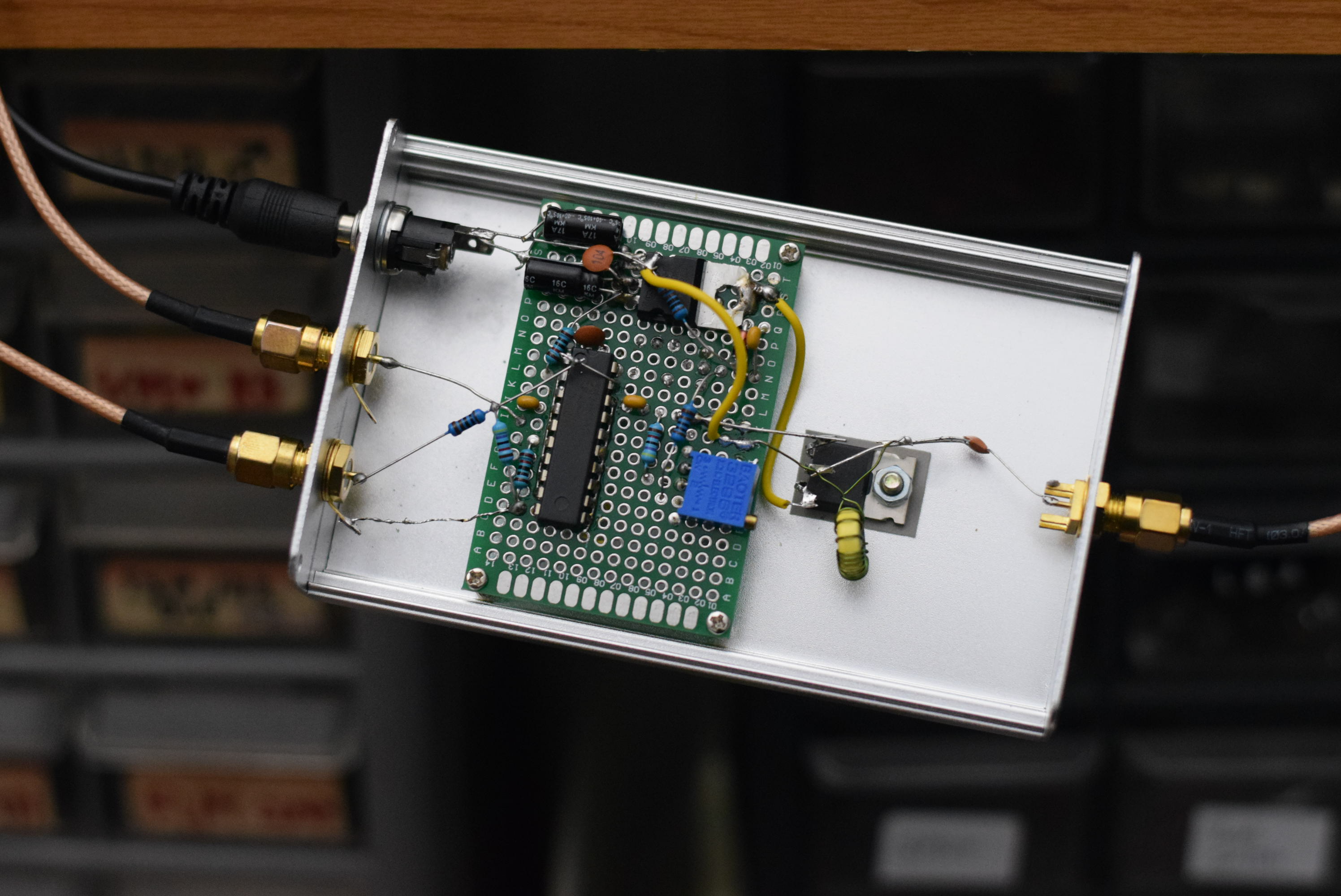
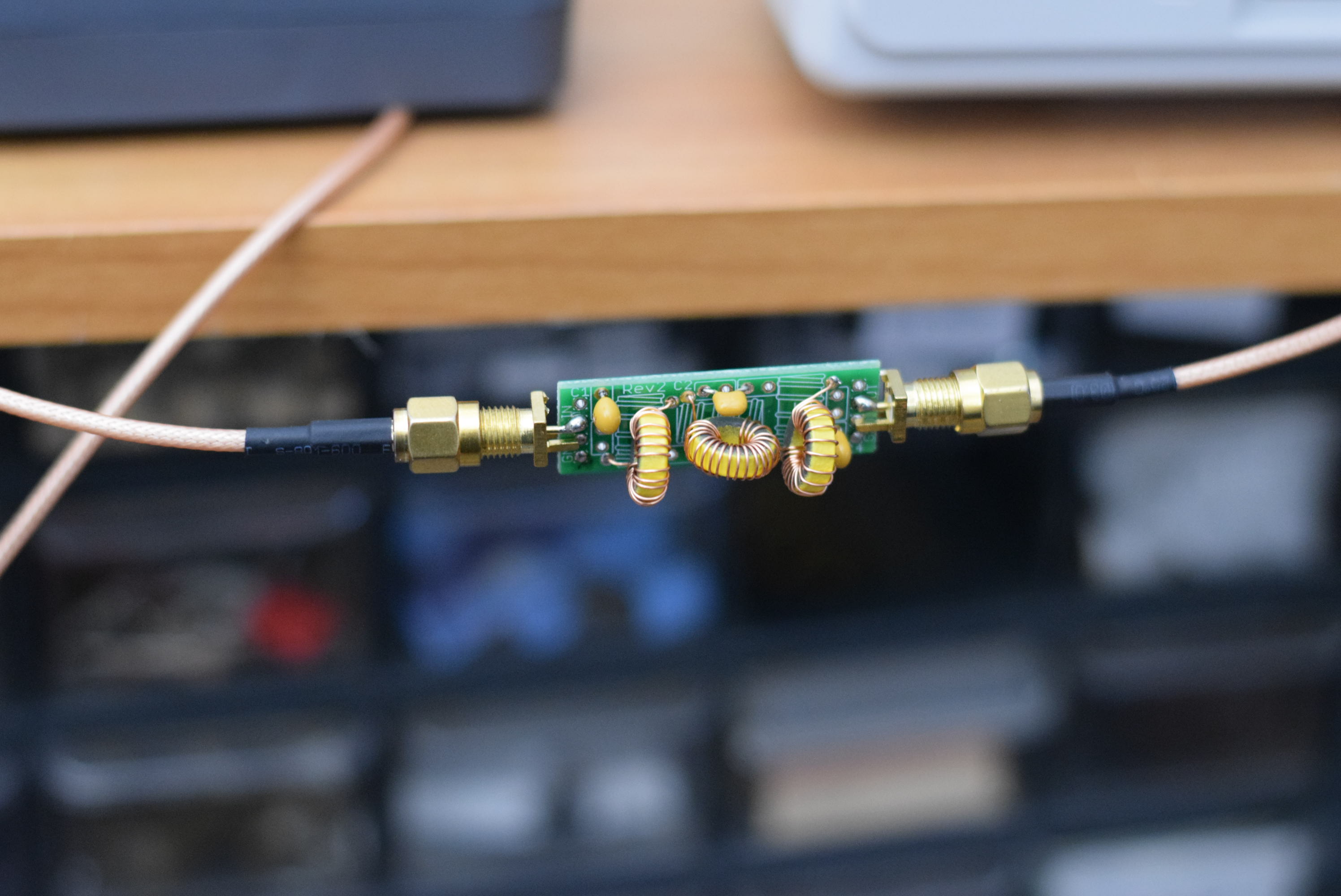
I experimented with QRSS on and off over the last decade, but all of my designs were pretty crude. Now that I have more experience, knowledge, and resources, I'd like to get back into the hobby.
There are a lot of crystal oven designs and chassis heater designs out there, and I'd like to get better at testing different designs. This requires precision temperature and frequency measurements and involves using a PC for data-logging and analysis. I'd like to get a better understanding of the temperature vs. frequency profile not just of crystals, but of the entire oscillator circuit. I'm interested in developing a SMT oscillator board with the temperature controller built-in (using SMT resistors to heat the PCB, temperature-stabilizing the entire oscillator rather than just the crystal).
I'd also like to improve QRSS Plus, and see about creating an open-source QRSS spectrograph like Argo now that I have experience developing Windows applications with C#. While my previous efforts (in Python) were interesting, I now have a strong appreciation for click-to-run software that works with minimal complexity.
| Qty | Value | Footprint | References |
|---|---|---|---|
| 6 | 10k | Resistor_SMD:R_0805_2012Metric_Pad1.15x1.40mm_HandSolder | R1, R3, R5, R6, R7, R14 |
| 4 | .1u | Capacitor_SMD:C_0805_2012Metric_Pad1.15x1.40mm_HandSolder | C2, C4, C5, C8 |
| 4 | 330 | Resistor_SMD:R_0805_2012Metric_Pad1.15x1.40mm_HandSolder | R10, R11, R12, R13 |
| 3 | 120p | Capacitor_SMD:C_0805_2012Metric_Pad1.15x1.40mm_HandSolder | C10, C11, C12 |
| 2 | 10u | Capacitor_SMD:C_0805_2012Metric_Pad1.15x1.40mm_HandSolder | C1, C3 |
| 2 | 1k | Resistor_SMD:R_0805_2012Metric_Pad1.15x1.40mm_HandSolder | R2, R8 |
| 2 | 33p | Capacitor_SMD:C_0805_2012Metric_Pad1.15x1.40mm_HandSolder | C6, C9 |
| 2 | MMBT3904 | Package_TO_SOT_SMD:SOT-23 | Q1, Q2 |
| 2 | MountingHole | MountingHole:MountingHole_4.3mm_M4_Pad_Via | H1, H2 |
| 1 | 10MHz | Crystal:Crystal_HC49-U_Horizontal_1EP_style2 | Y1 |
| 1 | 1n | Capacitor_SMD:C_0805_2012Metric_Pad1.15x1.40mm_HandSolder | C7 |
| 1 | 220 | Resistor_SMD:R_0805_2012Metric_Pad1.15x1.40mm_HandSolder | R9 |
| 1 | 50 | Resistor_SMD:R_1206_3216Metric_Pad1.42x1.75mm_HandSolder | R4 |
| 1 | BB132 | LED_SMD:LED_0805_2012Metric_Pad1.15x1.40mm_HandSolder | D2 |
| 1 | FSK | Connector_PinHeader_2.54mm:PinHeader_1x02_P2.54mm_Vertical | FSK |
| 1 | HEATING | LED_SMD:LED_0805_2012Metric_Pad1.15x1.40mm_HandSolder | HOT |
| 1 | L7805 | Package_TO_SOT_SMD:TO-252-3_TabPin2 | U1 |
| 1 | OVEN | Connector_PinHeader_2.54mm:PinHeader_1x04_P2.54mm_Vertical | OVEN |
| 1 | POWER | LED_SMD:LED_0805_2012Metric_Pad1.15x1.40mm_HandSolder | D1 |
| 1 | PWR | Connector_PinHeader_2.54mm:PinHeader_1x02_P2.54mm_Vertical | PWR |
| 1 | RF-OUT | Connector_Coaxial:SMA_Amphenol_132134-16_Vertical | J3 |
| 1 | Thermistor | Resistor_SMD:R_0805_2012Metric_Pad1.15x1.40mm_HandSolder | TH1 |
swharden/QRSS-hardware
A collection of resources related to QRSS hardware (TX and RX)

swharden/QRSS-hardware
A collection of resources related to QRSS hardware (TX and RX)


TechWave-Audio/TechWaveAudio-MidiControllerModule
TechWave Audio Midi Controller Module

keeos-io/ogham
Ogham — a dual-voice bytebeat synthesizer for Eurorack. Firmware (MIT) and hardware (CC BY-SA 4.0).

alorcs/Irrigation-System-v2
The external footprints used can be found in the Imports folder.

AudioMorphology/ParrotRev2
Parrot is a 12hp Eurorack digital delay powered by a Raspberry Pi Pico microcontroller.


Cherry-Blossom-Development/GreywireStudio
GreywireStudio - a combined software/hardware product
It measures 42 × 42 mm and has 2 copper layers, 1.6 mm thick.
40 parts, built around the L7805 and MMBT3904. The full list of its parts is on this page, with links to each part's symbol and footprint where PCBKit's library has them.
From the swharden/QRSS-hardware repository on GitHub, at the commit this page was made from: the board is builds/oscillator/rev1.2/fsk oscillator.kicad_pcb. PCBKit opens the board in the browser, with nothing to install.
Its repository states no licence, so its author keeps all rights: ask swharden before reusing the design.