Skip to the content
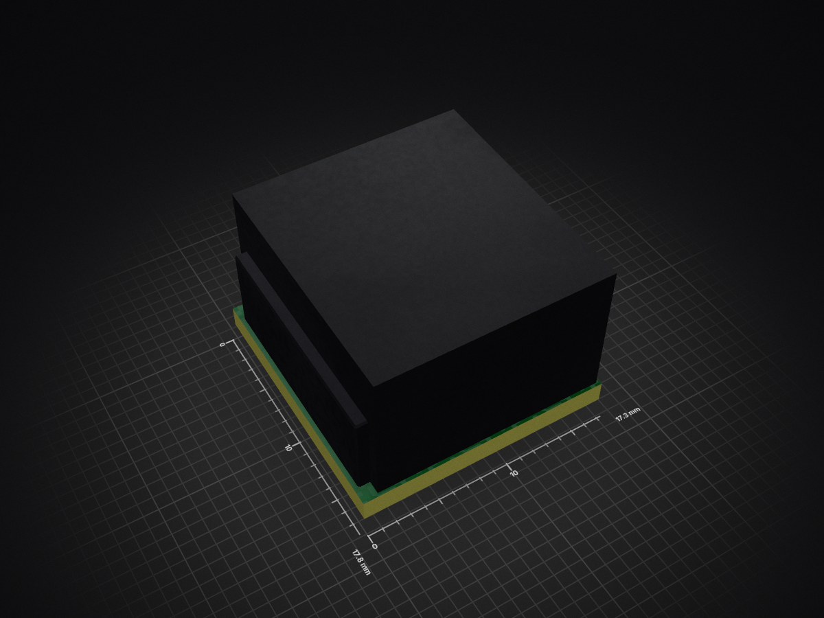
2 layers17.3 × 17.8 mmRotaryEncoderCarrierBoard, the printed circuit board in 3D

TechWave Audio Midi Controller Module

Size
17.3 × 17.8 mm
Copper layers
2
Thickness
1.6 mm
Parts
2
Nets
5
Pads
13
Tracks, vias
11, 0
Routed
Yes
KiCad
KiCad 10.0 (file 20260206)
Created
18 Jun 2026
Updated
7 Sep 2026

Overview

RotaryEncoderCarrierBoard is an open-source printed circuit board by TechWave-Audio, from the TechWave-Audio/TechWaveAudio-MidiControllerModule repository on GitHub, published under the BSD-3-Clause licence. It is a 2-layer board of 17.3 × 17.8 mm with 2 parts on 5 nets, routed with 11 tracks and 0 vias.

It belongs with the audio and music boards of this library.

README

README.md

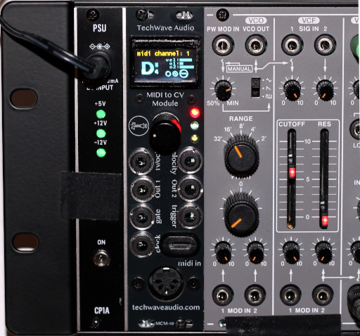
TechWave Audio MIDI to CV Module : MCM-100

A monophonic MIDI controller Eurorack module using the Raspberry Pi Pico (RP2040).

Brought to you by TechWave Audio

TechWave Audio Midi Controller Module

Features

  • Single or omni MIDI channel input
  • MIDI input via class-compliant USB-C or standard 5-pin MIDI cable
  • Four CV outputs for note (1v/oct), Velocity, assignable Out 1 and Out 2
    • 1v/octave through 10 octaves (at 0 to +10v), or 5 octaves (at 0 to +5v)
    • Two CV outputs with flexible routing
    • All CV outputs voltage selectable from 0v to +10v or 0 to +5v
  • Expandable with additional four flexible-routed CV outputs.
  • Gate, trigger, and clock full 0 to +5v outputs with divisible clock sync ticks
  • Selectable note priority (last, highest, lowest)
  • Tuneable pitch and velocity adjust
  • Customizable trigger output duration pulse width
  • Pitch bend response range from 0 to 5 octaves
  • Real time display of note and output states
  • Settings persist to on-board flash ROM
  • 6hp wide, 3U height
  • Max Power Draw:
    • +12v: 72mA (80mA with expansion)
    • -12v: 15mA (20mA with expansion)
    • +5v: 0mA

Help support our work!


Responds to the following MIDI messages:

  • Note on / off: sends/stops the note and velocity outputs.
    • Sends a trigger pulse on note on, and turns on the gate for the duration of the note.
    • For +10v output, responds to C-1 (note number 0) to B9 (note number 119).
    • For +5v output, responds to C2 (middle-C, note number 36) to B6 (note number 95).
  • Volume: increases or decreases the velocity output.
  • Pitch bend: modifies any currently playing note. Adjustable range from 0 to 5 octaves.
  • Sustain: holds a note on while the sustain is active.
  • Aftertouch: selectable as an aux and/or control output.
  • Expression: selectable as an aux and/or control output.
  • Mod wheel: selectable as an aux and/or control output.
  • Effect 1: selectable as an aux and/or control output.
  • Effect 2: selectable as an aux and/or control output.
  • Start and Continue sequence: selectable as an aux and/or control output.
  • Stop sequence: selectable as an aux and/or control output.
  • Mute (all notes off): clears any note, velocity, and gate outputs.
  • Clock tick: MIDI clock ticks are sent directly to the Clock output and can be routed as an aux and/or control output.
  • Reset: reset the MIDI input messaging queue and stops any output.

Inputs

  • MIDI in: single channel or respond to all channels (omni)
    • Both MIDI via UART and class-compliant USB MIDI
  • Menu navigation: Rotary encoder with push switch

Outputs

  • Four CV outputs:
    • Note: 0 to 10v output (selectable to 0 to 5v) for CV with 1v per octave.
    • Velocity: 0 to 10v output (selectable to 0 to 5v) for velocity / volume
    • Out 1: customizable CV output (0v to +10v max, selectable to 0v to +5v)
    • Out 2: customizable CV output (0v to +10v max, selectable to 0v to +5v)
  • Trigger: single pulse when a note turns on, with customizable pulse on time (high / low level output)
  • Gate: signal goes high while a note is on (high / low level output)
  • Clock: 1ms pulse with each MIDI clock tick (high / low level output). Selectable to various clock divisions.

Using the MCM-100-EX Expansion Module, you can also add an additional four assignable CV outputs.


Power

This module requires a 10 pin (2x05 IDC connector) Eurorack power connection.

Be certain when you plug the connector in that the orientation is the correct way, with the -12v line (usually with the red stripe) on the left when looking at the rear of the module.


Usage

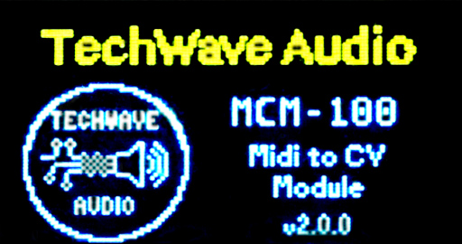
On startup, you should see the boot screen with the current version:

starting boot screen

The note and clock LEDs should turn on and off a few times before the dashboard screen is shown and the module is ready to be used.

The user manual can be found on the TechWave Audio website.

Dashboard

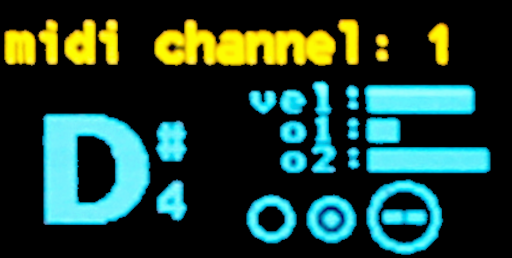
main dashboard display

The dashboard shows the status of the current MIDI channel that it is listening on, as well as various outputs:

  • The note and octave
  • vel: The current velocity (corresponding to 0v to +10/+5v)
  • o1: The current Out 1 value (corresponding to 0v to +10/+5v)
  • o2: The current Out 2 value (corresponding to 0v to +10/+5v)
  • Indicators for the state of the trigger, gate, and clock
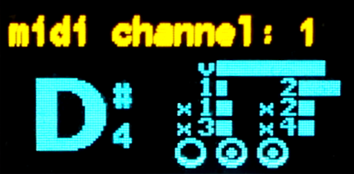
dashboard with expansion

If the MCM-100-EX expansion module is attached, additionally it will show:

  • x1: The current Out X1 value (corresponding to 0v to +10/+5v)
  • x2: The current Out X2 value (corresponding to 0v to +10/+5v)
  • x3: The current Out X3 value (corresponding to 0v to +10/+5v)
  • x4: The current Out X4 value (corresponding to 0v to +10/+5v)

While using the module, you can turn the dashboard display on and off via the display settings menu. You can also adjust how often the display refreshes (set to a longer time if display events start to get dropped, shorter time for more frequent updates).

Settings Menu

There are numerous settings available from the settings menu. Pressing the encoder button on the dashboard display (regardless if the display is visible or not) will enter the menu. See the Menu System documentation for the menu system details.

Note: any settings are not persisted until you exit the menu back to the dashboard (with the exception of when resetting the settings to default).

Building the Firmware From Source

Prerequisites

  • Raspberry Pi Pico SDK
  • CMake
  • Your favourite C++ compiler
  • A compatible toolchain for building Pico firmware

Setup

  1. Initialize the Git submodules:
    1. run: git submodule init
    2. run: git submodule update
  2. Copy the .env.cmake.sample to .env.cmake
  3. Edit your .env.cmake for the following variables:
text
PICO_SDK_PATH {the path to the PICO_SDK directory)
PICO_TOOLCHAIN_PATH (path to the pico toolchain for your build machine)

# You should _not_ have to change the following
set(PICO_PLATFORM rp2040)
set(PICO_BOARD pico)

Build script

text
./build.sh

This will run the full clean and build.

The firmware file will be put in:

text
./dist/TechWaveAudio-MCM-v2.0.0.uf2

Firmware Updates

For this, you'll need a firmware release (or build your on locally), as well as a USB cable that has a micro-usb port on one end.

  1. Power off your rack.
  2. Remove the module from your rack but keep the module plugged in via the power cable.
  3. Download the desired firmware file version from the GitHub repository firmware release. You only need to download the file with the .uf2 extension.
  4. Plug your USB-C cable into the jack on the front of the module and the other end into the computer with the firmware.
  5. While holding down the small boot select (BOOTSEL) button on the board, power on the module. Keep holding the boot select button until the module appears on your computer. The on-board Raspberry Pi Pico board will appear as a mass storage device, usually named “RPI-RP2”
  6. Copy the downloaded firmware .uf2 file to the storage device. When complete, the module should reboot.
  7. Power off your rack again.
  8. Disconnect your USB cable from the module and your computer. Your computer may give you a warning about the device not being properly ejected. You can safely ignore this warning.
  9. Put the module back into your rack and power back on.

Note that any settings you many have modified will be reset to any default.

Design

Schematic, PCB, and hardware

See the hardware design documentation for information on the schematic and PCB design for the module.

Note - all files provided including KiCad designs and any gerber files are provided as-is and to be used at your own risk. TechWave Audio does not guarantee the accuracy or any correctness of these files. See the HW_LICENSE license file for more, specifically the section "6 DISCLAIMER AND LIABILITY".

Licensing

Software in this repository is licensed under the BSD-3 License. By using or contributing content to this repository you are agreeing to place your contributions under this license.

Hardware designs for this repository are licensed under the CERN-OHL-S (CERN Open Hardware License).

Parts of this repository may reference, depend on, or use compiled third party libraries. See NOTICE.txt for additional details.

Parts

2
QtyValueFootprintReferences
1RotaryEncoder_SwitchRotary_Encoder:Rotary_Encoder_Bourns_PEC11H-4225F-S0024SW1
1~Rotary_Encoder:Rotary_Encoder-PEC11-Breakout_BoardSW2

More from TechWave-Audio/TechWaveAudio-MidiControllerModule

3
  • 2 layers30 × 90 mmTechWaveAudio MCM-100-Main, the printed circuit board in 3D

    TechWaveAudio MCM-100-Main

    TechWave-Audio/TechWaveAudio-MidiControllerModule

    TechWave Audio Midi Controller Module

    50 parts4BSD-3-Clause
  • 2 layers30 × 90 mmTechWaveAudio MidiController, the printed circuit board in 3D

    TechWaveAudio MidiController

    TechWave-Audio/TechWaveAudio-MidiControllerModule

    TechWave Audio Midi Controller Module

    41 parts4BSD-3-Clause
  • 2 layers10 × 110 mmTechWaveAudio MCM-100-EX, the printed circuit board in 3D

    TechWaveAudio MCM-100-EX

    TechWave-Audio/TechWaveAudio-MidiControllerModule

    TechWave Audio Midi Controller Module

    21 parts4BSD-3-Clause

Similar boards

  • 2 layers37 × 19 mmPassive rpi hub75-adapter, the printed circuit board in 3D

    Passive rpi hub75-adapter

    hzeller/rpi-rgb-led-matrix

    Controlling up to three chains of 64x64, 32x32, 16x32 or similar RGB LED displays using Raspberry Pi GPIO

    2 parts4.4kGPL-2.0
  • 2 layersDiode template, the printed circuit board in 3D

    Diode template

    adamws/kicad-kbplacer

    KiCad plugin for automatic keyboard's key placement and routing

    2 parts547GPL-3.0
  • 2 layers20.3 × 15.2 mmL0 button, the printed circuit board in 3D

    L0 button

    Luos-io/luos_engine

    Open-source and real-time orchestrator for cyber-physical-systems, to easily design, test and deploy embedded applications and digital twins.

    2 parts546MIT
  • 2 layers35.1 × 46.8 mmSDEX2M2 Breakout Board, the printed circuit board in 3D

    SDEX2M2 Breakout Board

    NVNTLabs/switch2-SDEX2M2

    Micro SD Express to M.2 NVME Adapter for Nintendo Switch 2

    2 parts542GPL-3.0
  • 2 layers59.3 × 36.6 mmExpansionBoardTemplate, the printed circuit board in 3D

    ExpansionBoardTemplate

    BlueSCSI/BlueSCSI-v2

    BlueSCSI v2/Ultra - an open source, open hardware, SCSI emulator using the Pi Pico PR2040 and Pico 2 RP2350

    2 parts459GPL-3.0
  • 2 layersAlpha.9mm.wire, the printed circuit board in 3D

    Alpha.9mm.wire

    ohmtech-rdi/eurorack-blocks

    Software to Hardware Prototyping for Eurorack using C++, Max/Gen~ or Faust

    2 parts410
  • 2 layers26.7 × 64 mmGpu power, the printed circuit board in 3D

    Gpu power

    dennisss/dacha

    Monorepo for awesome tools/projects/libraries

    2 parts397Apache-2.0

Questions

How big is the RotaryEncoderCarrierBoard PCB?

It measures 17.3 × 17.8 mm and has 2 copper layers, 1.6 mm thick.

What parts does the RotaryEncoderCarrierBoard use?

2 parts. The full list of its parts is on this page, with links to each part's symbol and footprint where PCBKit's library has them.

Where can I download the RotaryEncoderCarrierBoard KiCad files?

From the TechWave-Audio/TechWaveAudio-MidiControllerModule repository on GitHub, at the commit this page was made from: the board is design/RotaryEncoderCarrierBoard/RotaryEncoderCarrierBoard.kicad_pcb and its schematic design/RotaryEncoderCarrierBoard/RotaryEncoderCarrierBoard.kicad_sch. PCBKit opens the board in the browser, with nothing to install.

Can I use the RotaryEncoderCarrierBoard design in my own project?

Its repository publishes it under the BSD-3-Clause licence: you may reuse it on that licence's terms (keep the author's notice, and for a copyleft licence share your changes alike).