4 layers54.3 × 75 mm
Hardwareddc aux breakout
TeaRex-coder/hardwareddc
a custom PCB that makes adjusting monitor settings easy and convenient
19 parts34BSD-3-Clause
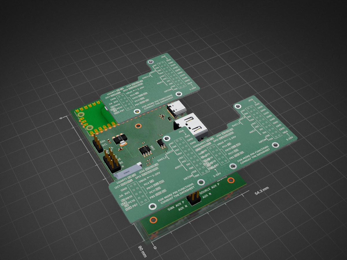
 TeaRex-coder/hardwareddc34
a custom PCB that makes adjusting monitor settings easy and convenient
Hardwareddc aux mitm is an open-source printed circuit board by TeaRex-coder, from the TeaRex-coder/hardwareddc repository on GitHub, published under the BSD-3-Clause licence. It is a 4-layer board of 54.3 × 90 mm with 48 parts on 89 nets, routed with 514 tracks and 122 vias.
It is built around the SN65MLVD200AD and AMS1117-3.3. Its parts include 22 resistors, 11 capacitors, 7 connectors, 3 ICs and 1 diode. It belongs with the RP2040 boards of this library.


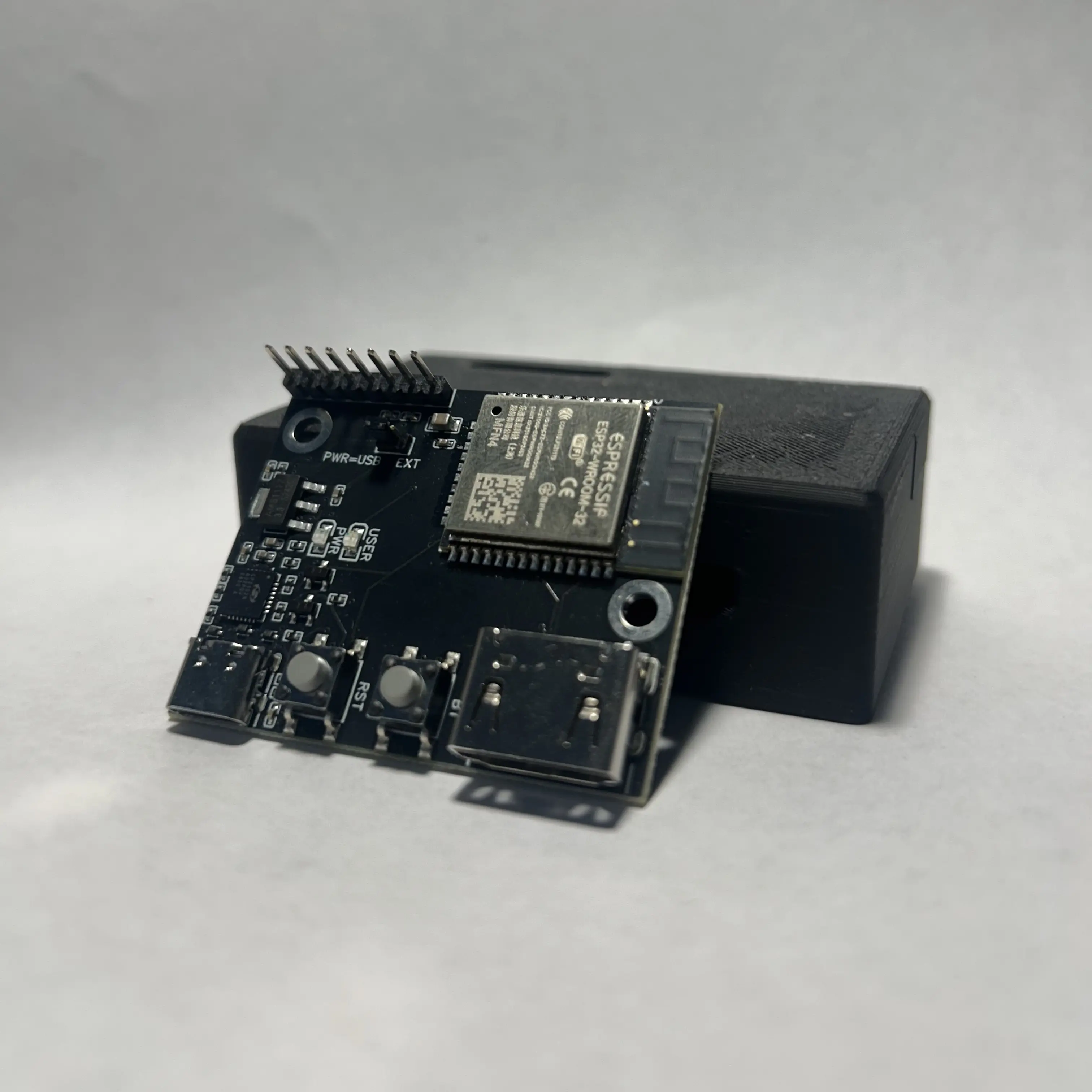
DDC/CI (Display Data Channel Command Interface) lets you control monitors with software instead of navigating the nipple or rear buttons. In a perfect world, we could control all monitors with DDC, but unfortunately, that's not the case...
If you're in one of those last three situations HardwareDDC might be for you! It uses an ESP32 to send raw I2C DDC signals to your monitor's HDMI port while another port is used for video.
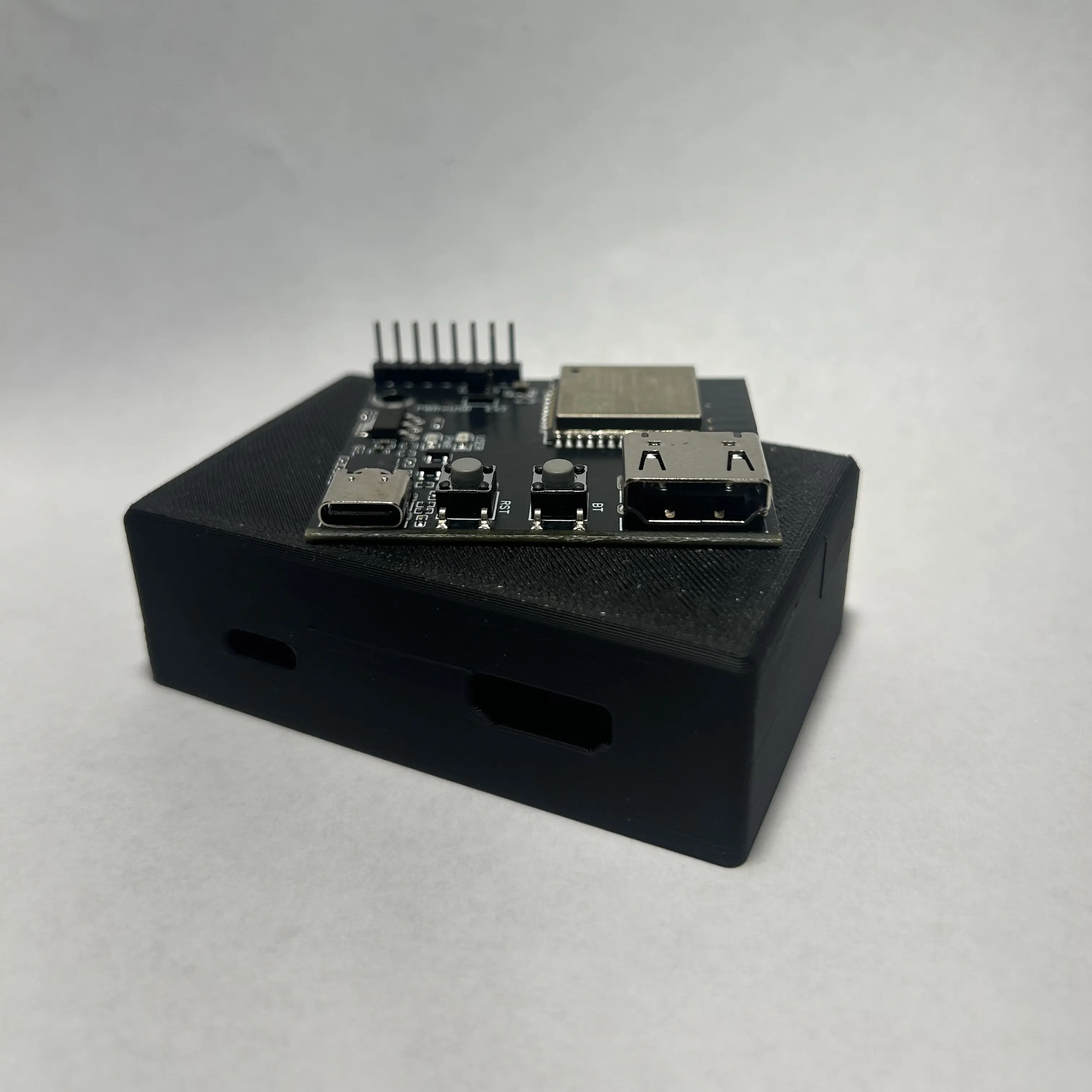
HardwareDDC features an ESP32 with reset and boot buttons, an HDMI connector exposing GND, SDA and SCL, and it's powered by USB-C which also exposes the UART console. Optionally, it can be powered by 5V directly through the GPIO pins, and additional GPIO pins are available for debugging and future expandability.
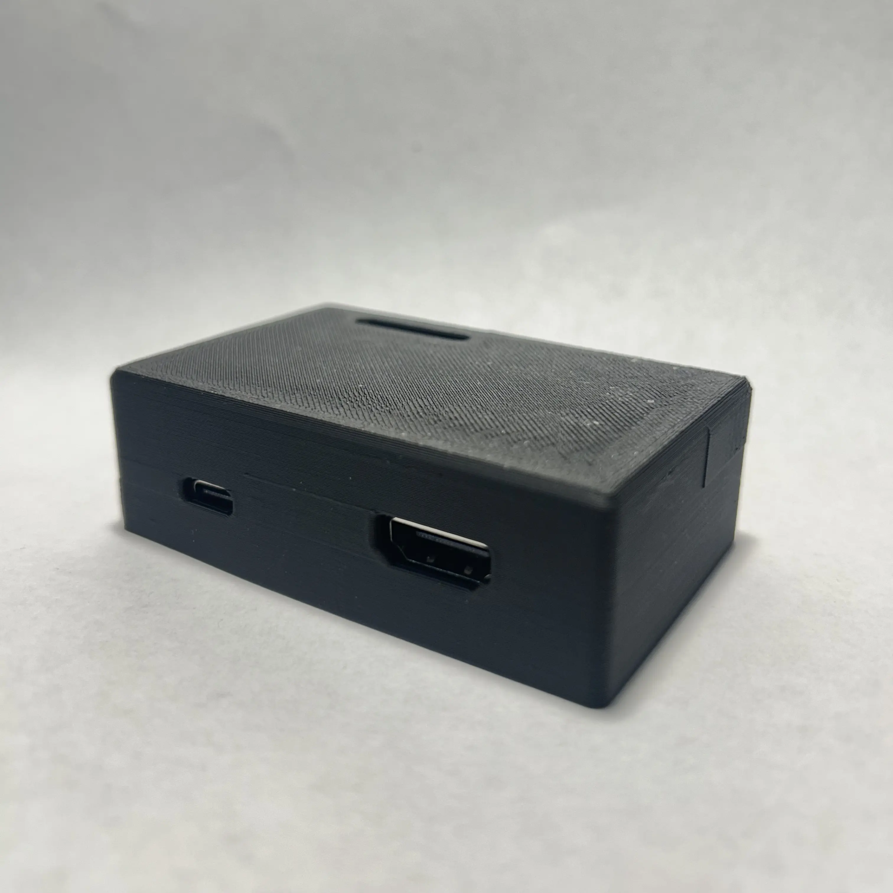
The PCB and the 3D printed ABS case are available on the website, and the files can be found here.
Once you have your board, you can flash the firmware with the web installer.
Controlling HardwareDDC is done through hotkeys, instructions can be found here

Thank you PCBWay for sponsoring this project providing PCB prototyping <3
TL;DR Would I recommend PCBWay's PCB service? Yes!
It's impossible for me to provide an unbiased opinion as PCBWay has provided boards free of charge to help me work on this project. However, my experience was overall positive. Starting with their marketing rep Liam, he offered a partnership respectfully and fairly. When placing the order, the team helped me, a novice to PCB design and PCBWay's services, follow some best practices regarding board design and ordering. Finally, the production tracker helped keep my curious mind informed and the assembled product functioned as intended.
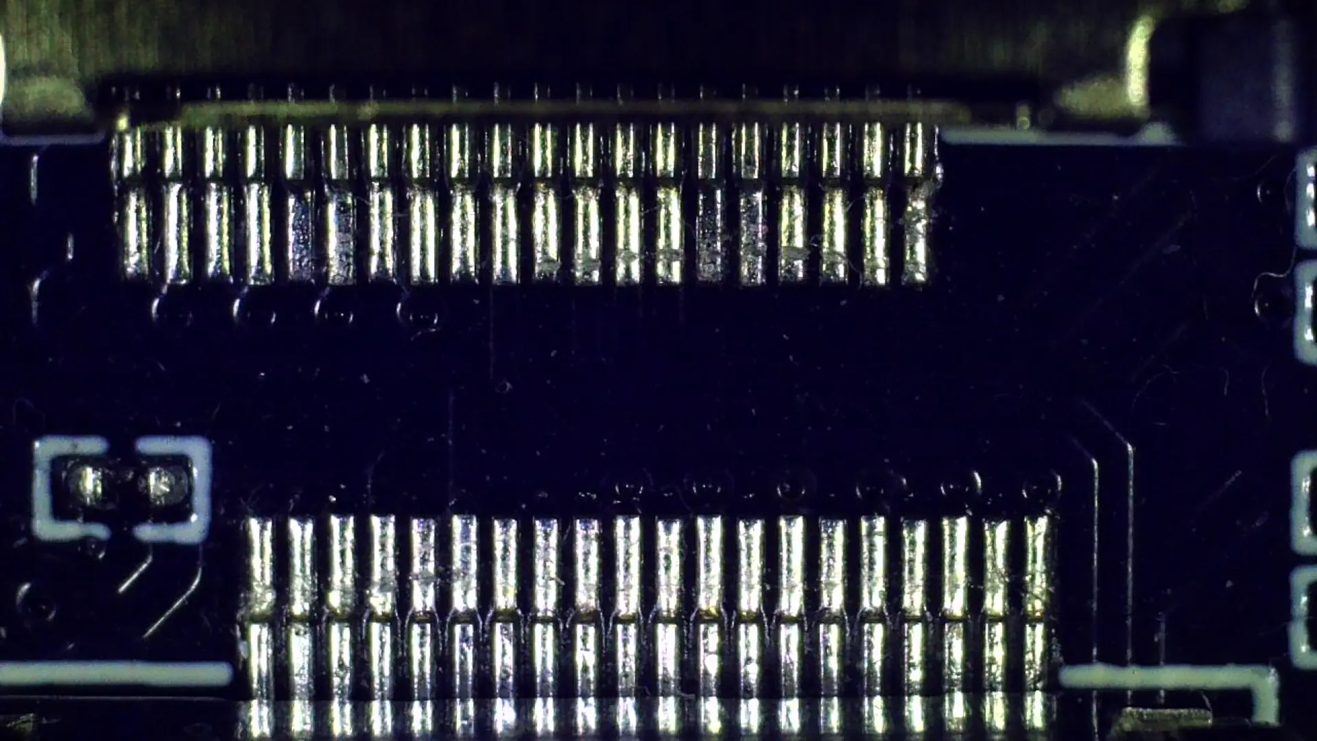
When researching PCBWay's brand before agreeing to a partnership, I noticed a customer expressing disappointment in the assembly of an HDMI connector. I took this with a grain of salt, as the dissatisfied customers are generally the loudest, but it was still a concern. The boards I received had well-soldered DisplayPort connector pins to a level as good, if not better than I could do by hand.
I hope the experience I received is representative of any regular PCBWay customer despite PCBWay expecting a review. If you need PCB prototyping for your project, consider giving them a go :)

Thank you Flux AI for providing breakout boards for HardwareDDC <3
Shoutout to these projects that make HardwareDDC possible:
| Qty | Value | Footprint | References |
|---|---|---|---|
| 6 | 0 | Resistor_SMD:R_0603_1608Metric | R15, R16, R17, R18, R19, R20 |
| 6 | 100n | Capacitor_SMD:C_0402_1005Metric | C1, C3, C4, C5, C8, C9 |
| 4 | 51 | Resistor_SMD:R_0402_1005Metric | R4, R5, R11, R12 |
| 3 | MountingHole_Pad_MP | MountingHole:MountingHole_2.2mm_M2_ISO7380_Pad | H1, H2, H3 |
| 2 | 100K | Resistor_SMD:R_0402_1005Metric | R6, R7 |
| 2 | 10k | Resistor_SMD:R_0402_1005Metric | R1, R8 |
| 2 | 10uF | Capacitor_SMD:C_0603_1608Metric | C7, C10 |
| 2 | 1K5 | Resistor_SMD:R_0402_1005Metric | R3, R10 |
| 2 | 1M | Resistor_SMD:R_0402_1005Metric | R13, R14 |
| 2 | 1n | Capacitor_SMD:C_0402_1005Metric | C2, C6 |
| 2 | 3K3 | Resistor_SMD:R_0402_1005Metric | R2, R9 |
| 2 | 47272-0001 | 47272-0001:CONN_47272-0001_MOL | J1, J4 |
| 2 | 5K1 | Resistor_SMD:R_0402_1005Metric | R21, R22 |
| 2 | SN65MLVD200AD | Package_SO:SOIC-8_3.9x4.9mm_P1.27mm | U1, U2 |
| 1 | 100nF | Capacitor_SMD:C_0603_1608Metric | C11 |
| 1 | AMS1117-3.3 | Package_TO_SOT_SMD:SOT-223-3_TabPin2 | U3 |
| 1 | Conn_01x03_Pin | Connector_PinHeader_2.54mm:PinHeader_1x03_P2.54mm_Vertical | J9 |
| 1 | Conn_02x02_Odd_Even | Connector_PinHeader_2.54mm:PinHeader_2x02_P2.54mm_Vertical | J7 |
| 1 | Conn_02x04_Odd_Even | Connector_PinHeader_2.54mm:PinHeader_2x04_P2.54mm_Vertical | J8 |
| 1 | D_TVS | Diode_SMD:D_SOD-323 | D1 |
| 1 | HDMI_A | Connector_Video:HDMI_A_Molex_208658-1001_Horizontal | J5 |
| 1 | RaspberryPi_Pico | Module:RaspberryPi_Pico_SMD | A1 |
| 1 | USB_C_Receptacle_USB2.0_16P | Connector_USB:USB_C_Receptacle_GCT_USB4105-xx-A_16P_TopMnt_Horizontal | J6 |
TeaRex-coder/hardwareddc
a custom PCB that makes adjusting monitor settings easy and convenient


pascallanger/DIY-Multiprotocol-TX-Module
Multiprotocol TX Module (or MULTI-Module) is a 2.4GHz transmitter module which controls many different receivers and models.

fossasia/pslab-hardware
PSLab Hardware Design and Schematics https://pslab.io


MaltWhiskey/Mega-Cube
16x16x16 PL9823 Cube with Teensy 4.0 and FlexIO driver

It measures 54.3 × 90 mm and has 4 copper layers, 0.54 mm thick.
48 parts, built around the SN65MLVD200AD and AMS1117-3.3. The full list of its parts is on this page, with links to each part's symbol and footprint where PCBKit's library has them.
From the TeaRex-coder/hardwareddc repository on GitHub, at the commit this page was made from: the board is experiments/hardwareddc-aux-mitm/hardwareddc-aux-mitm.kicad_pcb and its schematic experiments/hardwareddc-aux-breakout/hardwareddc-aux-breakout.kicad_sch. PCBKit opens the board in the browser, with nothing to install.
Its repository publishes it under the BSD-3-Clause licence: you may reuse it on that licence's terms (keep the author's notice, and for a copyleft licence share your changes alike).