4 layers50 × 50 mm
STM32 DEV BOARD
MatheusCipolotti/STM32_Codes
Repository dedicated to storing programming on STM32
51 parts
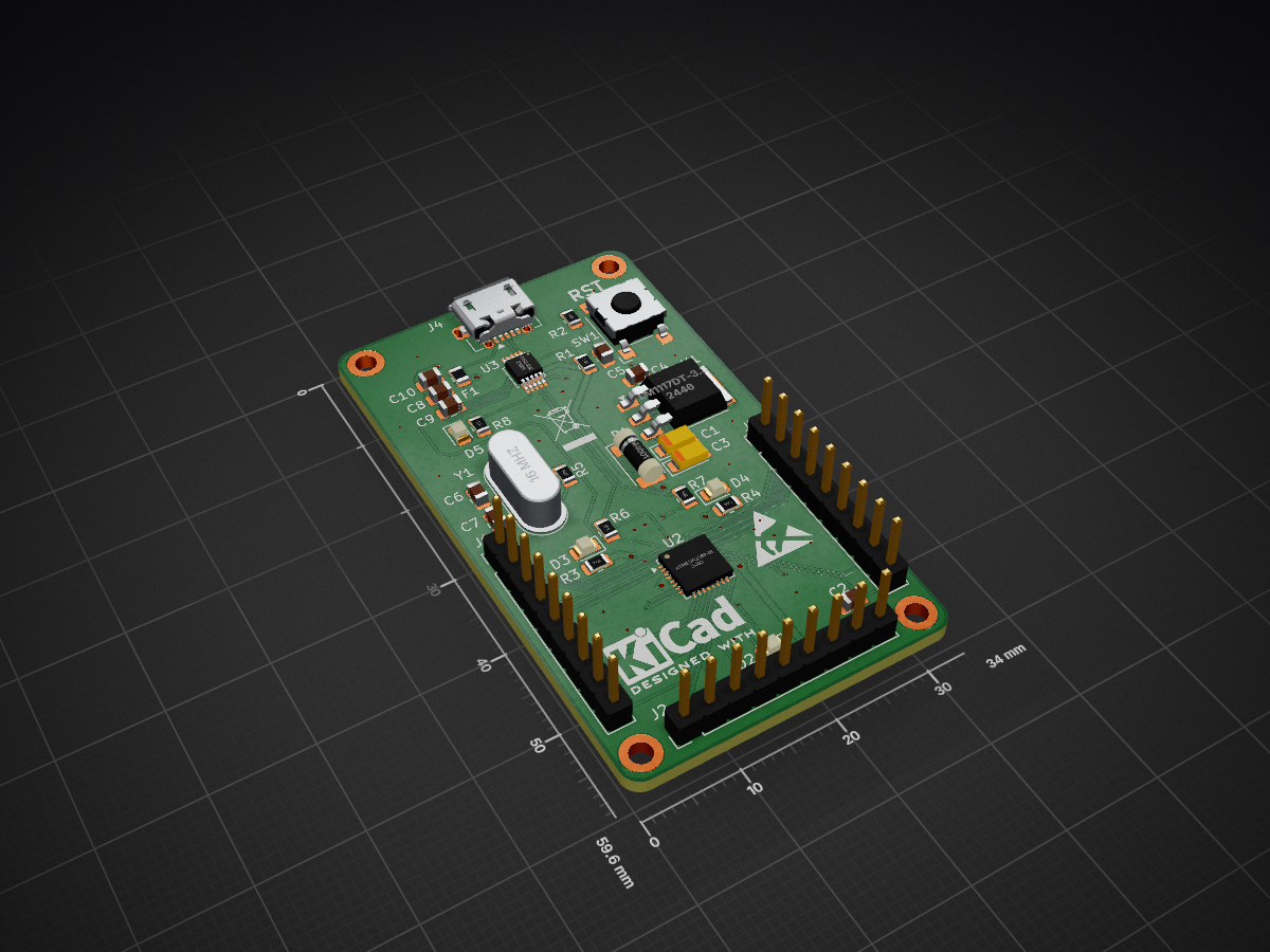
 SushantSaroch13/Arduino-Minimal-Design1
A minimal Arduino-compatible board built around the ATmega328P-M microcontroller with an integrated CH340E USB-to-Serial interface for direct programming via USB.
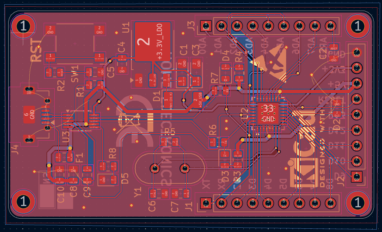
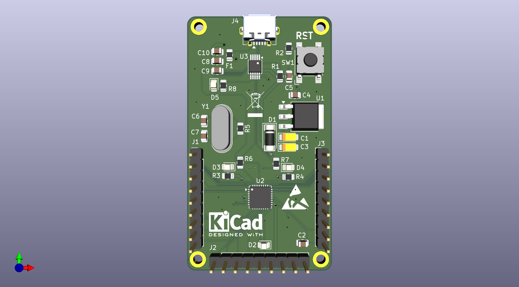
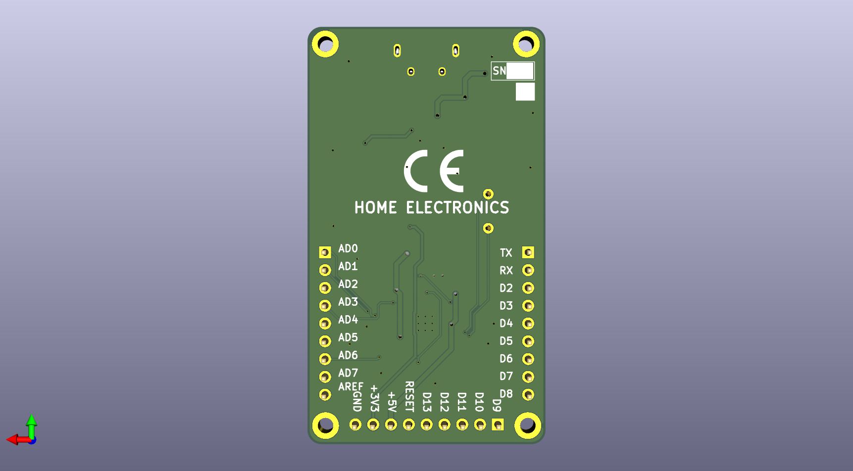
Arduino Minimal Design is an open-source printed circuit board by SushantSaroch13, from the SushantSaroch13/Arduino-Minimal-Design repository on GitHub. It is a 2-layer board of 33.9 × 59.6 mm with 41 parts on 43 nets, routed with 278 tracks and 40 vias.
It is built around the ATMEGA328P-MU, CH340E and LM1117DT-3.3, with the SM4001 among its other parts. Its parts include 10 capacitors, 8 resistors, 5 diodes, 4 connectors and 3 ICs. It belongs with the AVR (ATmega, ATtiny) boards of this library.


A minimal Arduino-compatible board built around the ATmega328P-M microcontroller with an integrated CH340E USB-to-Serial interface for direct programming via USB.
The goal of this project is to demonstrate a compact and practical Arduino hardware implementation using minimal components while maintaining full functionality.
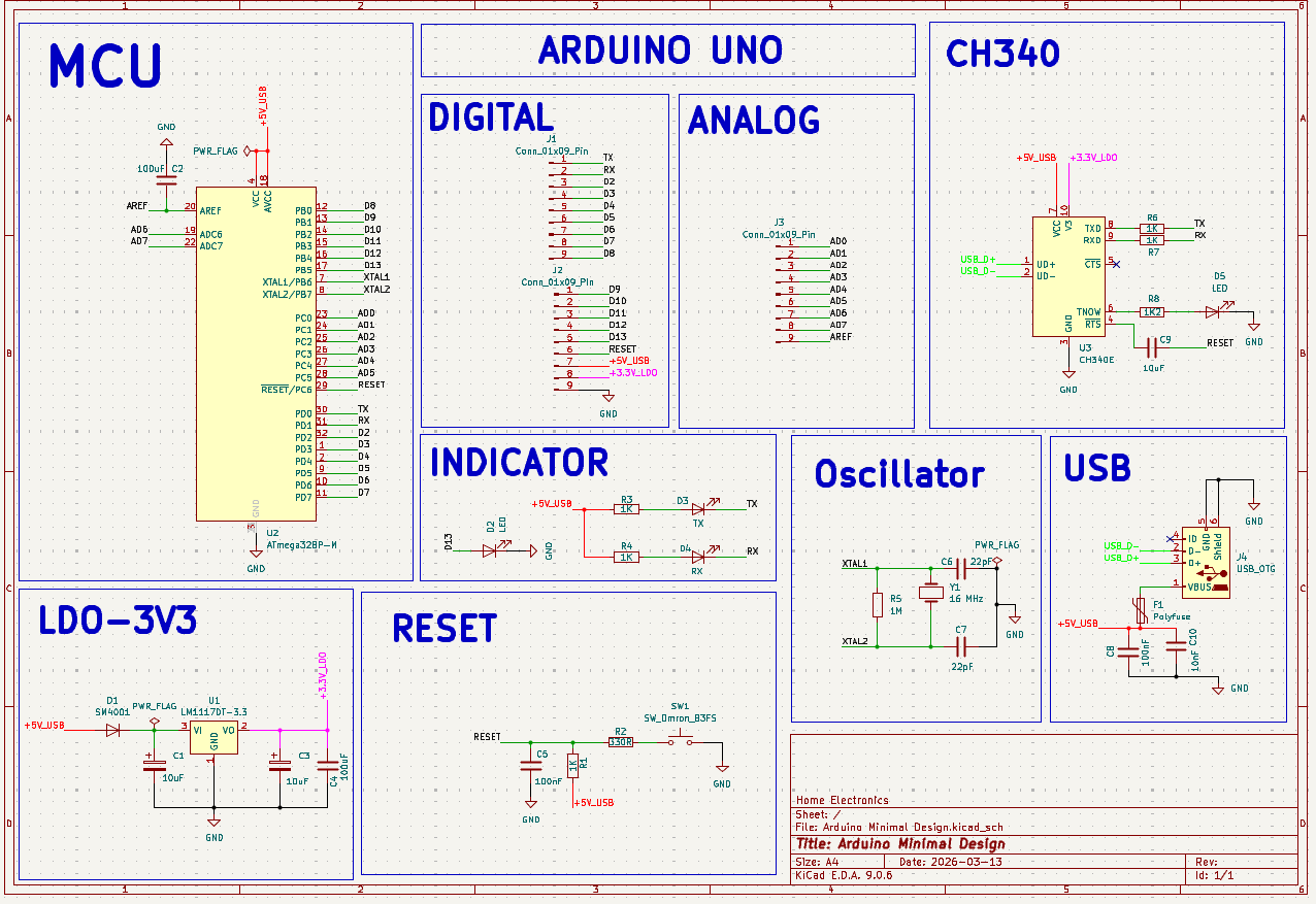
The board consists of four main functional blocks:
1. Microcontroller
2. USB Interface
3. Power Regulation
4. Status Indicators
| Component | Description | Qty |
|---|---|---|
| ATmega328P-M | Microcontroller | 1 |
| CH340E | USB to UART Converter | 1 |
| LM1117DT-3.3 | Voltage Regulator | 1 |
| 16 MHz Crystal | Clock Source | 1 |
| USB Micro Connector | Programming Interface | 1 |
| Polyfuse | USB Protection | 1 |
| SM4001 | Protection Diode | 1 |
| Reset Switch | Push Button Reset | 1 |
| LEDs | Power / TX / RX Indicators | 4 |
| Resistors | Various (330Ω, 1kΩ, 1k2Ω, 1MΩ) | 9 |
| Capacitors | Various (22pF, 100nF, 10uF, 100uF) | 10 |
| Pin Headers | I/O Connections | 3 |
The board can be programmed directly through the USB interface.
Steps:
This board can be used for:
Sushant Saroch Electronics & Communication Engineer Focus: Embedded Systems • PCB Design • Hardware Development
⭐ If you find this project useful, consider starring the repository.
| Qty | Value | Footprint | References |
|---|---|---|---|
| 5 | 1K | Resistor_SMD:R_0805_2012Metric | R1, R3, R4, R6, R7 |
| 3 | Conn_01x09_Pin | Connector_PinHeader_2.54mm:PinHeader_1x09_P2.54mm_Vertical | J1, J2, J3 |
| 2 | 100nF | Capacitor_SMD:C_0805_2012Metric | C5, C8 |
| 2 | 100uF | Capacitor_SMD:C_0805_2012Metric | C2, C4 |
| 2 | 10uF | Capacitor_Tantalum_SMD:CP_EIA-3216-12_Kemet-S_HandSolder | C1, C3 |
| 2 | 22pF | Capacitor_SMD:C_0805_2012Metric | C6, C7 |
| 2 | LED | LED_SMD:LED_0805_2012Metric | D2, D5 |
| 1 | 10nF | Capacitor_SMD:C_0805_2012Metric | C10 |
| 1 | 10uF | Capacitor_SMD:C_0805_2012Metric | C9 |
| 1 | 16 MHz | Crystal:Crystal_HC49-4H_Vertical | Y1 |
| 1 | 1K2 | Resistor_SMD:R_0805_2012Metric | R8 |
| 1 | 1M | Resistor_SMD:R_0805_2012Metric | R5 |
| 1 | 330R | Resistor_SMD:R_0805_2012Metric | R2 |
| 1 | ATmega328P-M | Package_DFN_QFN:QFN-32-1EP_5x5mm_P0.5mm_EP3.3x3.3mm_ThermalVias | U2 |
| 1 | CH340E | Package_SO:MSOP-10_3x3mm_P0.5mm | U3 |
| 1 | LM1117DT-3.3 | Package_TO_SOT_SMD:TO-252-3_TabPin2 | U1 |
| 1 | Polyfuse | Fuse:Fuse_0805_2012Metric | F1 |
| 1 | RX | LED_SMD:LED_0805_2012Metric | D4 |
| 1 | SM4001 | Diode_SMD:D_MELF | D1 |
| 1 | SW_Omron_B3FS | Button_Switch_SMD:SW_SPST_Omron_B3FS-100xP | SW1 |
| 1 | TX | LED_SMD:LED_0805_2012Metric | D3 |
| 1 | USB_OTG | Connector_USB:USB_Micro-AB_Molex_47590-0001 | J4 |
The 33 most common of 41 parts.
MatheusCipolotti/STM32_Codes
Repository dedicated to storing programming on STM32


oomlout/oomlout_oomp_project_bot_v_2


jsenzel1/supra
is multimode Eurorack module with 4 different experiments in long term time. you can run up to 2 modes at once. use the 4 way joystick and buttons to interact with the modes on the oled

baldengineer/C64-Pi-Pico-USB-Keyboard-Adapter
Adapter to use serial/usb/wireless keyboard to type on C64

It measures 33.9 × 59.6 mm and has 2 copper layers, 1.6 mm thick.
41 parts, built around the ATMEGA328P-MU, CH340E, LM1117DT-3.3 and SM4001. The full list of its parts is on this page, with links to each part's symbol and footprint where PCBKit's library has them.
From the SushantSaroch13/Arduino-Minimal-Design repository on GitHub, at the commit this page was made from: the board is Arduino Minimal Design.kicad_pcb and its schematic Arduino Minimal Design.kicad_sch. PCBKit opens the board in the browser, with nothing to install.
Its repository states no licence, so its author keeps all rights: ask SushantSaroch13 before reusing the design.