

2 layers231.1 × 106.7 mm
 SukkoPera/OpenAmigaMouseTrigger27
Control Amiga add-on boards through mouse buttons
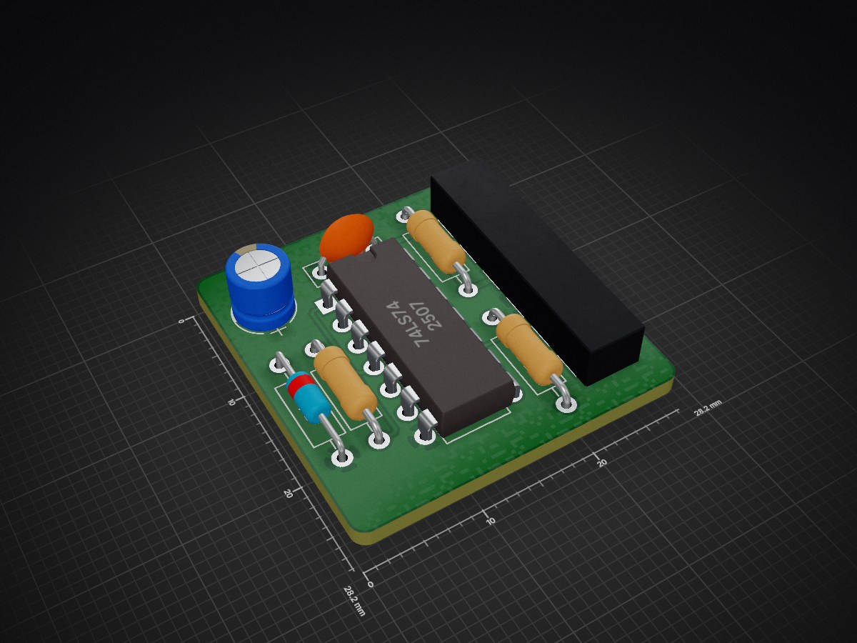
OpenAmigaMouseTrigger is an open-source printed circuit board by SukkoPera, from the SukkoPera/OpenAmigaMouseTrigger repository on GitHub. It is a 2-layer board of 28.2 × 28.2 mm with 11 parts on 7 nets, routed with 63 tracks and 4 vias.
It is built around the 74LS74PC. Its parts include 4 resistors, 4 connectors, 2 capacitors and 1 IC. It belongs with the retro computing and games boards of this library.
OpenAmigaMouseTrigger is an Open Hardware PCB that allows using the state of the mouse buttons at power-up of an Amiga computer to trigger features of other boards, instead of using physical switches. This is mainly useful for controlling a Kickstart Switcher or a Drive Switcher.
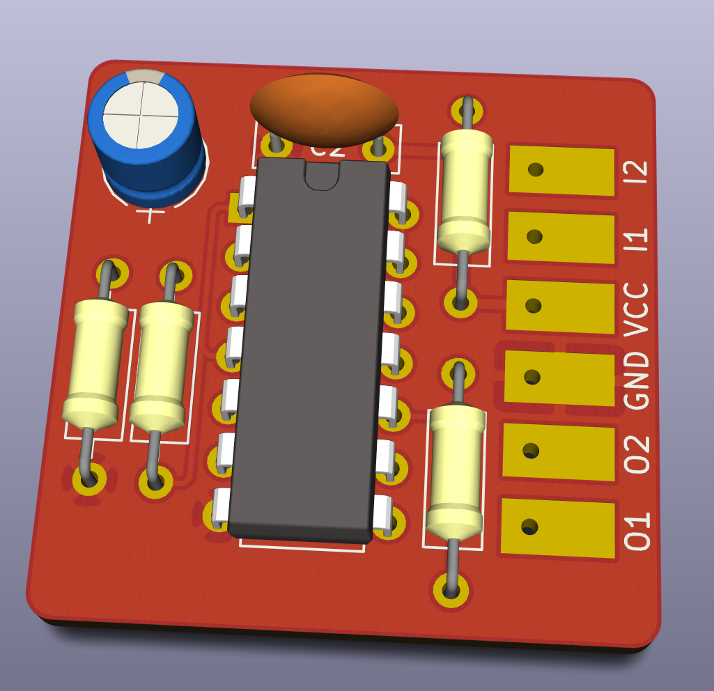
If you install a Kickstart Switcher in your Amiga, you might not want to drill a hole in its venerable case in order to install a switch to select the Kickstart of your choice. Back in the day, it was common to do your selection by holding or not the left mouse button at power-up. OpenAmigaMouseTrigger is a reimplementation of this mechanism on a small isolated board, so that you can use it to trigger anything you want, and not be limited to Kickstarts or even to Amiga computers.
OpenAmigaMouseTrigger also features a second channel, so you can generate up to four different signal combinations.
Solder all components to the board. No particular order is recommended, but starting with the smaller components might be a good idea.
Connect the signals you want to sample at power-up to I1 and I2. Connect the signals you want to drive to O1 and O2. Install R1 and R2 if the input signal needs pull-up resistors.
OpenAmigaMouseTrigger was designed to work with OpenKickstartSwitcher. You can also use it in other scenarios, but the default component values were tuned for this case. While it would be great to use both mouse buttons as input signals, the right mouse button is not usable for this, probably because of how the Amiga sampling circuit was designed. I suggest to use the port 2 joystick fire button as the second selection signal. This is ideal if you put DiagROM + Kickstart 1.3 + Kickstart 3.1 on your OpenKickstartSwitcher, since you won't use DiagROM too often, and you'll be able to select the other two ROMs with the left mouse button.
If your mouse buttons already are used for boot menus or similar, you can use port 2 joystick directions instead. No movement of the joystick will launch your default ROM, you'll be able to select the other two ROMs by holding your joystick in the direction of your choice. Note that to be able to choose between four ROMs, the fourth direction will have to be diagonal, so you have to pick two adjacent directions . Signal 1 is Up, signal 2 is Down, signal 3 is Left, and signal 4 is Right, see image for reference 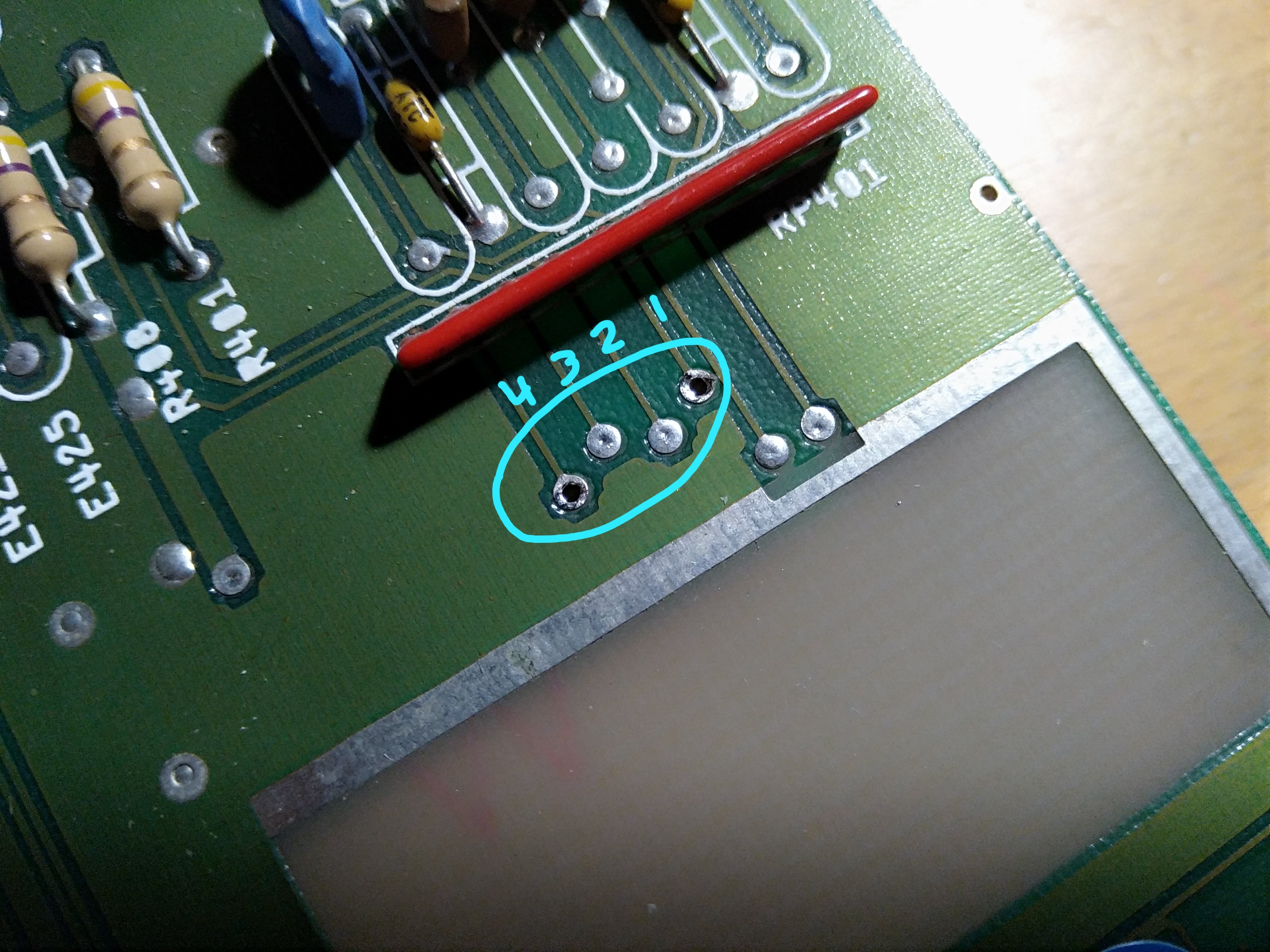
R4 is a bleeder resistor used to discharge C1 quickly when power is removed, be sure to allow at least 4-5 seconds before turning your system back on.
If you use OpenAmigaMouseTrigger in a different scenario, you might want to alter the sampling delay at power-up. This can be done by changing the values of C1 and R3, which form a simple RC network which drives the flip-flip clock signal. The default values will yield a delay or around 50 us, which is quite good for the Amiga (it has a power-on reset pulse after about 100 us) but note that actual capacitor values may differ a lot from the nominal capacity, even 20%, so you might need to do some tweaking. You might also want to experiment with different values of R4, if your C1 has a largely different capacity.
OpenAmigaMouseTrigger is Open Hardware. If you make any modifications to the board, please contribute them back.
If you want to get some boards manufactured, you can get them from PCBWay through this link:

You get my gratitude and cheap, professionally-made and good quality PCBs, I get some credit that will help with this and other projects. You won't even have to worry about the various PCB options, it's all pre-configured for you!
Also, if you still have to register, you can use this link to get some bonus initial credit (and yield me some more).
You can also buy me a coffee if you want:

| Qty | Value | Footprint | References |
|---|---|---|---|
| 2 | 22k | Resistors_THT:R_Axial_DIN0207_L6.3mm_D2.5mm_P10.16mm_Horizontal | R1, R2 |
| 1 | 100n | Capacitors_THT:C_Disc_D7.0mm_W2.5mm_P5.00mm | C2 |
| 1 | 10u | Capacitors_THT:CP_Radial_D5.0mm_P2.00mm | C1 |
| 1 | 330k | Resistors_THT:R_Axial_DIN0207_L6.3mm_D2.5mm_P10.16mm_Horizontal | R4 |
| 1 | 4.7k | Resistors_THT:R_Axial_DIN0207_L6.3mm_D2.5mm_P10.16mm_Horizontal | R3 |
| 1 | 74LS74 | Housings_DIP:DIP-14_W7.62mm | U1 |
| 1 | INPUT_SIGNALS | OpenAmigaMouseTrigger:LoosePads-2 | J1 |
| 1 | OSHW_LOGO | w_logo:Logo_copper_OSHW_6x6mm | J99 |
| 1 | OUTPUT | OpenAmigaMouseTrigger:LoosePads-2 | J2 |
| 1 | POWER | OpenAmigaMouseTrigger:LoosePads-2 | J3 |

jotego/jtcores
FPGA cores compatible with multiple arcade game machines and KiCAD schematics of arcade games. Working on MiSTer FPGA/Analogue Pocket


Nakazoto/CenturionComputer
This is just a simple backup of all the files related to the Centurion that I have stored on my HD. The Wiki itself has far more in-depth information about the Centurion and it's individual cards.

schlae/comix-35
The COMIX-35 is an improved clone of the COMX-35 1802 home computer


monotech/NuXT
MicroATX Turbo XT Motherboard, with VGA, Floppy, CF, Serial

It measures 28.2 × 28.2 mm and has 2 copper layers, 1.6 mm thick.
11 parts, built around the 74LS74PC. The full list of its parts is on this page, with links to each part's symbol and footprint where PCBKit's library has them.
From the SukkoPera/OpenAmigaMouseTrigger repository on GitHub, at the commit this page was made from: the board is OpenAmigaMouseTrigger.kicad_pcb. PCBKit opens the board in the browser, with nothing to install.
Its repository states no licence, so its author keeps all rights: ask SukkoPera before reusing the design.