2 layers66.5 × 37.3 mm
LoRa Boat Controller
SpaceCadetJ/LoRa-Autonomous-Boat
An embedded-systems project spanning STM32 firmware, LoRa communication, PCB reconstruction and a documented V2 redesign.
44 parts

 SpaceCadetJ/LoRa-Autonomous-Boat
An embedded-systems project spanning STM32 firmware, LoRa communication, PCB reconstruction and a documented V2 redesign.
IMU PLACEMENT STUDY is an open-source printed circuit board by SpaceCadetJ, from the SpaceCadetJ/LoRa-Autonomous-Boat repository on GitHub. It is a 2-layer board of 80 × 46 mm with 130 parts on 71 nets, routed with 1,077 tracks and 166 vias.
It is built around the STM32F446RET6, 74AHCT1G125SE and R1240N001B-TR-FE, with the TPS54202DDC, ICM-20948 and PCA9306DCTR among its other parts. Its parts include 42 capacitors, 38 resistors, 11 ICs, 11 diodes and 7 connectors. It belongs with the sensors and measurement boards and the STM32 boards of this library.


An embedded-systems project spanning STM32 firmware, LoRa communication, PCB reconstruction and a documented V2 redesign. The original university boat controller is preserved as V1; the next vehicle node and a voice/text/location handheld are under development.
Current milestone: engineering review edition. The schematics, source code, parts and build procedures are available for inspection. V2 is not fabrication-ready, and the preserved V1 firmware build is not hardware-qualified.
Portfolio case study · Application handbook · Build and assembly guide · Latest verification · Project history
| Existing controller | Developing controller |
|---|---|
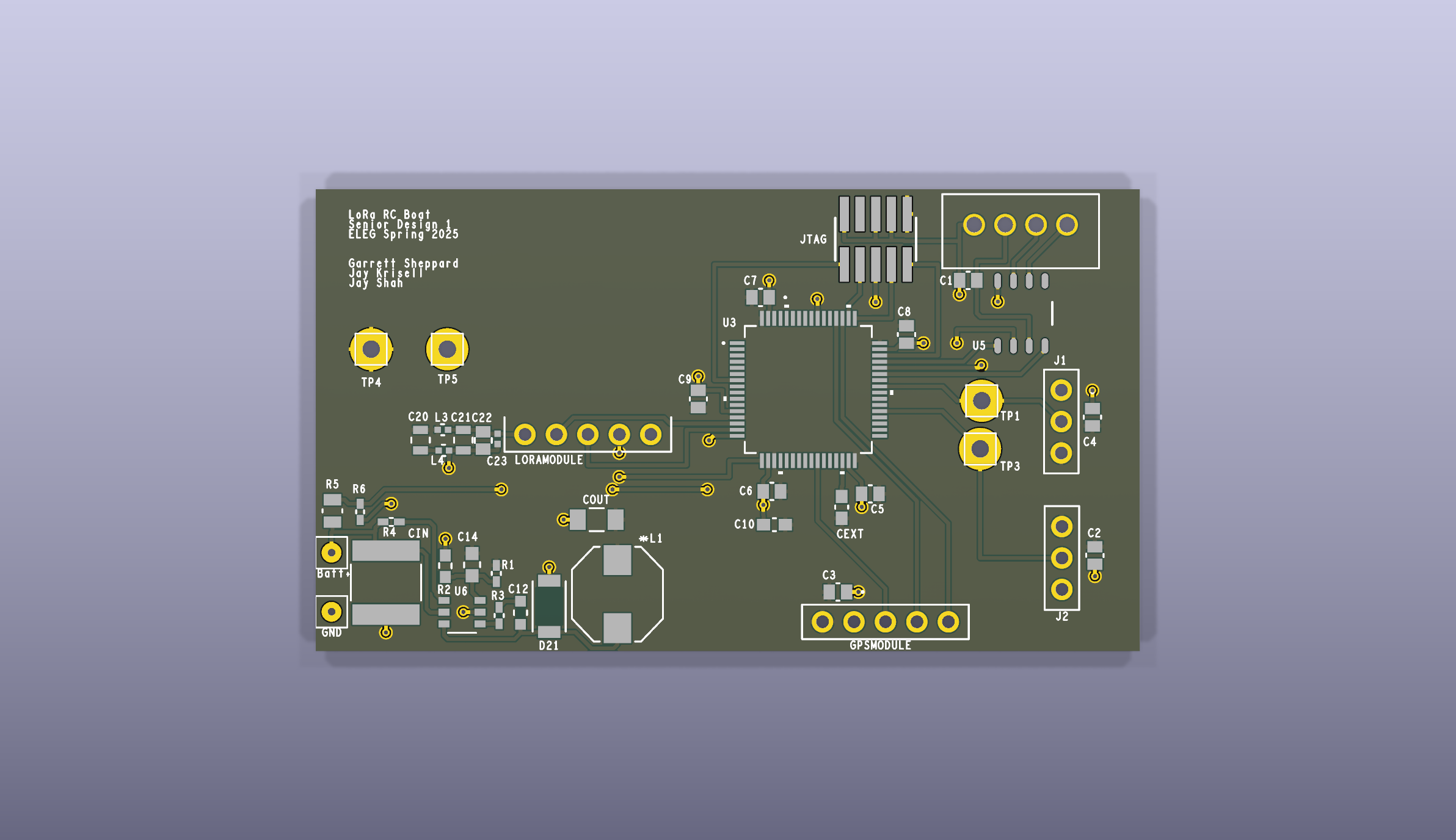 | 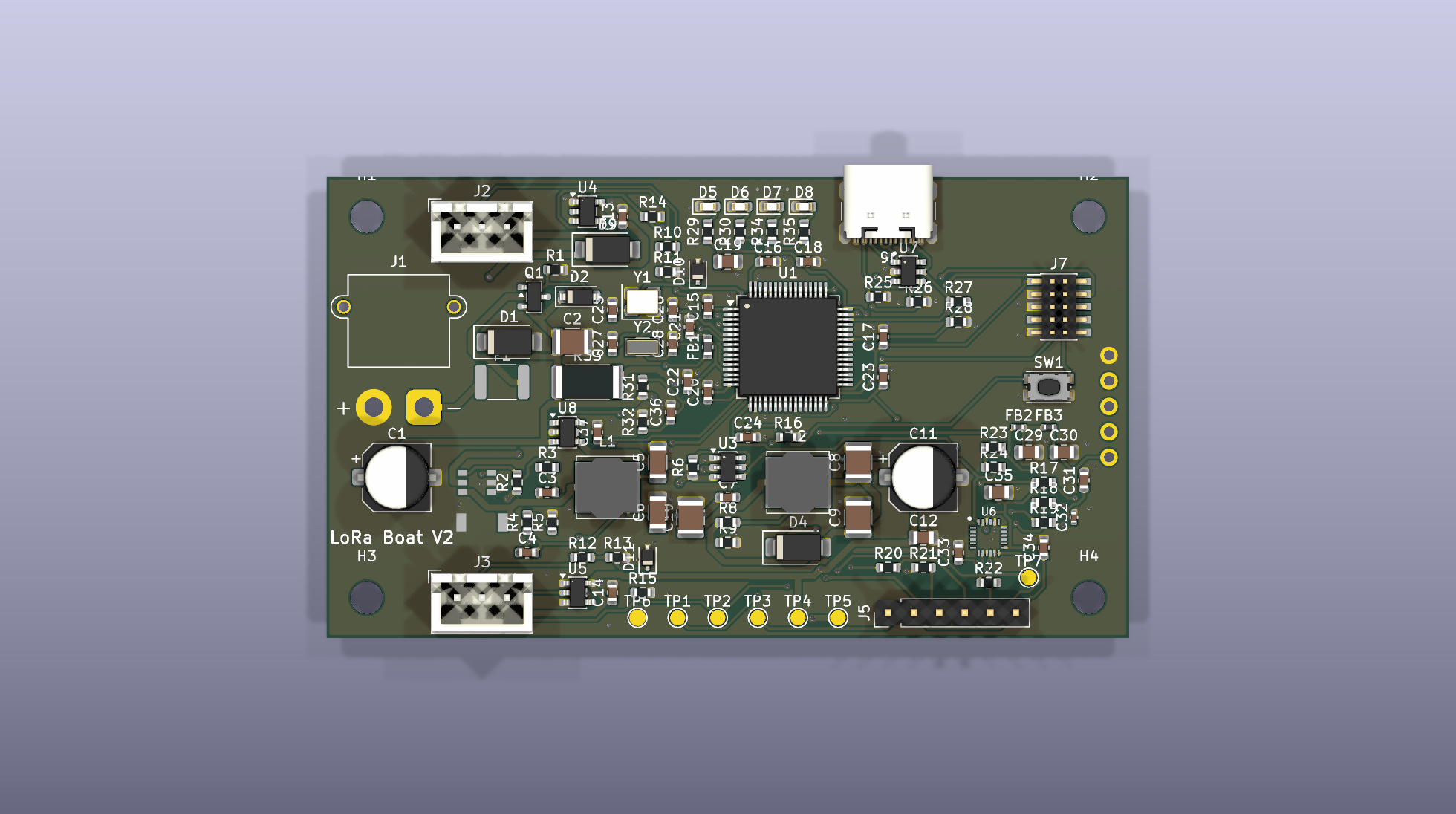 |
| V1: 44 physical components, reconstructed from original fabrication evidence | V2: 118 physical references, 80 × 46 mm board draft |
These are CAD renders. They do not establish that the V2 board has been manufactured or tested.
Clone or download the repository, then open pm/index.html locally. For the complete interactive workspace with searchable BOMs, datasheets, drawings, connector evidence and assembly/programming guides:
node pm/tools/serve.mjsOpen http://127.0.0.1:8765/pm/. The viewer runs locally and requires no account or package installation. GitHub displays the HTML source; it does not run the viewer from a repository file link. See viewer instructions.
The portfolio handoff and structured project data provide captions, asset paths, result evidence and claim boundaries for a portfolio site.
flowchart LR
  Handset[External handset] <-->|LoRa radio link| Radio[Reyax UART radio]
  Radio <-->|UART| MCU[STM32F446 vehicle controller]
  GPS[GNSS receiver] -->|NMEA UART| MCU
  MCU -->|PWM| ESC[Propulsion ESC]
  MCU -->|PWM| Servo[Steering servo]
  Battery[Battery and regulation] --> MCU
V1 firmware is bare-metal C using STM32 HAL/CMSIS, with UART radio commands, GPS parsing and two PWM outputs. The original handset source is not included. The current code has known failsafe, parsing and pin-role issues documented in the firmware audit.
Hardware originated in Cadence OrCAD/Allegro and has been reconstructed in KiCad 9. Python tools generate and inspect schematics, compare complete pin groups and prepare assembly evidence. The viewer uses HTML, CSS and JavaScript with embedded project data; Node.js builds and validates it. GitHub Actions separates portable repository checks from optional native CAD and firmware jobs.
V2 adds draft provisions for protected power, a separate actuator rail, sensing and USB/debug access. The separate Stage A diagnostic now builds for board identity and inactive actuator outputs. Corrected control firmware, autonomous navigation and the proposed voice/text/location handheld remain development targets. Voice airtime and RC coexistence must be validated before choosing handheld hardware.
| Deliverable | Recorded result | Evidence |
|---|---|---|
| Readable schematic set | 15 annotated pages, visually inspected | V1 PDF, V2 PDF, visual review |
| Electrical preservation | All 172 V1 and 361 V2 pins preserved through the presentation changes | Independent quality evidence |
| V1 firmware reconstruction | Two same-host builds produced identical ELF/HEX/BIN hashes; 36,528-byte BIN | Build record |
| Ordering and assembly | BOM reconciliation, held-part decisions, one-board/five-board candidate lists and assembly maps | Ordering guide |
| Navigation and documentation | Searchable parts, selected datasheets, V1 connector atlas, source evidence and version-specific programming guides | Workspace, build guide |
| Reproducible review | Regression tests, source hashes, native reports and preserved before/after evidence | Review workflow |
The integrated V2 ground repair reduces three unconnected PCB items to zero, with zero ordinary DRC errors and unchanged warning/parity counts. The fresh native review preserves all 533 electrical pins. One V2 ERC warning remains; the strict review also flags the intentional PCB change against its older preservation baseline. Six component-limit blockers require circuit corrections before fabrication. No range, voice or autonomous-navigation performance is claimed by these software/CAD results.
Do not run full PCB generation or routing merely to refresh drawings. The schematic-only command preserves the existing PCB, project and BOM. Native KiCad checks require KiCad 9; the V1 build requires the recorded GNU Arm toolchain. No CI job flashes real hardware.
The IMU interface candidate now implements the proposed 1.8 V supply and I2C/interrupt translation in a separately checked schematic. It is available in the V2 viewer; live PCB integration is the next layout task.
The original controller was a University of Arkansas EECS senior-design team project; the repository identifies May 2025 fabrication evidence. The current reconstruction, documentation and review tooling include AI-agent-assisted development. Individual original team contributions should be confirmed before using first-person portfolio claims.
Allegro/ preserves original source evidence. Read provenance and conversion limits before interpreting the reconstructed geometry or inferred drill data. Third-party firmware and tools retain their existing notices; no new project-wide license is granted by this documentation.
| Qty | Value | Footprint | References |
|---|---|---|---|
| 18 | 100nF | Capacitor_SMD:C_0603_1608Metric | C13, C14, C15, C16, C17, C18, C22, C23, C24, C31, C33, C34, C36, C37, C40, C41 +2 |
| 8 | 100R | Resistor_SMD:R_0603_1608Metric | R10, R12, R17, R18, R19, R20, R21, R22 |
| 6 | 100k | Resistor_SMD:R_0603_1608Metric | R1, R6, R8, R14, R15, R39 |
| 4 | 10uF 10V | Capacitor_SMD:C_0805_2012Metric | C19, C29, C30, C35 |
| 4 | 1k | Resistor_SMD:R_0603_1608Metric | R29, R30, R34, R35 |
| 4 | M3 | MountingHole:MountingHole_3.2mm_M3 | H1, H2, H3, H4 |
| 3 | 10k | Resistor_SMD:R_0603_1608Metric | R11, R13, R16 |
| 3 | 4.7k | Resistor_SMD:R_0603_1608Metric | R5, R36, R37 |
| 3 | 5.1k | Resistor_SMD:R_0603_1608Metric | R2, R25, R26 |
| 2 | 10pF C0G | Capacitor_SMD:C_0603_1608Metric | C27, C28 |
| 2 | 10uF 25V | Capacitor_SMD:C_1206_3216Metric | C5, C6 |
| 2 | 10uF 50V | Capacitor_SMD:C_1210_3225Metric | C2, C10 |
| 2 | 15pF C0G | Capacitor_SMD:C_0603_1608Metric | C25, C26 |
| 2 | 2.2k | Resistor_SMD:R_0603_1608Metric | R23, R24 |
| 2 | 2.2uF | Capacitor_SMD:C_0805_2012Metric | C38, C39 |
| 2 | 22uF 16V | Capacitor_SMD:C_1210_3225Metric | C8, C9 |
| 2 | 4.7uH 3A | Inductor_SMD:L_Bourns_SRN6045TA | L1, L2 |
| 2 | 47k | Resistor_SMD:R_0603_1608Metric | R27, R31 |
| 2 | 600R | Inductor_SMD:L_0402_1005Metric | FB2, FB3 |
| 2 | 74AHCT1G125 | Package_TO_SOT_SMD:SOT-23-5 | U4, U5 |
| 2 | PESD5V0S1BA | Diode_SMD:D_SOD-323 | D10, D11 |
| 2 | SS34 | Diode_SMD:D_SMA | D4, D9 |
| 1 | +3V3 | TestPoint:TestPoint_Pad_D1.5mm | TP3 |
| 1 | 0.02R 1W | Resistor_SMD:R_2512_6332Metric | R33 |
| 1 | 100nF 50V | Capacitor_SMD:C_0603_1608Metric | C3 |
| 1 | 100uF 10V | Capacitor_SMD:CP_Elec_6.3x7.7 | C11 |
| 1 | 10uF 16V | Capacitor_SMD:C_0805_2012Metric | C12 |
| 1 | 12V | Diode_SMD:D_SOD-123 | D2 |
| 1 | 13.3k | Resistor_SMD:R_0603_1608Metric | R9 |
| 1 | 15k | Resistor_SMD:R_0603_1608Metric | R4 |
| 1 | 1uF | Capacitor_SMD:C_0603_1608Metric | C21 |
| 1 | 200k | Resistor_SMD:R_0603_1608Metric | R38 |
| 1 | 22k | Resistor_SMD:R_0603_1608Metric | R28 |
| 1 | 32.768kHz | Crystal:Crystal_SMD_3215-2Pin_3.2x1.5mm | Y2 |
| 1 | 3A | Fuse:Fuse_1812_4532Metric | F1 |
| 1 | 4.7uF 10V | Capacitor_SMD:C_0603_1608Metric | C20 |
| 1 | 470pF | Capacitor_SMD:C_0603_1608Metric | C4 |
| 1 | 47pF | Capacitor_SMD:C_0402_1005Metric | C32 |
| 1 | 47uF 50V | Capacitor_SMD:CP_Elec_6.3x7.7 | C1 |
| 1 | 51R | Resistor_SMD:R_0603_1608Metric | R3 |
| 1 | 6.8k | Resistor_SMD:R_0603_1608Metric | R32 |
| 1 | 600R | Inductor_SMD:L_0603_1608Metric | FB1 |
| 1 | 8MHz | Crystal:Crystal_SMD_3225-4Pin_3.2x2.5mm | Y1 |
| 1 | AO3401A | Package_TO_SOT_SMD:SOT-23 | Q1 |
| 1 | BATTERY XT30 | Connector_AMASS:AMASS_XT30PW-M_1x02_P2.50mm_Horizontal | J1 |
| 1 | CMS06 | LoRa_Boat_Controller:M-FLAT_TOS-L | D3 |
| 1 | ESC | Connector_JST:JST_XH_B3B-XH-A_1x03_P2.50mm_Vertical | J2 |
| 1 | ESC_PWM | TestPoint:TestPoint_Pad_D1.5mm | TP1 |
| 1 | FAULT red | LED_SMD:LED_0603_1608Metric | D8 |
| 1 | FIX yellow | LED_SMD:LED_0603_1608Metric | D7 |
| 1 | GND | TestPoint:TestPoint_Pad_D1.5mm | TP6 |
| 1 | GNSS | Connector_PinHeader_2.54mm:PinHeader_1x06_P2.54mm_Vertical | J5 |
| 1 | ICM-20948 | LoRa_Boat_Controller_V2:QFN-24_3x3mm_P0.4mm_NoEP | U6 |
| 1 | INA180A1 | Package_TO_SOT_SMD:SOT-23-5 | U8 |
| 1 | LINK blue | LED_SMD:LED_0603_1608Metric | D6 |
| 1 | LoRa RYLR998 | LoRa_Boat_Controller:CONN5_1LFBN-RC_SUL | J4 |
| 1 | PCA9306DCTR | LoRa_Boat_Controller_V2:TI_DCT0008A_PCA9306_3x3mm_P0.65mm | U10 |
| 1 | PPS | TestPoint:TestPoint_Pad_D1.5mm | TP7 |
| 1 | PWR green | LED_SMD:LED_0603_1608Metric | D5 |
| 1 | R1240N001B-TR-FE | LoRa_Boat_Controller:SOT-23-6W_PE-SOT23-6W-0512_NMD | U2 |
| 1 | RESET | Button_Switch_SMD:SW_Push_1P1T_NO_CK_KMR2 | SW1 |
| 1 | SERVO | Connector_JST:JST_XH_B3B-XH-A_1x03_P2.50mm_Vertical | J3 |
| 1 | SERVO_PWM | TestPoint:TestPoint_Pad_D1.5mm | TP2 |
| 1 | SMAJ33A | Diode_SMD:D_SMA | D1 |
| 1 | SN74AXC1T45DBVR | Package_TO_SOT_SMD:SOT-23-6 | U11 |
| 1 | STM32F446RET6 | Package_QFP:LQFP-64_10x10mm_P0.5mm | U1 |
| 1 | SWD | Connector_PinHeader_1.27mm:PinHeader_2x05_P1.27mm_Vertical_SMD | J7 |
| 1 | TLV75518PDBVR | Package_TO_SOT_SMD:SOT-23-5 | U9 |
| 1 | TPS54202 | Package_TO_SOT_SMD:TSOT-23-6 | U3 |
| 1 | USB-C | Connector_USB:USB_C_Receptacle_GCT_USB4105-xx-A_16P_TopMnt_Horizontal | J6 |
| 1 | USBLC6-2SC6 | Package_TO_SOT_SMD:SOT-23-6 | U7 |
| 1 | VIN_RAW | TestPoint:TestPoint_Pad_D1.5mm | TP5 |
| 1 | VSERVO | TestPoint:TestPoint_Pad_D1.5mm | TP4 |
SpaceCadetJ/LoRa-Autonomous-Boat
An embedded-systems project spanning STM32 firmware, LoRa communication, PCB reconstruction and a documented V2 redesign.

hansenkw/Vu-LED-Meter
This is a decorative LED that shines based on the audio input through the 3.5mm audio jack connector. The design is a 2-layer printed circuit board based on Great Scott Vu LED Meter with few modifications as noted in…

Twistiee/rcm
A CAN-controlled relay driver for a car. 21 universal channels, each of which is simultaneously a low-side output and an input — so the same board builds as a relay controller or as a switch panel, decided in firmware…

FluYVy/Modular-Electronics-Toolkit
This project is a diploma thesis done at the HTL Rankweil. It aims to provide future students with a better way to understand and work with different sensors and actuators.

rivotmotors-rnd/ECU_Firmware_V3
RIVOT ECU V3.0 Repo containing STM32F446RE firmware and KiCad PCB hardware designs.

jadenrhee/wigglecam-controller
RP2040 co-processor board for a 4-lens wigglegram camera: constant-current flash, controls, battery telemetry, Pi 5 I2C interface. 4-layer, DRC-clean, fab-ready.


Catsarepro21/hackpad_v2
Wireless ESP32-S3 macropad: KiCad PCB, case STEP models, and Gerber/drill fabrication files.
It measures 80 × 46 mm and has 2 copper layers, 1.6 mm thick.
130 parts, built around the STM32F446RET6, 74AHCT1G125SE, R1240N001B-TR-FE and TPS54202DDC. The full list of its parts is on this page, with links to each part's symbol and footprint where PCBKit's library has them.
From the SpaceCadetJ/LoRa-Autonomous-Boat repository on GitHub, at the commit this page was made from: the board is reviews/codex/imu_placement/study/IMU_PLACEMENT_STUDY.kicad_pcb. PCBKit opens the board in the browser, with nothing to install.
Its repository states no licence, so its author keeps all rights: ask SpaceCadetJ before reusing the design.