Skip to the content
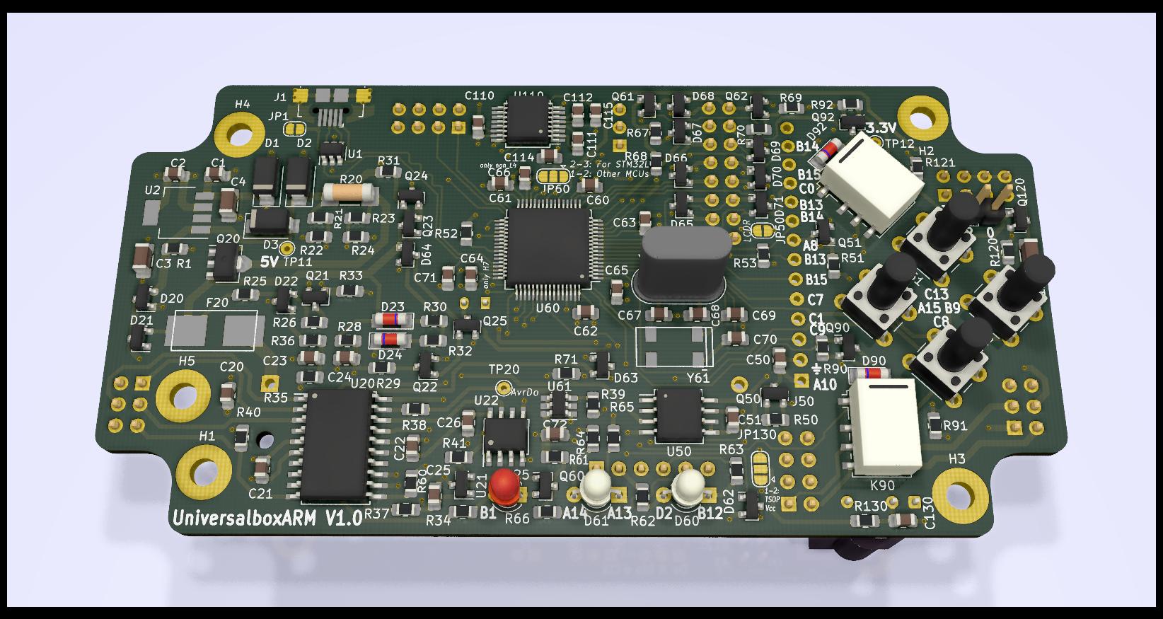
4 layers112 × 57 mmUniversalboxArm1-0, the printed circuit board in 3D

PCB for experimenting with a STM32

Size
112 × 57 mm
Copper layers
4
Thickness
1.6 mm
Parts
170
Nets
157
Pads
588
Tracks, vias
1,783, 211
Pours
4
Routed
Yes
KiCad
KiCad 5 (file 20171130)
Created
20 Jul 2021
Updated
2 Feb 2026

Overview

UniversalboxArm1-0 is an open-source printed circuit board by Solartraveler, from the Solartraveler/UniversalboxArm repository on GitHub. It is a 4-layer board of 112 × 57 mm with 170 parts on 157 nets, routed with 1,783 tracks and 211 vias.

It is built around the ATTINY861A-SU, MAX3221CPW and LP38693MP-3.3, with the MCP6542-I/P, USBLC6-2SC6 and BSS138 among its other parts. Its parts include 45 resistors, 33 capacitors, 25 diodes, 16 transistors and 11 connectors. It belongs with the STM32 and AVR (ATmega, ATtiny) boards of this library.

Main components

12

README

README.md

UniversalboxArm

Idea

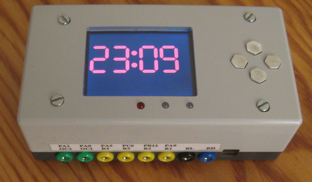
Have a box for experiments and easy testing with a CPU which is more powerful than an AVR (Arduino) and uses less energy than a Raspberry Pi. Then add some common peripherals and fit this into a case.

alt text

alt text

alt text

Features

The following hardware has been added. Not everything is required to be populated on the PCB.

  • Various 64Pin STM32 MCUs possible

    • STM32L452RET (80MHz, 160KiB RAM) tested
  • Runs from USB power

  • Can run from a LiFePO battery and charge it

  • 2x red-green duo LEDs

  • Four buttons

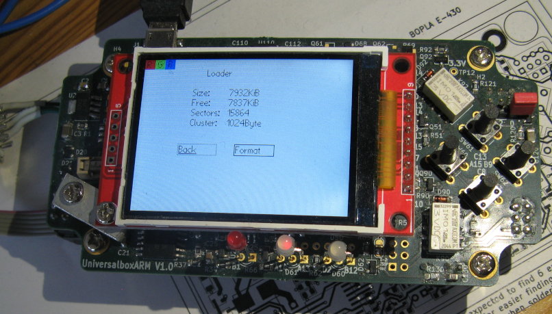
  • LCD socket

    • 128x128 (ST7735, tested), 160x128 (ST7735, untested) or 320x240 (ILI9341, tested) RGB LCDs are possible
  • Four Relays

  • External flash with up to 8MiB

  • RS232 level converter

  • IR receiver

  • WLAN with an ESP-01

  • Two open collector outputs

  • Several ESD protected in and outputs

  • AVR coprocessor for resetting and charge control

Status

Software

DFU loader for the ARM

A loader for the STM32 MCU is feature complete.

  • Can be used by the common dfu-util delivered by the usual Linux distributions (like Debian)

  • Accepts applications within a common .tar file together with some metadata

    • With the STM32L452 having 160KiB RAM, the tar file may be up to 128KiB in size. Needing 2.5KiB overhead for the .tar format and the metadata, the binary may be up to 125.5KiB in size and after starting can use the full 160KiB for code + data. Executing from RAM results in about 80% of the speed compared with executing from flash with the same CPU frequency.
  • The application can be run directly from the RAM or stored into the external flash

    • Transferring to RAM is much faster than writing to the flash. Also there is no worry about the internal flash lifetime.
  • Formats the external flash as FAT filesystem

  • Allows configuring one of the three LCD sizes

    • Configuration is stored on the external flash and can be read by other applications
  • With the four keys and the LCD, applications can be selected from the external flash and run without an USB connection

    • Can set one application as autostarting on power-on
  • Each application can have a short descriptive text and explanation image to be shown on the LCD

    • The text can be up to 1KiB long and is taken from the readme.md of each firmware

    • The image is 3 bit RGB and must have the size of the selected LCD or one of the possible smaller LCDs. Moreover the compressed data needs to fit within 7000byte. Due to RAM constraints, each 4x4 pixel block can not display pixel with more than two different colors.

Firmware for the coprocessor
  • A long press of the left key resets the ARM processor

  • A long press of the right key toggles if a reset should start the DFU bootloader from ST or the application from the flash (most likely the DFU bootloader described above)

  • Supports a SPI communication to the ARM processor

    • ARM processor can request a reset

    • ARM processor can enable a watchdog

  • The battery can be charged

  • A wakeup time for the ARM processor can be set

More software

Software testing all the hardware to be working as intended has been written for the ARM processor and the AVR coprocessor.

There is a implementation for using the 8MiB flash as USB pen drive.

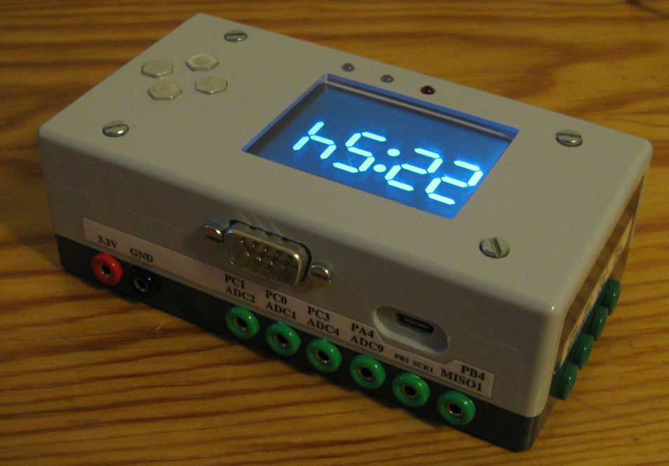
One application implements an NTP client and uses the display as digital clock.

See readme.md

Hardware

The PCB version 1 is working, but a lot of patching is required at several peripherals to use them. With 380µA, the power down consumption is too high, as this would discharge a full battery within 65 days, and then the LiFePo must be considered defective. The required changes are documented. Recreating a PCB version 1 is discouraged. Instead the required changes need to be integrated into a version 2.

Milling the case is done. alt text

See readme.md

Using a breadboard

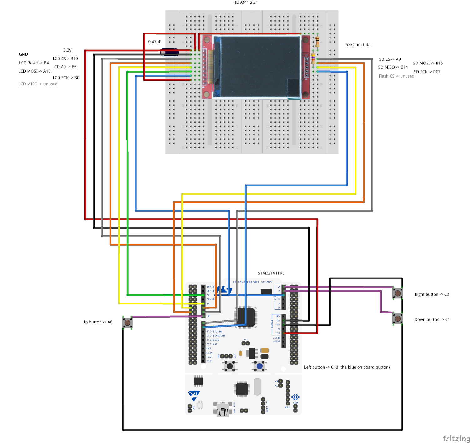
Without soldering an own PCB, some of the apps can be used together with a Nucleo evaluation board from ST. Then it is just a connection of some wires. Instead of the onboard flash, the SD card can be used to store settings. Many of the breakout boards for the LCDs already have a SD card slot on the backside. The serial port is provided by the nucleo board over USB itself. One LED and one button is provided by the nucleo board, thee additional buttons can be connected, everthing else is currently missing support. Currently only the blinky-hal, test-everything and adc-scope apps have been tested on a nucleo with a STM32F411. As the used board with a STM32F411 only has 128KiB of RAM, it will never be possible to load and execute all apps from RAM there. However all could made working when running from flash.

alt text

Parts

170
QtyValueFootprintReferences
17100nFCapacitor_SMD:C_0805_2012Metric_Pad1.15x1.40mm_HandSolderC21, C22, C26, C50, C51, C60, C61, C62, C63, C64, C65, C110, C111, C112, C114, C115 +1
10180ΩResistor_SMD:R_0805_2012Metric_Pad1.15x1.40mm_HandSolderR52, R53, R62, R64, R66, R68, R70, R71, R121, R130
10220kΩResistor_SMD:R_0805_2012Metric_Pad1.15x1.40mm_HandSolderR30, R51, R60, R61, R67, R69, R90, R91, R92, R93
8BSS138Package_TO_SOT_SMD:SOT-23Q21, Q22, Q25, Q60, Q90, Q91, Q92, Q93
7SolderJumper_2_OpenJumper:SolderJumper-2_P1.3mm_Open_RoundedPad1.0x1.5mmJP1, JP50, JP61, JP90, JP91, JP92, JP93
6BAS32LDiode_SMD:D_MiniMELFD23, D24, D90, D91, D92, D93
6PESD5V2S2UTPackage_TO_SOT_SMD:SOT-23D65, D66, D67, D69, D70, D71
5BAT54CPackage_TO_SOT_SMD:SOT-23D20, D21, D62, D63, D64
5IRLML6402Package_TO_SOT_SMD:SOT-23Q23, Q24, Q50, Q51, Q120
5MountingHole_PadMountingHole:MountingHole_3.2mm_M3_PadH1, H2, H3, H4, H5
410µFCapacitor_SMD:C_0805_2012Metric_Pad1.15x1.40mm_HandSolderC1, C2, C20, C23
4IM01Relay_SMD:Relay_DPDT_Omron_G6K-2F-YK90, K91, K92, K93
4SW_SPSTButton_Switch_THT:SW_PUSH_6mm_H13mmSW60, SW61, SW62, SW63
3330ΩResistor_SMD:R_0805_2012Metric_Pad1.15x1.40mm_HandSolderR35, R63, R65
34.7µFCapacitor_SMD:C_0805_2012Metric_Pad1.15x1.40mm_HandSolderC66, C71, C130
3SK14Diode_SMD:D_SMAD1, D2, D3
3TestPointTestPoint:TestPoint_THTPad_D1.5mm_Drill0.7mmTP11, TP12, TP20
2100kΩResistor_SMD:R_0805_2012Metric_Pad1.15x1.40mm_HandSolderR1, R40
2100µFCapacitor_SMD:C_1206_3216Metric_Pad1.33x1.80mm_HandSolderC3, C4
2100ΩResistor_SMD:R_0805_2012Metric_Pad1.15x1.40mm_HandSolderR31, R36
210pFCapacitor_SMD:C_0805_2012Metric_Pad1.15x1.40mm_HandSolderC67, C68
215kΩResistor_SMD:R_0805_2012Metric_Pad1.15x1.40mm_HandSolderR22, R24
222kΩResistor_SMD:R_0805_2012Metric_Pad1.15x1.40mm_HandSolderR26, R39
222pFCapacitor_SMD:C_0805_2012Metric_Pad1.15x1.40mm_HandSolderC69, C70
233kΩResistor_SMD:R_0805_2012Metric_Pad1.15x1.40mm_HandSolderR21, R23
247kΩResistor_SMD:R_0805_2012Metric_Pad1.15x1.40mm_HandSolderR28, R29
256kΩResistor_SMD:R_0805_2012Metric_Pad1.15x1.40mm_HandSolderR50, R120
2Conn_02x04_Odd_EvenConnector_PinHeader_2.54mm:PinHeader_2x04_P2.54mm_VerticalJ62, J91
2IRLML6344Package_TO_SOT_SMD:SOT-23Q61, Q62
2LED_Dual_AACLED_THT:LED_D3.0mm-3D60, D61
2SolderJumper_3_OpenJumper:SolderJumper-3_P1.3mm_Open_RoundedPad1.0x1.5mmJP60, JP130
10.50AMalteM:SFM_OMNI-BLOK_HandsolderF20
110kΩResistor_SMD:R_0805_2012Metric_Pad1.15x1.40mm_HandSolderR32
110nFCapacitor_SMD:C_0805_2012Metric_Pad1.15x1.40mm_HandSolderC24
112kΩResistor_SMD:R_0805_2012Metric_Pad1.15x1.40mm_HandSolderR38
1150ΩResistor_SMD:R_0805_2012Metric_Pad1.15x1.40mm_HandSolderR37
11kΩResistor_SMD:R_0805_2012Metric_Pad1.15x1.40mm_HandSolderR41
13.9ΩResistor_SMD:R_MELF_MMB-0207R20
132768HzCrystal:Crystal_HC49-U_VerticalY60
14.7kΩResistor_SMD:R_0805_2012Metric_Pad1.15x1.40mm_HandSolderR33
14.7µFCapacitor_SMD:C_1206_3216Metric_Pad1.33x1.80mm_HandSolderC120
1470nFCapacitor_SMD:C_0805_2012Metric_Pad1.15x1.40mm_HandSolderC25
1470ΩResistor_SMD:R_0805_2012Metric_Pad1.15x1.40mm_HandSolderR34
18MHzMalteM:Crystal_MP03Y61
19100ΩResistor_SMD:R_0805_2012Metric_Pad1.15x1.40mm_HandSolderR25
1AT45DB641-SPackage_SO:SO-8_5.3x6.2mm_P1.27mmU50
1ATtiny861A-SUPackage_SO:SOIC-20W_7.5x12.8mm_P1.27mmU20
1AVR-ISP-6Connector_PinHeader_2.54mm:PinHeader_2x03_P2.54mm_VerticalJ20
1BCX56-16Package_TO_SOT_SMD:SOT-89-3Q20
1Battery_Cell LiFePoMalteM:Keystone_Holder_1xAA_1015BT20
1Conn_01x02_MaleConnector_PinHeader_2.54mm:PinHeader_1x02_P2.54mm_VerticalJ121
1Conn_01x03_MaleConnector_PinHeader_2.54mm:PinHeader_1x03_P2.54mm_VerticalJ110
1Conn_01x06_FemaleConnector_PinHeader_2.54mm:PinHeader_1x06_P2.54mm_VerticalJ60
1Conn_01x14_FemaleMalteM:LCD_320x240_2.4J50
1Conn_02x03_Odd_EvenConnector_PinHeader_2.54mm:PinHeader_2x03_P2.54mm_VerticalJ90
1Conn_02x04_Counter_ClockwiseMalteM:PinSocket_ESP-01J120
1Conn_02x08_Odd_EvenConnector_PinHeader_2.54mm:PinHeader_2x08_P2.54mm_VerticalJ61
1KTY81-221Package_TO_SOT_THT:TO-92-2TH20
1LEDLED_THT:LED_D3.0mmD25
1LP38693MP-3.3Package_TO_SOT_SMD:SOT-223-5U2
1MAX3221MalteM:SSOP-16_5.3x6.2mm_P0.65mm_HandsolderU110
1MCP6542Package_SO:SOIC-8_3.9x4.9mm_P1.27mmU22
1MCP65R41T-1202EPackage_TO_SOT_SMD:SOT-23-6_HandsolderingU61
1PESD24V2S2UTPackage_TO_SOT_SMD:SOT-23D68
1REF3020Package_TO_SOT_SMD:SOT-23U21
1STM32L452RETxMalteM:LQFP-64_10x10mm_P0.5mm_HandsolderingU60
1TL431DBZPackage_TO_SOT_SMD:SOT-23D22
1TSOP312xxOptoDevice:Vishay_CAST-3PinU130
1USBLC6-2SC6Package_TO_SOT_SMD:SOT-23-6U1
1USB_B_MicroMalteM:USB_Micro-B_Amtek-MIUSB-F5M-BBX-U_HandsolderJ1

Similar boards

  • 4 layers97 × 97.4 mmQEdge UI, the printed circuit board in 3D

    QEdge UI

    qinno/qEdge-UI

    qedge+ is the industry's low power design alternative to the standard PC approach. qEdge-UI is part of qEdge+ and consists of a RaspBerry Pico with LCD, touch screen and keys and an 868MHz LoRa radio module.

    170 parts3
  • 2 layers90 × 56 mmLedspiel, the printed circuit board in 3D

    Ledspiel

    Solartraveler/led-toybox

    Some RGB LEDs, some sound in a case give a good toy for kids

    163 parts
  • 2 layers34 × 46 mmESPDali, the printed circuit board in 3D

    ESPDali

    petrinm/ESP32Dali

    Interface with DALI compatible lighting devices using ESPHome project

    46 parts11MIT
  • 2 layers181 × 137.5 mmWaffle, the printed circuit board in 3D

    Waffle

    Mozzie-AU/LeafOBC-WafflePlate

    Reverse engineering the "waffle plate" power module from the 2012 Nissan Leaf on-board charger (OBC), with the goal of building a functional replica from regular, off-the-shelf components.

    312 partsCERN-OHL-S-2.0
  • 2 layers80 × 60 mmTwo phase charging, the printed circuit board in 3D

    Two phase charging

    HuntieDK/BMW-i3-two-phase-charging

    Extends the BMW i3 60Ah BEV/REX charging to use two phases

    73 parts8MIT
  • 2 layers100 × 100 mmSynchro2, the printed circuit board in 3D

    Synchro2

    waynegramlich/synchro_drive_motor_driver_pcb

    Dual motor drive for dual motor synchro drive PCB

    98 parts
  • 2 layers100 × 100 mmNeuromorphic ir sensor tht, the printed circuit board in 3D

    Neuromorphic ir sensor tht

    RyanHailey21/neuromorphic-IR-hand-assembled

    All through-hole re-implementation of the Rev A neuromorphic IR event sensor: no SMD parts, solderable with a basic iron.

    102 parts
  • 2 layers78 × 61 mmMicromouse, the printed circuit board in 3D

    Micromouse

    F-Sakashita/Micromouse

    85 parts1

Questions

How big is the UniversalboxArm1-0 PCB?

It measures 112 × 57 mm and has 4 copper layers, 1.6 mm thick.

What parts does the UniversalboxArm1-0 use?

170 parts, built around the ATTINY861A-SU, MAX3221CPW, LP38693MP-3.3 and MCP6542-I/P. The full list of its parts is on this page, with links to each part's symbol and footprint where PCBKit's library has them.

Where can I download the UniversalboxArm1-0 KiCad files?

From the Solartraveler/UniversalboxArm repository on GitHub, at the commit this page was made from: the board is schematic/UniversalboxArm1-0.kicad_pcb. PCBKit opens the board in the browser, with nothing to install.

Can I use the UniversalboxArm1-0 design in my own project?

Its repository states no licence, so its author keeps all rights: ask Solartraveler before reusing the design.