2 layers77.6 × 116.3 mm

 SkyRizzAI/SkyRizz-ESPSOL
An open-hardware, coin-sized ESP32-S3 development board with an on-board secure element, 6-axis IMU, PDM microphone, buzzer, USB-C, and Li-Po charging — all on a 40.6 mm (1.6") round, 2-layer PCB.
SkyRizz ESPSOL is an open-source printed circuit board by SkyRizzAI, from the SkyRizzAI/SkyRizz-ESPSOL repository on GitHub, published under the CERN-OHL-S-2.0 licence. It is a 2-layer board with 101 parts on 85 nets, routed with 649 tracks and 180 vias.
It is built around the CH340C, ESP32-S3-WROOM-1-N16R8 and DW03D, with the FSUSB42UMX, LSM6DS3 and ME6211C33M5G-N among its other parts. Its parts include 26 resistors, 17 capacitors, 8 ICs, 4 transistors and 4 connectors. It belongs with the ESP32 boards of this library.


An open-hardware, coin-sized ESP32-S3 development board with an on-board secure element, 6-axis IMU, PDM microphone, buzzer, USB-C, and Li-Po charging — all on a 40.6 mm (1.6") round, 2-layer PCB.
Built for the Solana ecosystem: the tamper-resistant secure element, user buttons, and wireless connectivity make it a ready platform for hardware wallets, HID signers, Solana Pay terminals, and DePIN devices. See Built for the Solana ecosystem.
Developed by SkyRizz. Licensed under the CERN Open Hardware Licence v2 – Strongly
Reciprocal (see LICENSE.md).
| Top (front) | Bottom (back) |
|---|---|
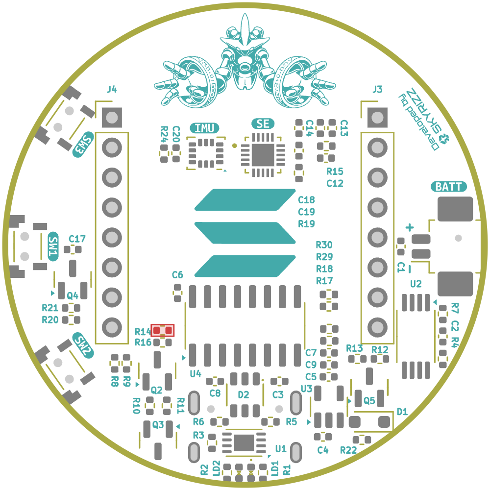 | 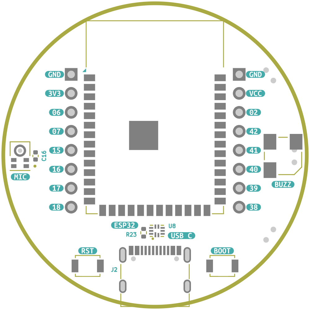 |
The ESPSOL DevKit is built around the ESP32-S3-WROOM-1-N16R8 module. It exposes 12 GPIO on two 8-pin 2.54 mm through-hole headers and integrates the peripherals needed for connected, secure, audio-capable applications without external wiring.
| MCU module | ESP32-S3-WROOM-1-N16R8 (Xtensa dual-core LX7, Wi-Fi 802.11 b/g/n 2.4 GHz, Bluetooth LE 5) |
| Flash / PSRAM | 16 MB flash, 8 MB PSRAM (octal) |
| Secure element | NXP EdgeLock SE050 (I²C) |
| IMU | ST LSM6DS3 3-axis accelerometer + 3-axis gyroscope (I²C) |
| Microphone | Knowles SPH0641LM4H-1 PDM MEMS microphone |
| Audio out | Magnetic buzzer (KSSG33J12-3), transistor-driven |
| USB | USB-C (USB 2.0) with on-board HID / UART switcher — native USB (HID / USB-Serial-JTAG) or CH340C USB-UART, selected by GPIO13 |
| Power | USB-C 5 V or single-cell Li-Po; on-board charger + protection + power path |
| Board | Ø 40.64 mm (1.6") circular, 2-layer FR-4 |
Two 8-pin headers break out power and 12 GPIO. Pin 1 is the square pad on each header. Silkscreen labels are shown on the bottom side of the board.
| Pin | Silk | Signal | ESP32-S3 | Notes |
|---|---|---|---|---|
| 1 | GND | GND | — | Ground |
| 2 | VCC | VSYS | — | System rail (battery / USB, unregulated) |
| 3 | 02 | GPIO2 | IO2 | General purpose |
| 4 | 42 | GPIO42 | IO42 | General purpose |
| 5 | 41 | GPIO41 | IO41 | General purpose |
| 6 | 40 | GPIO40 | IO40 | General purpose |
| 7 | 39 | GPIO39 | IO39 | General purpose |
| 8 | 38 | GPIO38 | IO38 | General purpose |
| Pin | Silk | Signal | ESP32-S3 | Notes |
|---|---|---|---|---|
| 1 | GND | GND | — | Ground |
| 2 | 3V3 | 3V3 | — | Regulated 3.3 V (from on-board LDO) |
| 3 | 06 | GPIO6 | IO6 | General purpose |
| 4 | 07 | GPIO7 | IO7 | General purpose |
| 5 | 15 | GPIO15 | IO15 | General purpose |
| 6 | 16 | GPIO16 | IO16 | General purpose |
| 7 | 17 | GPIO17 | IO17 | General purpose |
| 8 | 18 | GPIO18 | IO18 | General purpose |
Power note:
VCC/VSYS follows the battery/USB input voltage and is not regulated. Use the3V3pin for logic-level supply.
These GPIO are dedicated to on-board devices and are not available on the headers.
| ESP32-S3 | Function | Connected to |
|---|---|---|
| GPIO9 | I²C SCL | LSM6DS3 IMU + SE050 secure element |
| GPIO10 | I²C SDA | LSM6DS3 IMU + SE050 secure element |
| GPIO4 | IMU interrupt | LSM6DS3 INT1 |
| GPIO5 | Secure-element reset | SE050 reset |
| GPIO11 | PDM mic data | SPH0641LM4H-1 |
| GPIO12 | PDM mic clock | SPH0641LM4H-1 |
| GPIO48 | Buzzer | SS8050 driver → KSSG33J12-3 |
| GPIO3 | Battery voltage sense (ADC1) | VSYS via 22 k/22 k divider (½ scale) |
| GPIO13 | HID / UART switcher select | FSUSB42 mux — native USB (HID) ⇄ CH340 UART |
| GPIO43 | UART0 TX | CH340C |
| GPIO44 | UART0 RX | CH340C |
| GPIO19 | USB D+ | Native USB (via mux → USB-C) |
| GPIO20 | USB D− | Native USB (via mux → USB-C) |
GPIO35–37 are used internally by the octal PSRAM and are unavailable. GPIO8, GPIO14, GPIO45, and GPIO46 exist on the module but are not routed to the headers on this revision.
| Control | Signal | Function |
|---|---|---|
RST | EN | Reset the ESP32-S3 |
BOOT | GPIO0 | Boot / download mode (hold during reset) |
SW1 | GPIO47 | User button |
SW2 | GPIO21 | User button |
SW3 | GPIO1 | User button |
Two indicator LEDs — LD1 (red) and LD2 (blue) — are driven by the charger's
STAT output and show battery charge status (charging / charge complete). They are
not connected to a GPIO.
The USB-C connector (J2) is routed to one of two targets through an FSUSB42 2:1 USB switch (U8). GPIO13 selects which endpoint owns the data lines:
                                   ┌─ Port 1 (HSD1) ─ R29/R30 ─ ESP32-S3 native USB (HID / JTAG)
USB-C (J2) ─ SRV05-4 ESD ─ FSUSB42 ┤
                              ▲    └─ Port 2 (HSD2) ───────────── CH340C  ─ UART0 (GPIO43/44)
                              │
                          SEL = GPIO13
USB data lines are protected by an SRV05-4 TVS/ESD array (D2).
| Stage | Part | Function |
|---|---|---|
| Input | USB-C (5 V) / Li-Po via J1 | Dual power source |
| Battery connector | J1 — MX1.25 2-pin (BATT) | Single-cell Li-Po |
| Charger | MCP73831 | Single-cell Li-Po linear charger |
| Battery protection | DW03D | Over-charge / over-discharge / short-circuit |
| Power path | AO3401A P-MOSFET | Auto-select USB vs battery → VSYS |
| Regulator | ME6211C33M5 | 500 mA LDO, VSYS → 3.3 V |
| Reverse/steering | BAT60A Schottky | Power-path steering |
VSYS is available on J4 pin 2 and regulated 3V3 on J3 pin 2.
The system/battery rail can be read on GPIO3 (ADC1) through a 22 k/22 k
divider — actual voltage ≈ ADC_reading × 2.
All fixed peripherals hang off the pins below. Examples use the Arduino-ESP32 / ESP-IDF pin names; adapt to your framework.
Both the IMU and the secure element share one I²C bus:
Wire.begin(/*SDA=*/10, /*SCL=*/9); // GPIO10 = SDA, GPIO9 = SCL| Device | 7-bit address | Reset | Notes |
|---|---|---|---|
| LSM6DS3 (IMU) | 0x6A | — | SA0 tied low, CS tied high → I²C mode |
| SE050 (secure element) | 0x48 | GPIO5 | Pulse GPIO5 low to reset before init |
0x6A (GPIO9/10).INT1). Configure it as an input and
attach an ISR for wake-on-motion / tap / free-fall events.0x48 (GPIO9/10).i2s_pdm_rx).ledcAttach(48, 2700 /*Hz*/, 8); // ~2.7 kHz is near the buzzer's resonance
ledcWrite(48, 128); // 50% duty = beep; 0 = silentSTAT pin — no GPIO needed.Each button connects its GPIO to GND, so enable the internal pull-up and read active-low:
pinMode(47, INPUT_PULLUP);   // SW1
pinMode(21, INPUT_PULLUP);   // SW2
pinMode(1, INPUT_PULLUP); // SW3| Button | GPIO | Typical use |
|---|---|---|
| SW1 | 47 | User input / confirm |
| SW2 | 21 | User input |
| SW3 | 1 | User input |
| BOOT | 0 | Download mode (hold at reset); usable as a button in the app |
| RST | EN | Hardware reset |
Set GPIO13 to choose what the USB-C port presents (see USB — HID / UART switcher):
pinMode(13, OUTPUT);
digitalWrite(13, LOW);    // one setting → ESP32-S3 native USB (HID / USB-JTAG)
digitalWrite(13, HIGH);   // other setting → CH340C USB-UART bridge
The two states map to Port 1 (native USB) and Port 2 (CH340). Confirm the polarity on first bring-up and lock it into your firmware default.
The ESPSOL DevKit pairs a wireless MCU with a tamper-resistant secure element, user-confirmation buttons, and audio feedback — the exact ingredients for self-custody and on-chain device applications. The round form factor is designed to drop into wearables, fobs, and point-of-sale enclosures.
Example use cases:
The hardware provides the secure key custody, connectivity, and I/O; the Solana integration (RPC, transaction building, signing flow) lives in your firmware and companion app.
Interactive BOM: hardware/bom/ibom.html
| Ref | Part | Description |
|---|---|---|
| U5 | ESP32-S3-WROOM-1-N16R8 | Wi-Fi + BLE SoC module, 16 MB flash / 8 MB PSRAM |
| U6 | SE050C2HQ1 | NXP EdgeLock secure element (I²C) |
| U7 | LSM6DS3 | 6-axis IMU (accel + gyro) |
| U8 | FSUSB42UMX | 2:1 USB 2.0 switch — HID / UART switcher |
| U4 | CH340C | USB-to-UART bridge (crystal-less) |
| U1 | MCP73831 | Li-Po charge controller |
| U2 | DW03D | Battery protection IC |
| U3 | ME6211C33M5 | 3.3 V / 500 mA LDO |
| — | SPH0641LM4H-1 | PDM MEMS microphone |
| LS1 | KSSG33J12-3 | Magnetic buzzer |
| Q5 | AO3401A | P-channel MOSFET (power path) |
| Q2–Q4 | SS8050 | NPN transistors |
| D1 | BAT60A | Schottky diode |
| D2 | SRV05-4 | USB TVS/ESD protection array |
| LD1 / LD2 | LED (red / blue) | Charge-status indicators |
| J1 | MX1.25 2-pin | Li-Po battery connector |
| J2 | USB-C 2.0 (16P) | Power + data |
| J3 / J4 | 1×8 header, 2.54 mm | GPIO / power breakout |
| SW1–SW3, BOOT, RST | Tactile switches | User / boot / reset buttons |
hardware/                    KiCad project
  SkyRizzESPSOL.kicad_pro    Project
  SkyRizzESPSOL.kicad_sch    Schematic
  SkyRizzESPSOL.kicad_pcb    PCB layout
  bom/ibom.html              Interactive BOM
assets/                      Board renders
LICENSE.md CERN-OHL-S v2Hardware design files are released under the CERN Open Hardware Licence
Version 2 – Strongly Reciprocal (CERN-OHL-S v2). See LICENSE.md.
| Qty | Value | Footprint | References |
|---|---|---|---|
| 10 | 10K | Resistor_SMD:R_0402_1005Metric | R3, R8, R9, R10, R11, R15, R16, R19, R20, R24 |
| 8 | 100n | Capacitor_SMD:C_0402_1005Metric | C2, C8, C9, C13, C16, C18, C19, C20 |
| 4 | 1U | Capacitor_SMD:C_0402_1005Metric | C3, C6, C7, C12 |
| 3 | 10U | Capacitor_SMD:C_0402_1005Metric | C1, C4, C5 |
| 3 | 1K | Resistor_SMD:R_0402_1005Metric | R1, R2, R7 |
| 3 | SEL | NIP_MOD:SW_TS31-46-35-BK-B-160-RA-SMT-TR | SW1, SW2, SW3 |
| 3 | SS8050 | Package_TO_SOT_SMD:SOT-23 | Q2, Q3, Q4 |
| 2 | 100K | Resistor_SMD:R_0402_1005Metric | R22, R23 |
| 2 | 22 | Resistor_SMD:R_0402_1005Metric | R29, R30 |
| 2 | 22K | Resistor_SMD:R_0402_1005Metric | R12, R13 |
| 2 | 2K2 | Resistor_SMD:R_0402_1005Metric | R17, R18 |
| 2 | 2U2 | Capacitor_SMD:C_0402_1005Metric | C14, C17 |
| 2 | 5K1 | Resistor_SMD:R_0402_1005Metric | R5, R6 |
| 2 | Conn_01x08_Pin | Connector_PinHeader_2.54mm:PinHeader_1x08_P2.54mm_Vertical | J3, J4 |
| 2 | G*** | kibuzzard-6A47B7C8 | kibuzzard-6A47B7C8, kibuzzard-6A47B7C8 |
| 2 | SW_Push | Button_Switch_SMD:SW_SPST_B3U-1000P | BOOT1, RST1 |
| 1 | 100 | Resistor_SMD:R_0402_1005Metric | R4 |
| 1 | 220 | Resistor_SMD:R_0402_1005Metric | R14 |
| 1 | 470K | Resistor_SMD:R_0402_1005Metric | R21 |
| 1 | AO3401A | PCM_JLCPCB:Q_SOT-23 | Q5 |
| 1 | BAT60A | Diode_SMD:D_SOD-323_HandSoldering | D1 |
| 1 | CH340C | Package_SO:SOIC-16_3.9x9.9mm_P1.27mm | U4 |
| 1 | DW03D | Package_SO:TSSOP-8_4.4x3mm_P0.65mm | U2 |
| 1 | ESP32-S3-WROOM-1-N16R8 | RF_Module:ESP32-S3-WROOM-1 | U5 |
| 1 | FSUSB42UMX | NIP_MOD:IC_FSUSB42UMX | U8 |
| 1 | G*** | kibuzzard-6A484E77 | kibuzzard-6A484E77 |
| 1 | G*** | kibuzzard-6A484D43 | kibuzzard-6A484D43 |
| 1 | G*** | kibuzzard-6A484D4D | kibuzzard-6A484D4D |
| 1 | G*** | kibuzzard-6A47B6AB | kibuzzard-6A47B6AB |
| 1 | G*** | kibuzzard-6A484D52 | kibuzzard-6A484D52 |
| 1 | G*** | kibuzzard-6A48566E | kibuzzard-6A48566E |
| 1 | G*** | kibuzzard-6A47B6EC | kibuzzard-6A47B6EC |
| 1 | G*** | kibuzzard-6A47B67E | kibuzzard-6A47B67E |
| 1 | G*** | kibuzzard-6A47BCEB | kibuzzard-6A47BCEB |
| 1 | G*** | kibuzzard-6A484D48 | kibuzzard-6A484D48 |
| 1 | G*** | kibuzzard-6A47B6E1 | kibuzzard-6A47B6E1 |
| 1 | G*** | kibuzzard-6A485201 | kibuzzard-6A485201 |
| 1 | G*** | kibuzzard-6A47BD0F | kibuzzard-6A47BD0F |
| 1 | G*** | kibuzzard-6A484D3D | kibuzzard-6A484D3D |
| 1 | G*** | kibuzzard-6A484D35 | kibuzzard-6A484D35 |
| 1 | G*** | kibuzzard-6A484E6E | kibuzzard-6A484E6E |
| 1 | G*** | kibuzzard-6A47B7CE | kibuzzard-6A47B7CE |
| 1 | G*** | kibuzzard-6A47BCCB | kibuzzard-6A47BCCB |
| 1 | G*** | kibuzzard-6A484E69 | kibuzzard-6A484E69 |
| 1 | G*** | kibuzzard-6A47BCB8 | kibuzzard-6A47BCB8 |
| 1 | G*** | kibuzzard-6A484E7B | kibuzzard-6A484E7B |
| 1 | G*** | kibuzzard-6A47D016 | kibuzzard-6A47D016 |
| 1 | G*** | kibuzzard-6A484E64 | kibuzzard-6A484E64 |
| 1 | G*** | kibuzzard-6A47B661 | kibuzzard-6A47B661 |
| 1 | G*** | kibuzzard-6A484E72 | kibuzzard-6A484E72 |
| 1 | G*** | kibuzzard-6A47B686 | kibuzzard-6A47B686 |
| 1 | LED BLUE | LED_SMD:LED_0402_1005Metric | LD2 |
| 1 | LED RED | LED_SMD:LED_0402_1005Metric | LD1 |
| 1 | LOGO | NIP_LOGO:S_LOGO_10 | G*** |
| 1 | LOGO | NIP_LOGO:alakazam | G*** |
| 1 | LOGO | NIP_LOGO:dev_skyrizz_2 | G*** |
| 1 | LSM6DS3 | Package_LGA:LGA-14_3x2.5mm_P0.5mm_LayoutBorder3x4y | U7 |
| 1 | MCP73831-2-MC | Package_DFN_QFN:DFN-8-1EP_3x2mm_P0.5mm_EP1.7x1.4mm | U1 |
| 1 | ME6211C33M5 | Package_TO_SOT_SMD:SOT-23-5 | U3 |
| 1 | MX1.25mm-2P | Connector_Molex:Molex_PicoBlade_53261-0271_1x02-1MP_P1.25mm_Horizontal | J1 |
| 1 | SE050C2HQ1_Z01SDZ | NIP_MOD:QFN40P300X300X33-21N | U6 |
| 1 | SPH0641LM4H-1 | NIP_MOD:MIC_SPH0641LM4H-1 | MK2 |
| 1 | SRV05-4-P-T7 | PCM_JLCPCB:SOT-23-6_L2.9-W1.6-P0.95-LS2.8-BR | D2 |
| 1 | USB_C_Receptacle_USB2.0_16P | Connector_USB:USB_C_Receptacle_G-Switch_GT-USB-7010ASV | J2 |
| 1 | YX-SMD5020 | NIP_MOD:XDCR_KSSG33J12-3 | LS1 |


OnionDAO-git/oniondao-badge
An open-source, hacker-conference-style electronic badge built around the ESP32-S3-WROOM-1-N8R8 (8 MB flash + 8 MB Octal PSRAM), with swappable RF / audio / storage modules, an e-paper (or TFT) display socket, a secure…

JoeMighty/opentouch-s3
A modern remake of the Bare Conductive Touch Board: 12 capacitive touch electrodes, MP3/WAV/MIDI audio, and now WiFi, Bluetooth LE, USB-C, a proper LiPo power path, a fuel gauge, line-in, MIDI out, Qwiic and an RGB LED.


olerast67/emotion-keychain
Брелок с OLED-экраном и анимированными эмоциями

zgeez/Pixel-Badge
Wearable 32x32 LED badge with Zephyr firmware, BLE control, passive NFC, and a Flutter Android app, built around a custom nRF52840 PCB.
101 parts, built around the CH340C, ESP32-S3-WROOM-1-N16R8, DW03D and FSUSB42UMX. The full list of its parts is on this page, with links to each part's symbol and footprint where PCBKit's library has them.
From the SkyRizzAI/SkyRizz-ESPSOL repository on GitHub, at the commit this page was made from: the board is hardware/SkyRizzESPSOL.kicad_pcb and its schematic hardware/SkyRizzESPSOL.kicad_sch. PCBKit opens the board in the browser, with nothing to install.
Its repository publishes it under the CERN-OHL-S-2.0 licence: you may reuse it on that licence's terms (keep the author's notice, and for a copyleft licence share your changes alike).