4 layers51 × 77 mm

 SingularTeabag/Battery-Management
A Repository for Battery Management PCBs
Battery Management is an open-source printed circuit board by SingularTeabag, from the SingularTeabag/Battery-Management repository on GitHub, published under the GPL-3.0 licence. It is a 2-layer board of 32.3 × 11.5 mm with 34 parts on 21 nets, routed with 160 tracks and 22 vias.
It is built around the BQ25185DLHR and MAX17048G+T10. Its parts include 14 connectors, 9 resistors, 7 capacitors, 3 ICs and 1 inductor. It belongs with the power boards of this library.


A repository to organize my battery management PCBs
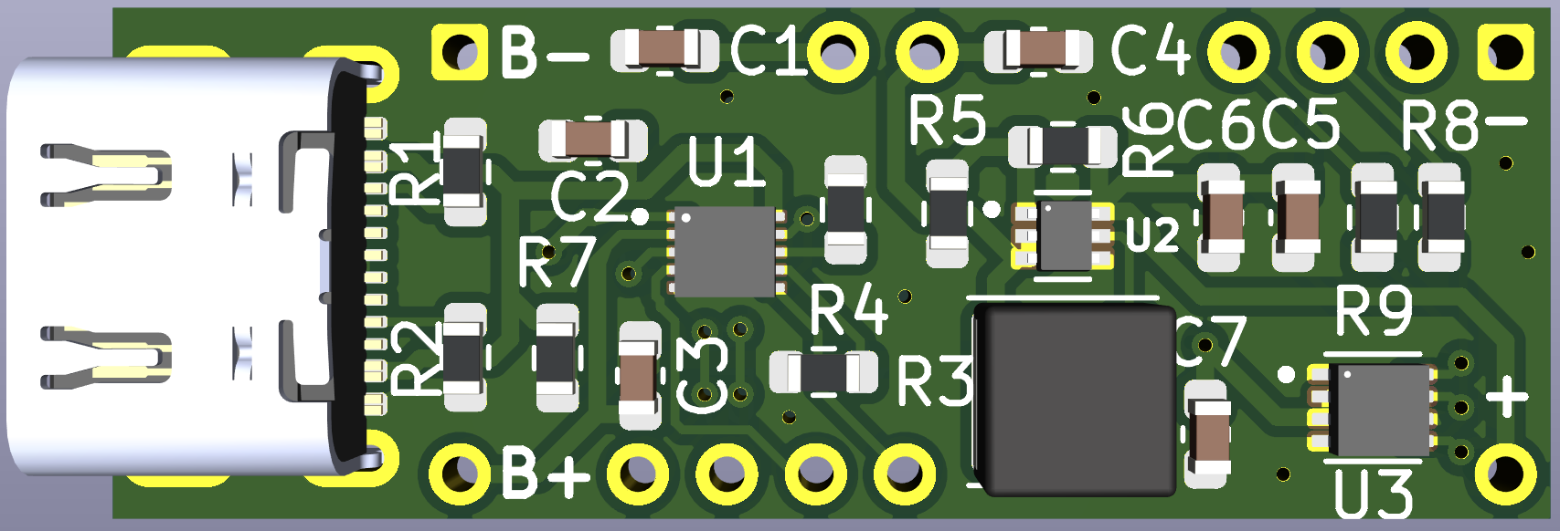
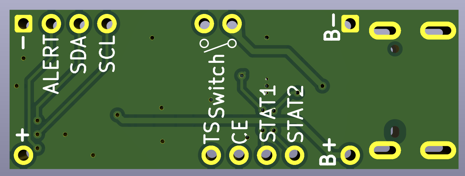
This PCB is my first "real" PCB that I've designed from scratch using the datasheets of the three respective chips. That aside this PCB is intended for easy battery support for prototyping with microcontroller development boards that require a stable 5 volt input. The board breaks out STAT1, STAT2, CE, and TS from BQ25185DLHR to allow data and control to the used microcontroller, and an external thermistor for battery safety. The board additionally has two pins meant to be used for an external on/off switch, marked on the back silkscreen. Like the battery charging IC the fuel gauges' data signals are also broken out to intended for use with the microcontroller. The USB type C port does not have it's data plus and data minus pins broken out, these are used as a differential pair which requires both wires to be exactly the same length and require impedance matching which all goes out the window when using external wires.
| Qty | Value | Footprint | References |
|---|---|---|---|
| 11 | Conn_01x01_Pin | Custom Footprints:Connector Hole | J1, J3, J5, J6, J7, J8, J9, J10, J11, J12, J13 |
| 2 | 10uF | Capacitor_SMD:C_0603_1608Metric | C1, C4 |
| 2 | 1uF | Capacitor_SMD:C_0603_1608Metric | C2, C3 |
| 2 | 22uF | Capacitor_SMD:C_0603_1608Metric | C5, C6 |
| 2 | 4.7K | Resistor_SMD:R_0603_1608Metric | R8, R9 |
| 2 | 5.1K | Resistor_SMD:R_0603_1608Metric | R1, R2 |
| 2 | Conn_01x01_Pin | Custom Footprints:Ground Hole | J2, J4 |
| 1 | 0.1uF | Capacitor_SMD:C_0603_1608Metric | C7 |
| 1 | 100K | Resistor_SMD:R_0603_1608Metric | R5 |
| 1 | 10K | Resistor_SMD:R_0603_1608Metric | R7 |
| 1 | 1K | Resistor_SMD:R_0603_1608Metric | R4 |
| 1 | 1uH | Inductor_SMD:L_APV_ANR4030 | L1 |
| 1 | 5K | Resistor_SMD:R_0603_1608Metric | R3 |
| 1 | 732K | Resistor_SMD:R_0603_1608Metric | R6 |
| 1 | BQ25185DLHR | BQ25185DLHR:IC_BQ25185DLHR | U1 |
| 1 | MAX17048G | MAX17048G_:SON50P200X200X80-9N | U3 |
| 1 | TPS61023DRLT | TPS61023DRLT:SOT50P160X60-6N | U2 |
| 1 | USB_C_Plug_USB2.0 | Connector_USB:USB_C_Receptacle_JAE_DX07S016JA1R1500 | P1 |

jfwoods/insta360link-controller
A lightweight daemon, CLI tool, and (optional) firmware + hardware for controlling an Insta360 Link webcam without the first-party software.


Avinash1286/pendent
AURA: open wearable note-taking device development — PCB, printable case, firmware, Next.js/Convex notes, interactive 3D site and launch film.


balu-16/SeedGrant_Safety
Personal-safety project: Expo / React Native client + FastAPI + PostgreSQL (Supabase) backend + React admin portal.

CDonohoe-Designs/EdgeLink_S3_Cellular
EdgeLink S3 Cellular is a four-layer embedded hardware platform combining an ESP32-S3 controller, SIM7080G cellular/GNSS modem, USB-C, battery power management and environmental/motion sensing.

It measures 32.3 × 11.5 mm and has 2 copper layers, 1.6 mm thick.
34 parts, built around the BQ25185DLHR and MAX17048G+T10. The full list of its parts is on this page, with links to each part's symbol and footprint where PCBKit's library has them.
From the SingularTeabag/Battery-Management repository on GitHub, at the commit this page was made from: the board is Single Cell 5 Volt Regulated/Battery Management.kicad_pcb and its schematic Single Cell 5 Volt Regulated/Battery Management.kicad_sch. PCBKit opens the board in the browser, with nothing to install.
Its repository publishes it under the GPL-3.0 licence: you may reuse it on that licence's terms (keep the author's notice, and for a copyleft licence share your changes alike).