2 layers75 × 50 mm

 SharKingStudios/carkit4
An all in one PCB for controlling DIY RC Cars!
Carkit PANEL is an open-source printed circuit board by SharKingStudios, from the SharKingStudios/carkit repository on GitHub, published under the MIT licence. It is a 2-layer board of 75 × 102 mm with 126 parts on 62 nets, routed with 912 tracks and 98 vias.
It is built around the ESP32-C3-MINI-1, AMS1117-3.3 and SK6812, with the CYA1040-33UH, RVT1E331M0810 and RVT1H470M0607 among its other parts. Its parts include 38 capacitors, 20 resistors, 14 connectors, 12 diodes and 10 ICs. It belongs with the ESP32 and RISC-V boards of this library.


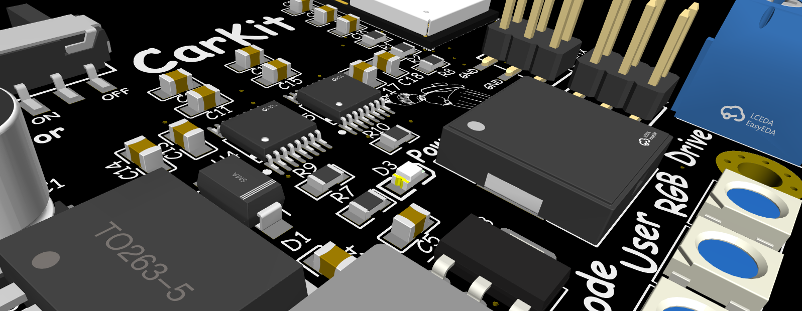
(You bring the chassis. It brings the brains.)
Visuals because everyone loves eye candy.
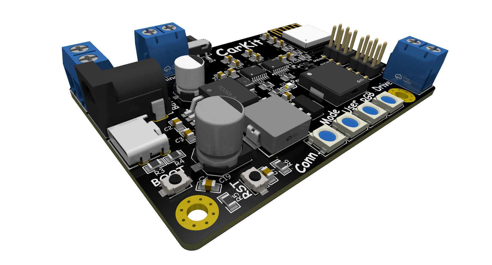
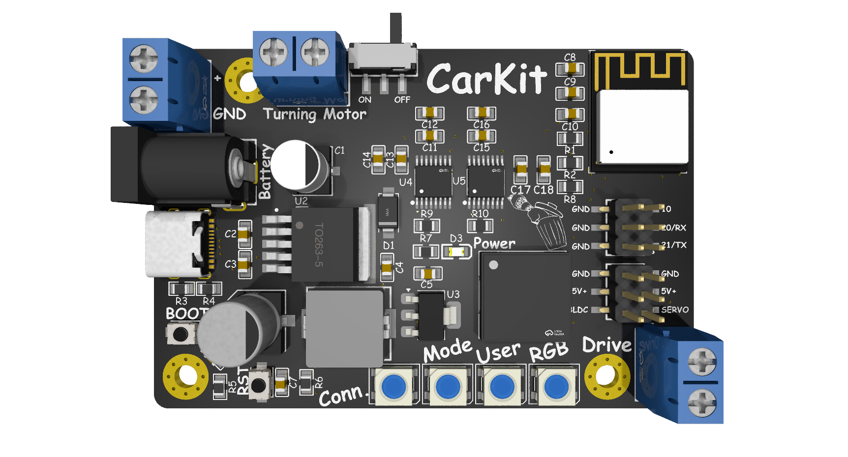
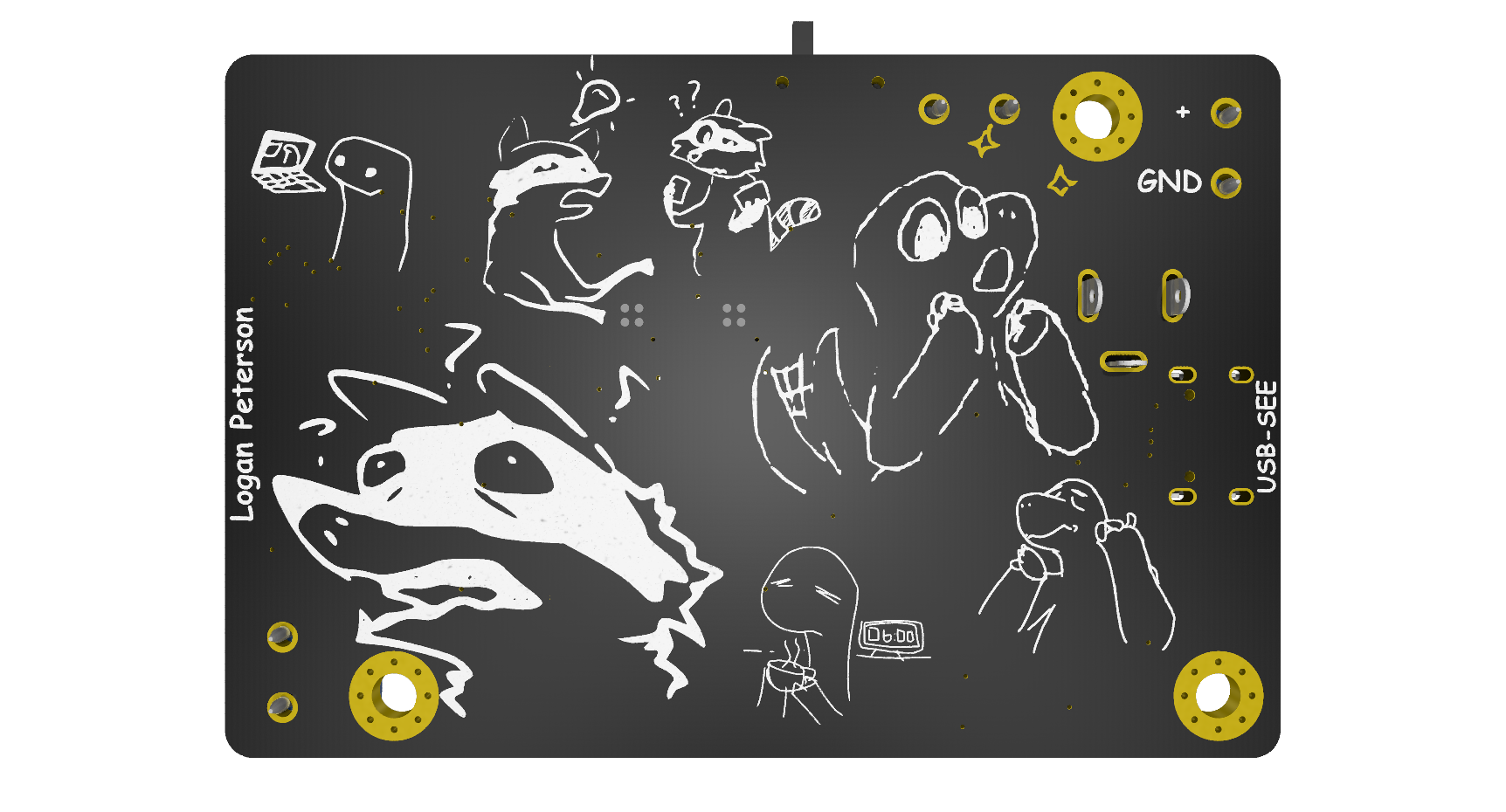
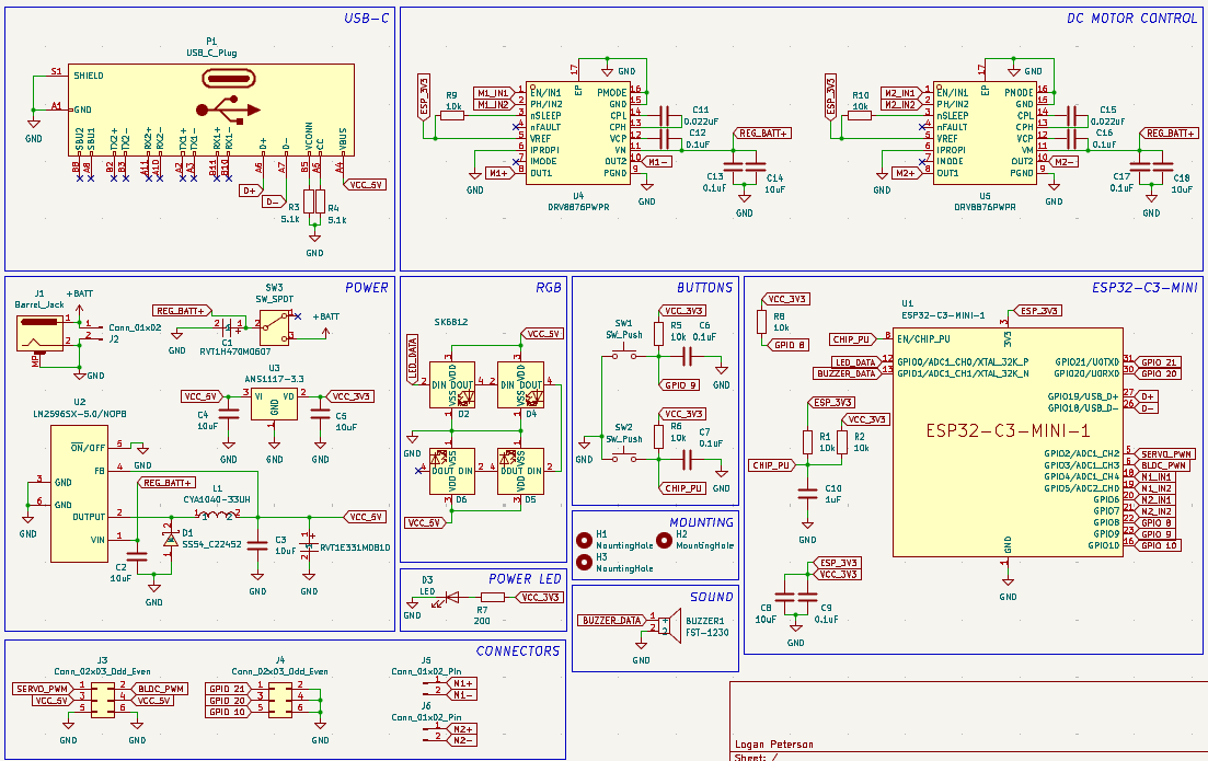
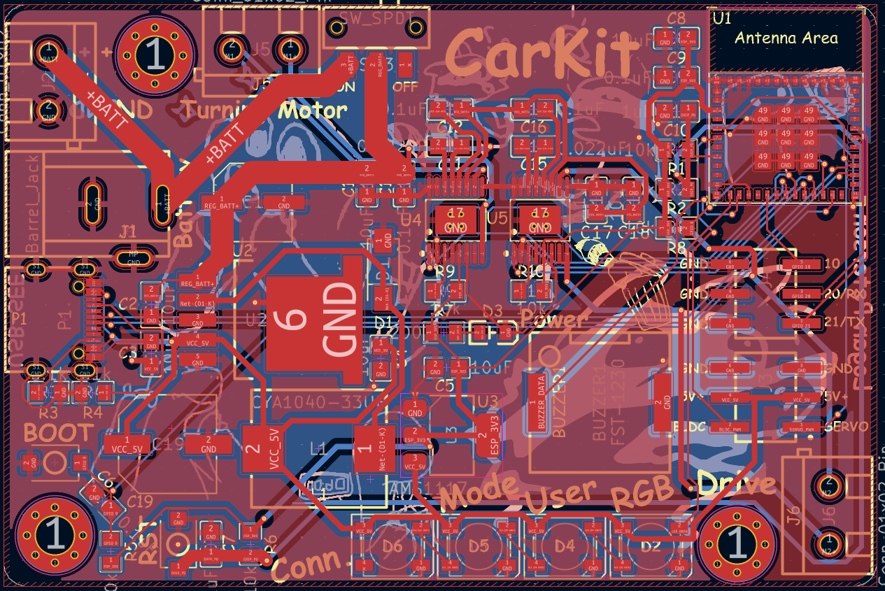
All the silicon, blinkenlights, and screw-down bits live here.
Main characters:
(See BOM.md for the full part list, values, and LCSC links.)
This is a do-it-all RC control board built around an ESP32-C3, designed to handle basically everything you might want on a DIY RC car:
It’s meant to be the drop-in brain for “I duct-taped this together but now I want it to drive nicely” RC builds.
*While the board supports tank drive it wasn't built for it.
Because every DIY RC build uses a different battery, obviously.
(Dont feed the board anything over 36V, I would recommend staying under 24V)
| Channel | Type | Typical Use | Notes |
|---|---|---|---|
| M1 | DC Motor | Main Drive | PWM + DIR via DRV8876 |
| M2 | DC Motor | Turning / Steering | PWM + DIR via DRV8876 |
| BLDC OUT | PWM Signal | Brushless ESC Input | External ESC drives the BLDC motor |
| SERVO OUT | Servo PWM | Steering / Gimbal / Etc. | Standard RC-style servo signal |
At a high level:
All the “annoying parts” (power, drivers, IO protection, connectors, etc.) are on the PCB, so you can focus on mechanical design.
The exact firmware and controller mapping is up to you and some basic stuff is included, but the general idea is:
(You can map “A” to beep the buzzer. You absolutely should.)
Because a control board without RGB is just morally wrong.
Possible roles for the 4 SK6812 LEDs:
Or ignore all that and just run full rainbow vomit. No judgment.
This board exists for that moment when you’ve got:
It’s meant to be the one board that handles:
…so you can just design something cool and let this handle the boring electronics.
Have ideas? Want a new connector, mode, sample firmware, or just want to roast my layout?
This project is open-source, powered by vibes, and tested mostly on my own questionable hardware.
If you:
…and it smokes, explodes, or develops sentience, that’s entirely on you.
Happy hacking!
| Qty | Value | Footprint | References |
|---|---|---|---|
| 16 | LOGO | LOGO | G***, G***, G***, G***, G***, G***, G***, G***, G***1, G***2, G***3, G***4, G***5, G***6, G***7, G***8 |
| 14 | 0.1uF | imported_components:C0805 | C6, C7, C9, C12, C13, C16, C17, C25, C26, C28, C31, C32, C35, C36 |
| 14 | 10k | imported_components:R0805 | R1, R2, R5, R6, R8, R9, R10, R11, R12, R15, R16, R18, R19, R20 |
| 14 | 10uF | imported_components:C0805 | C2, C3, C4, C5, C8, C14, C18, C21, C22, C23, C24, C27, C33, C37 |
| 8 | SK6812 | LED_SMD:LED_SK6812_PLCC4_5.0x5.0mm_P3.2mm | D2, D4, D5, D6, D8, D10, D11, D12 |
| 6 | MountingHole | MountingHole:MountingHole_3.2mm_M3_Pad_Via | H1, H2, H3, H4, H5, H6 |
| 4 | 0.022uF | imported_components:C0805 | C11, C15, C30, C34 |
| 4 | 5.1k | imported_components:R0805 | R3, R4, R13, R14 |
| 4 | Conn_01x02_Pin | imported_components:CONN-TH_P5.00_KF301-5.0-2P | J5, J6, J11, J12 |
| 4 | Conn_02x03_Odd_Even | imported_components:HDR-SMD_6P-P2.54-V | J3, J4, J9, J10 |
| 4 | DRV8876PWPR | imported_components:HTSSOP-16_L5.0-W4.4-P0.65-LS6.4-BL-EP | U4, U5, U9, U10 |
| 4 | SW_Push | imported_components:SW-SMD_L3.9-W3.0-P4.45 | SW1, SW2, SW4, SW5 |
| 2 | 1uF | imported_components:C0805 | C10, C29 |
| 2 | 200 | imported_components:R0805 | R7, R17 |
| 2 | AMS1117-3.3 | Package_TO_SOT_SMD:SOT-223-3_TabPin2 | U3, U8 |
| 2 | Barrel_Jack | imported_components:DC-IN-TH_DC-005-A200 | J1, J7 |
| 2 | CYA1040-33UH | imported_components:IND-SMD_L11.6-W10.1 | L1, L2 |
| 2 | Conn_01x02 | imported_components:CONN-TH_P5.00_KF301-5.0-2P | J2, J8 |
| 2 | ESP32-C3-MINI-1 | PCM_Espressif:ESP32-C3-MINI-1 | U1, U6 |
| 2 | FST-1230 | imported_components:BUZ-SMD_L12.0-W12.0_FUET-1230 | BUZZER1, BUZZER2 |
| 2 | LED | imported_components:LED0805-RD | D3, D9 |
| 2 | LM2596SX-5.0/NOPB | imported_components:TO-263-5_L10.2-W8.9-P1.70-TL | U2, U7 |
| 2 | RVT1E331M0810 | imported_components:CAP-SMD_BD8.0-L8.3-W8.3-LS9.3-FD-1 | C19, C38 |
| 2 | RVT1H470M0607 | imported_components:CAP-SMD_BD6.3-L6.6-W6.6-LS7.6-FD | C1, C20 |
| 2 | SS54_C22452 | imported_components:SMA_L4.4-W2.8-LS5.4-R-RD | D1, D7 |
| 2 | SW_SPDT | imported_components:SW-SMD_MST-12D18G4-SPDT-SLIDE-SWITCH | SW3, SW6 |
| 2 | USB_C_Plug | imported_components:USB-C_SMD-TYPE-C-31-M-12 | P1, P2 |


SharKingStudios/Fracture
An infinitely expandable, velocity sensing split midi keyboard.

MycroftAI/hardware-mycroft-mark-II
Mycroft's Mark II Rpi mechanical, electrical and industrial designs


amuzdgp3-prog/im-01-pulse-device
Отдельный модуль к системе обслуживания аппаратов 2.apixspb.ru. Устройство слушает импульсные выходы монетоприёмника и купюроприёмника, копит показания в FRAM и дважды в сутки передаёт их на сервер по LTE Cat.1.


SharKingStudios/Santas-Microfactory
A factory game built entirely out of diode transistor logic.

gcormier/esphome-pressure
esphome board with a differential pressure sensor, supporting a variety of power sources
It measures 75 × 102 mm and has 2 copper layers, 1.6 mm thick.
126 parts, built around the ESP32-C3-MINI-1, AMS1117-3.3, SK6812 and CYA1040-33UH. The full list of its parts is on this page, with links to each part's symbol and footprint where PCBKit's library has them.
From the SharKingStudios/carkit repository on GitHub, at the commit this page was made from: the board is PCB/Panelized/carkit PANEL.kicad_pcb and its schematic PCB/carkit.kicad_sch. PCBKit opens the board in the browser, with nothing to install.
Its repository publishes it under the MIT licence: you may reuse it on that licence's terms (keep the author's notice, and for a copyleft licence share your changes alike).