2 layers15.7 × 20.8 mm
DAC7678 16TSSOP
dfieschko/Breakouts
A repository for breakout boards designed with KiCAD.
5 parts4GPL-3.0

 SengerM/UZH_4DPixChip_test_setup
Files related to the test setup for the 4D pixel chip prototype, PCB design
UZH 4DPixChip test setup is an open-source printed circuit board by SengerM, from the SengerM/UZH_4DPixChip_test_setup repository on GitHub. It is a 2-layer board of 121.7 × 88.4 mm with 62 parts on 273 nets, routed with 821 tracks and 116 vias.
It is built around the DAC7678SPW, SN74AVC2T45DCTT and LT3045EMSE-1#PBF. Its parts include 18 capacitors, 14 resistors, 14 ICs, 9 connectors and 1 diode.


This repo contains the files for the production of the PCBs for testing the analog front end for the 4D pixel readout chip prototype.
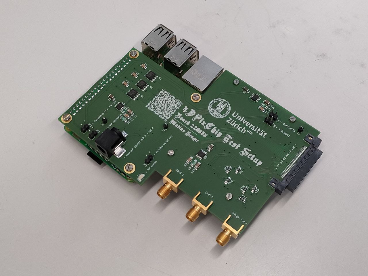
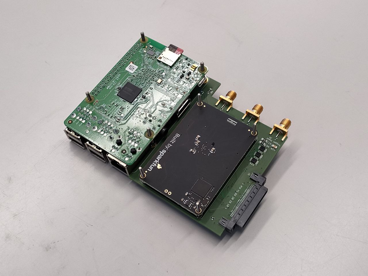
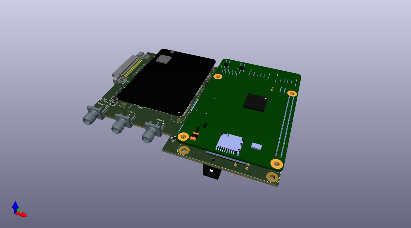
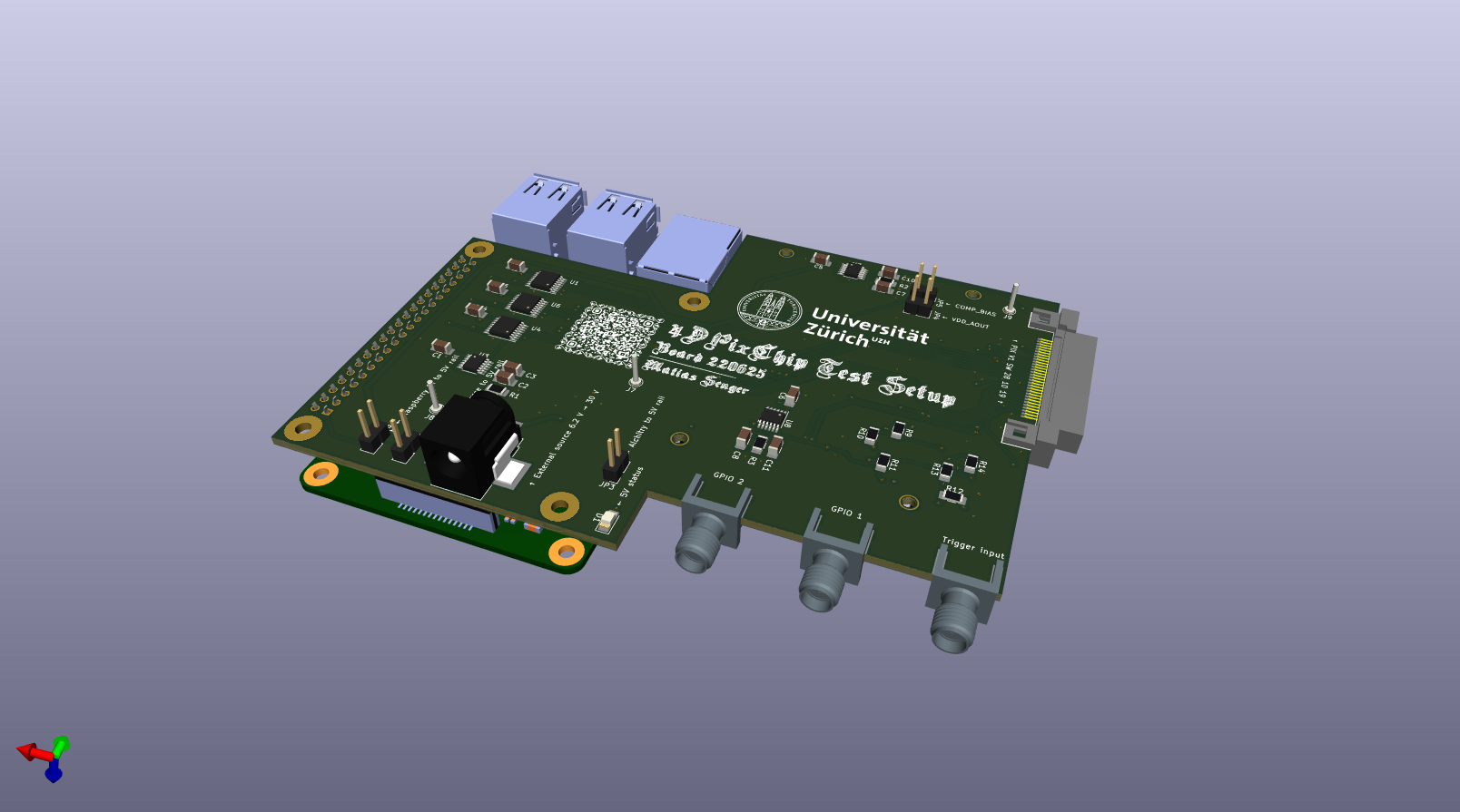
| Qty | Value | Footprint | References |
|---|---|---|---|
| 9 | 10k | Resistor_SMD:R_1206_3216Metric_Pad1.30x1.75mm_HandSolder | R4, R5, R6, R9, R10, R11, R12, R13, R14 |
| 6 | 100n | Capacitor_SMD:C_1206_3216Metric_Pad1.33x1.80mm_HandSolder | C2, C7, C8, C13, C16, C17 |
| 6 | SN74AVC2T45DCTT | Package_SO:MSOP-8_3x3mm_P0.65mm | U5, U10, U11, U12, U13, U14 |
| 5 | 10µ | Capacitor_SMD:C_1206_3216Metric_Pad1.33x1.80mm_HandSolder | C3, C9, C10, C11, C12 |
| 3 | 12k | Resistor_SMD:R_1206_3216Metric_Pad1.30x1.75mm_HandSolder | R1, R2, R3 |
| 3 | 1µ | Capacitor_SMD:C_1206_3216Metric_Pad1.33x1.80mm_HandSolder | C4, C14, C15 |
| 3 | 4.7µ | Capacitor_SMD:C_1206_3216Metric_Pad1.33x1.80mm_HandSolder | C1, C5, C6 |
| 3 | DAC7678SPW | Package_SO:TSSOP-16_4.4x5mm_P0.65mm | U1, U4, U6 |
| 3 | GND | Connector_Pin:Pin_D1.0mm_L10.0mm | J7, J8, J9 |
| 3 | LT3045EMSE-1#PBF | Package_SO:MSOP-12-1EP_3x4mm_P0.65mm_EP1.65x2.85mm | U3, U7, U8 |
| 1 | 100 | Resistor_SMD:R_1206_3216Metric_Pad1.30x1.75mm_HandSolder | R7 |
| 1 | 140 | Resistor_SMD:R_1206_3216Metric_Pad1.30x1.75mm_HandSolder | R8 |
| 1 | 1n | Capacitor_SMD:C_1206_3216Metric_Pad1.33x1.80mm_HandSolder | C18 |
| 1 | 5V status | LED_SMD:LED_1206_3216Metric_Pad1.42x1.75mm_HandSolder | D1 |
| 1 | Alchitry_Cu | Alchitry:Alchitry_Cu | U2 |
| 1 | Alchitry_to_5V_rail? | Connector_PinHeader_2.54mm:PinHeader_1x02_P2.54mm_Vertical | JP3 |
| 1 | COMP_BIAS | Connector_PinHeader_2.54mm:PinHeader_1x02_P2.54mm_Vertical | JP5 |
| 1 | External power source | Connector_BarrelJack:BarrelJack_CUI_PJ-036AH-SMT_Horizontal | J2 |
| 1 | External_source_to_5V_rail? | Connector_PinHeader_2.54mm:PinHeader_1x02_P2.54mm_Vertical | JP2 |
| 1 | GPIO 1 | UZH_4DPixChip_test_setup:SMA_EdgeMount | J5 |
| 1 | GPIO 2 | UZH_4DPixChip_test_setup:SMA_EdgeMount | J6 |
| 1 | LD1086DT50TR | Package_TO_SOT_SMD:TO-252-2 | U9 |
| 1 | LOGO | UZH_4DPixChip_test_setup:graphics | G*** |
| 1 | PIX V1 SW 28 10 19 | UZH_4DPixChip_test_setup:SAMTEC_HSEC8-130-01-L-D-EM2 | J3 |
| 1 | Raspberry_Pi_2_3 | Raspberry_Pi:MODULE_RASPBERRY_PI_3_MODEL_B+ | J1 |
| 1 | Raspberry_Pi_to_5V_rail? | Connector_PinHeader_2.54mm:PinHeader_1x02_P2.54mm_Vertical | JP1 |
| 1 | Trigger input | UZH_4DPixChip_test_setup:SMA_EdgeMount | J4 |
| 1 | VDD_AOUT | Connector_PinHeader_2.54mm:PinHeader_1x02_P2.54mm_Vertical | JP4 |
dfieschko/Breakouts
A repository for breakout boards designed with KiCAD.

lever-tech/flake
An open-source, wireless, split ergonomic keyboard designed to be productive, healthy, and enjoyable. [formerly Anywhy Flake]

imchipwood/dumbpad
Simple 4x4 numpad with rotary encoder. Powered by QMK via ATmega32u4 Pro Micro

hydrabus/hydrabus
HydraBus open source multi-tool for anyone interested in learning/developping/debugging/hacking/Penetration Testing for basic or advanced embedded hardware

im-tomu/fomu-hardware
Tomu FPGA (Fomu for short), a FPGA which fits inside your USB port!


It measures 121.7 × 88.4 mm and has 2 copper layers, 1.6 mm thick.
62 parts, built around the DAC7678SPW, SN74AVC2T45DCTT and LT3045EMSE-1#PBF. The full list of its parts is on this page, with links to each part's symbol and footprint where PCBKit's library has them.
From the SengerM/UZH_4DPixChip_test_setup repository on GitHub, at the commit this page was made from: the board is UZH_4DPixChip_test_setup.kicad_pcb and its schematic UZH_4DPixChip_test_setup.kicad_sch. PCBKit opens the board in the browser, with nothing to install.
Its repository states no licence, so its author keeps all rights: ask SengerM before reusing the design.