2 layers19 × 76 mm
Sub
google/mozc-devices
Circuit diagrams and firmware source code for Gboard DIY keyboards
15 parts3kApache-2.0

 SeanP2001/pico-handheld-games-console1
A handheld games console, based on the Raspberry Pi Pico.
Pico Handheld is an open-source printed circuit board by SeanP2001, from the SeanP2001/pico-handheld-games-console repository on GitHub, published under the GPL-3.0 licence. It is a 2-layer board of 86.4 × 91.4 mm with 15 parts on 45 nets, routed with 122 tracks and 4 vias.
Its parts include 7 switches, 3 ICs and 1 diode. It belongs with the RP2040 boards of this library.
I started this project to follow on from my ATtiny Handheld Games Console. I decided the project was not as accessible as I wanted because programming an ATtiny is not simple enough for a beginner. While the limitations of the ATtiny make it a fun challenge to create games, it would be nice to be able to make something more elaborate.
I wanted to make a USB-programmable games console which could be programmed using either MicroPython or C++ (Arduino). I also wanted to use silicone button membranes to give the buttons a more premium feel compared to the tactile buttons on the ATtiny console. I also decided to make a version with a colour LCD display (see the "LCD_Version" branch).
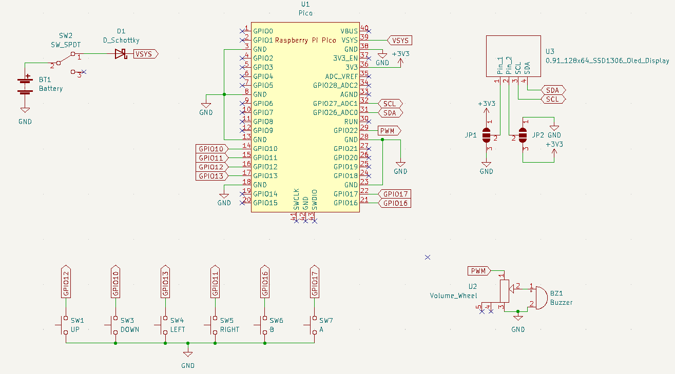
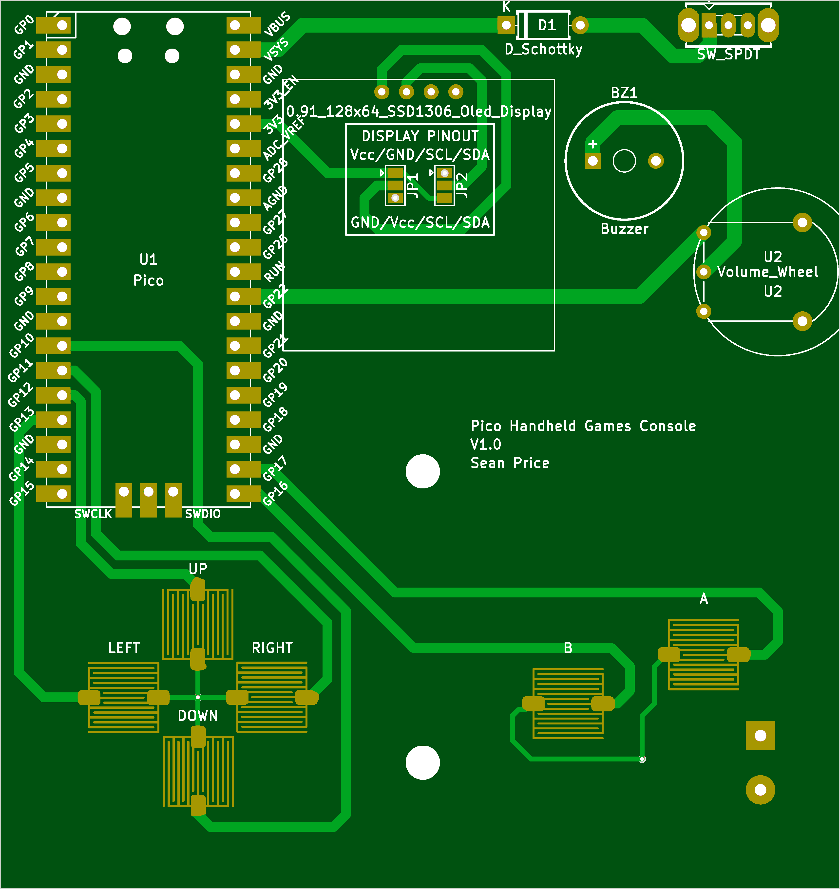 | 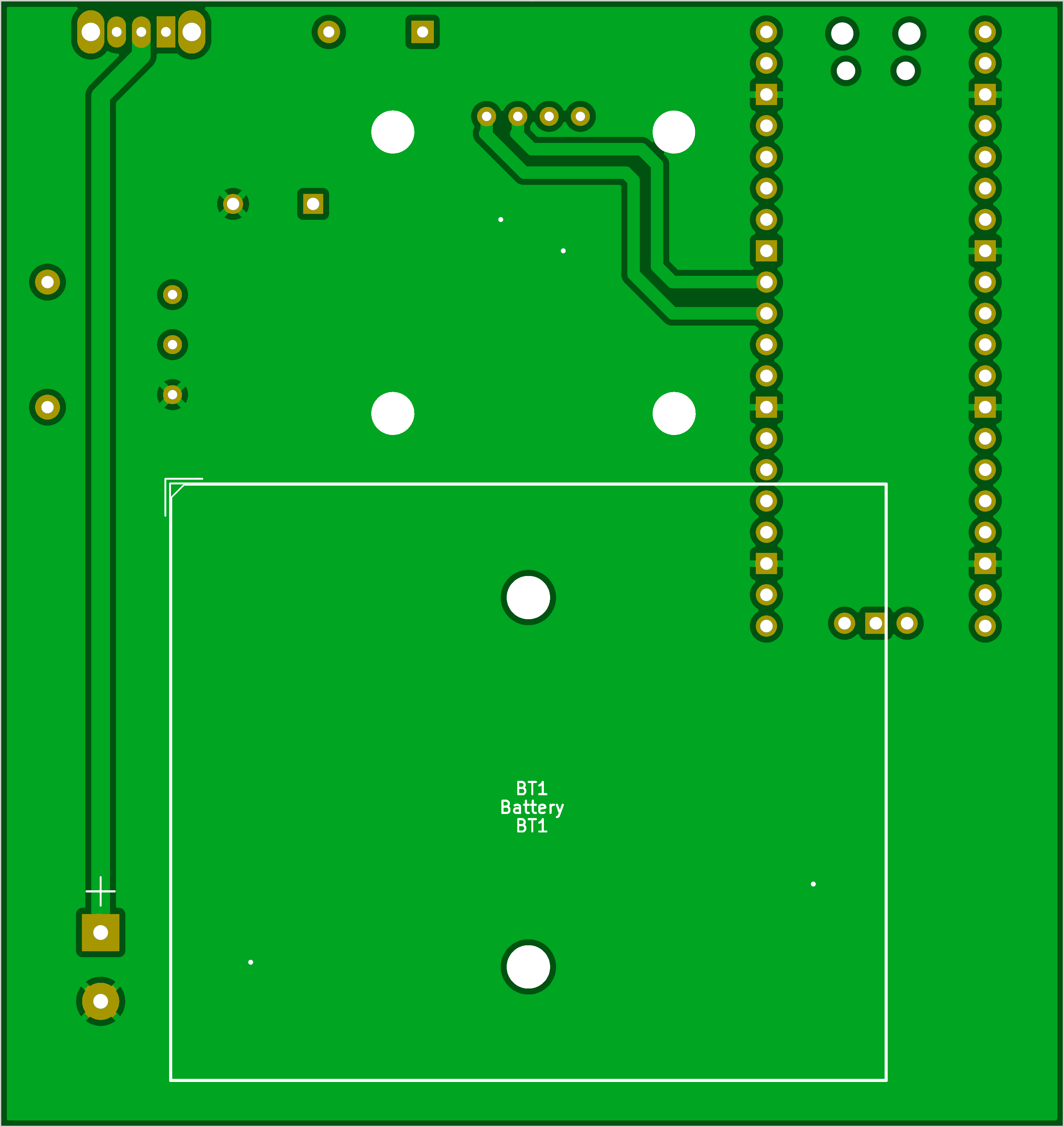 |
|---|
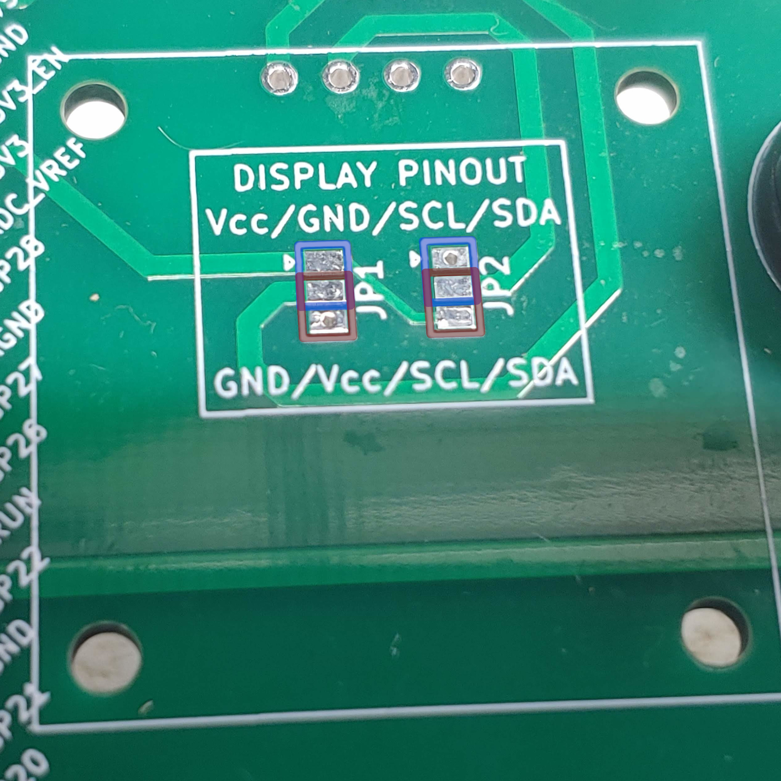
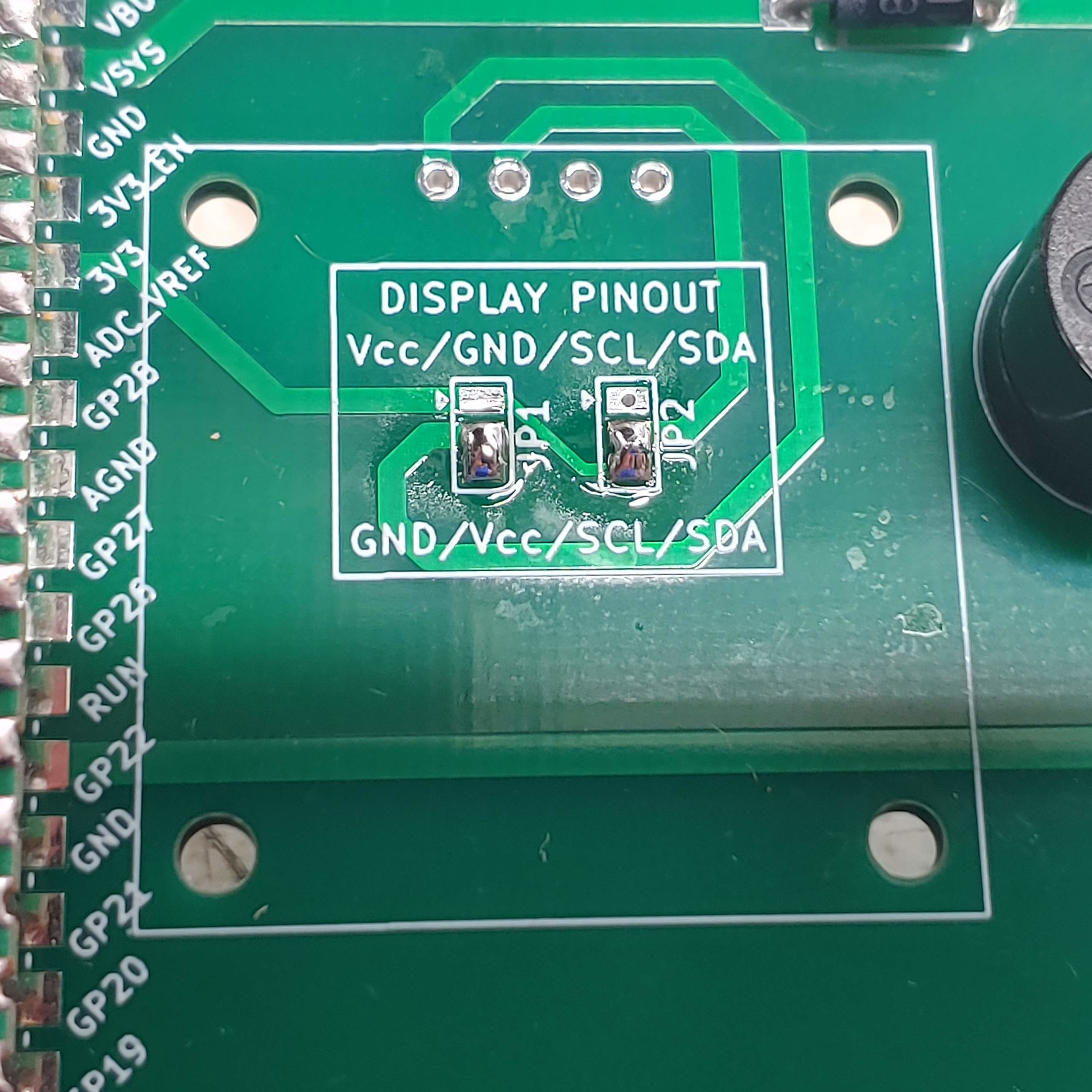
A feature of the PCB is the jumper connections under the display. The I2C OLED displays do not all have the same pin layout. When you buy a display online, the item you receive may not have the same pinout as the one in the photos. Due to this inconsistency, I designed the board to work with both pinouts. If your display has the pinout (in order) Vcc/GND/SCL/SDA then you need to use solder to bridge the middle pads to the upper pads (shown in blue below). If it is GND/Vcc/SCL/SDA then you need to bridge the middle pads to the lower pads (shown in red below). Once you have done this, use Kapton tape to insulate the solder bridges and prevent them from causing a short circuit on the back of the display.
 |  |
|---|
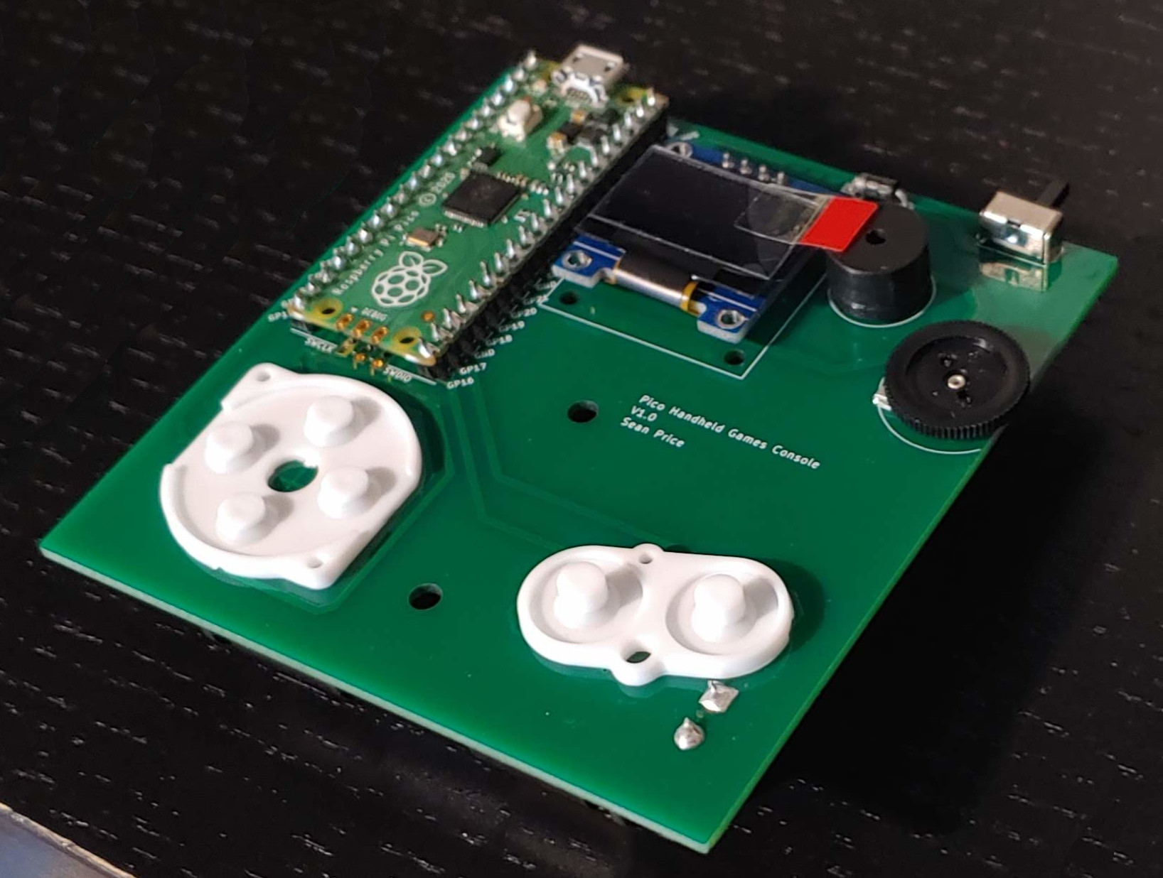
To program the board in the Arduino IDE, I used the arduino-pico board manager. I installed this using the method shown in the arduino-pico repository.
For programming the Pico using MicroPython, I followed the fantastic Official Raspberry Pi Foundation Documentation. Before this project, I had never used MicroPython, and the information provided was very helpful.
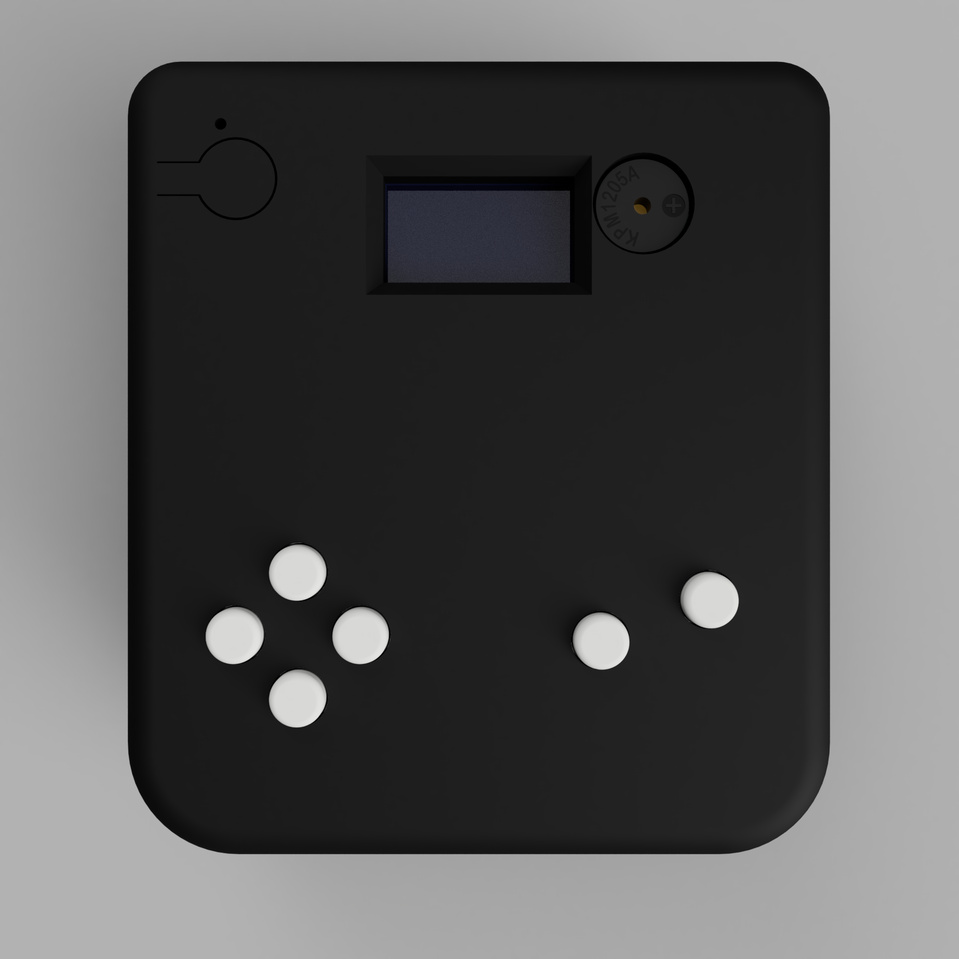
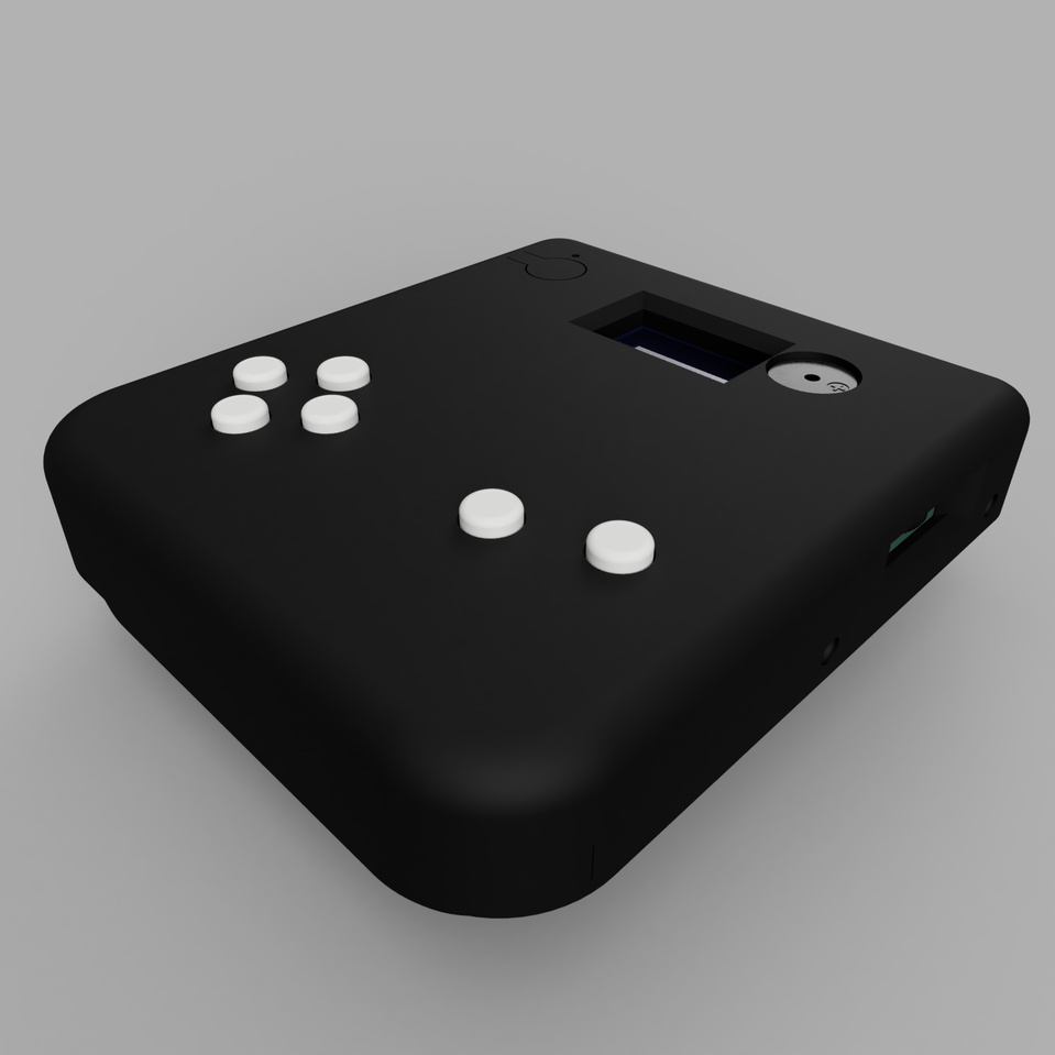
This repository includes code to test that the buttons, buzzer and display are working correctly. There are two versions; one is an Arduino sketch, and the other is written in MicroPython. When you press a button, the buzzer will sound, and the display will show the name of the button pressed. Recognised buttons are as follows:
 |  |
|---|
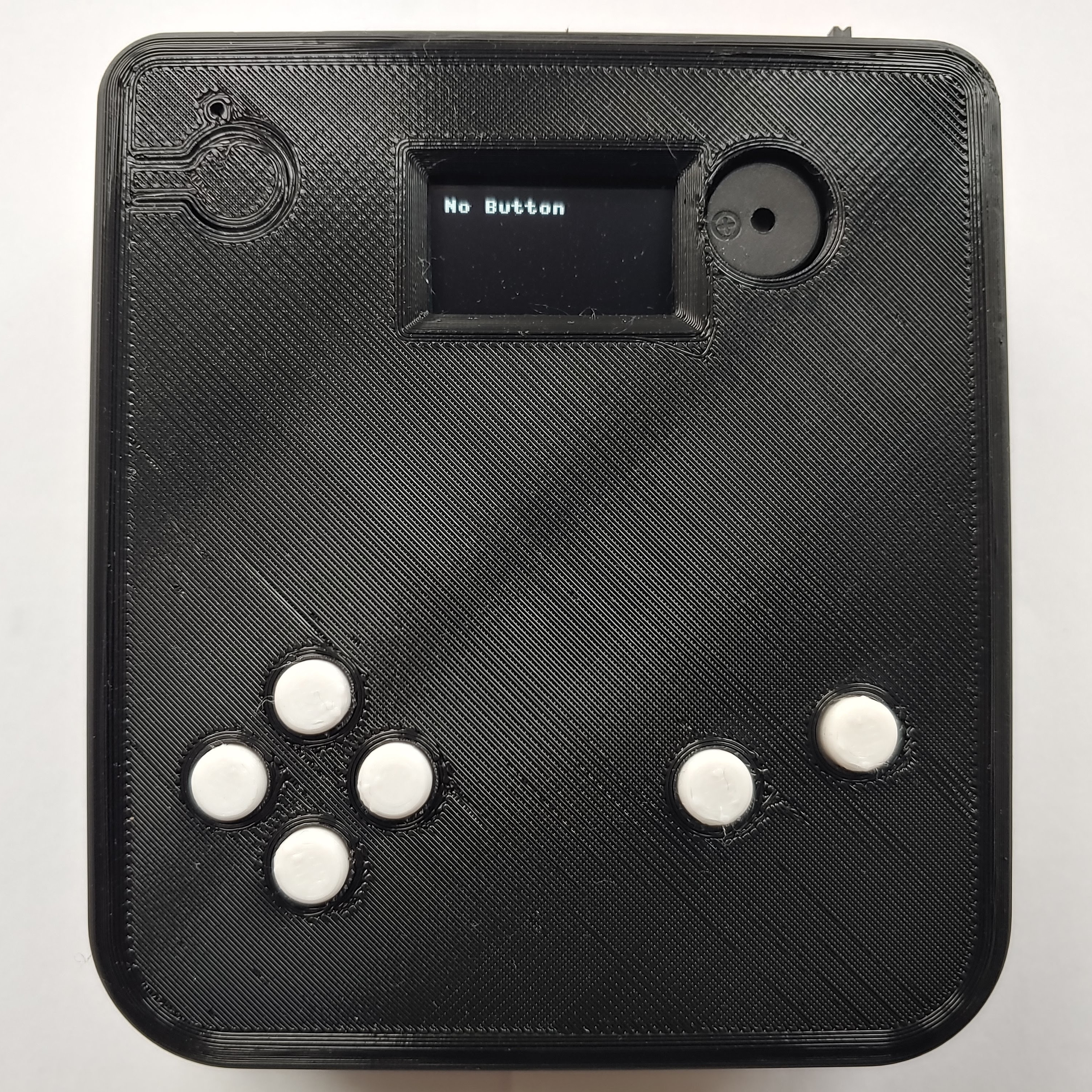 | 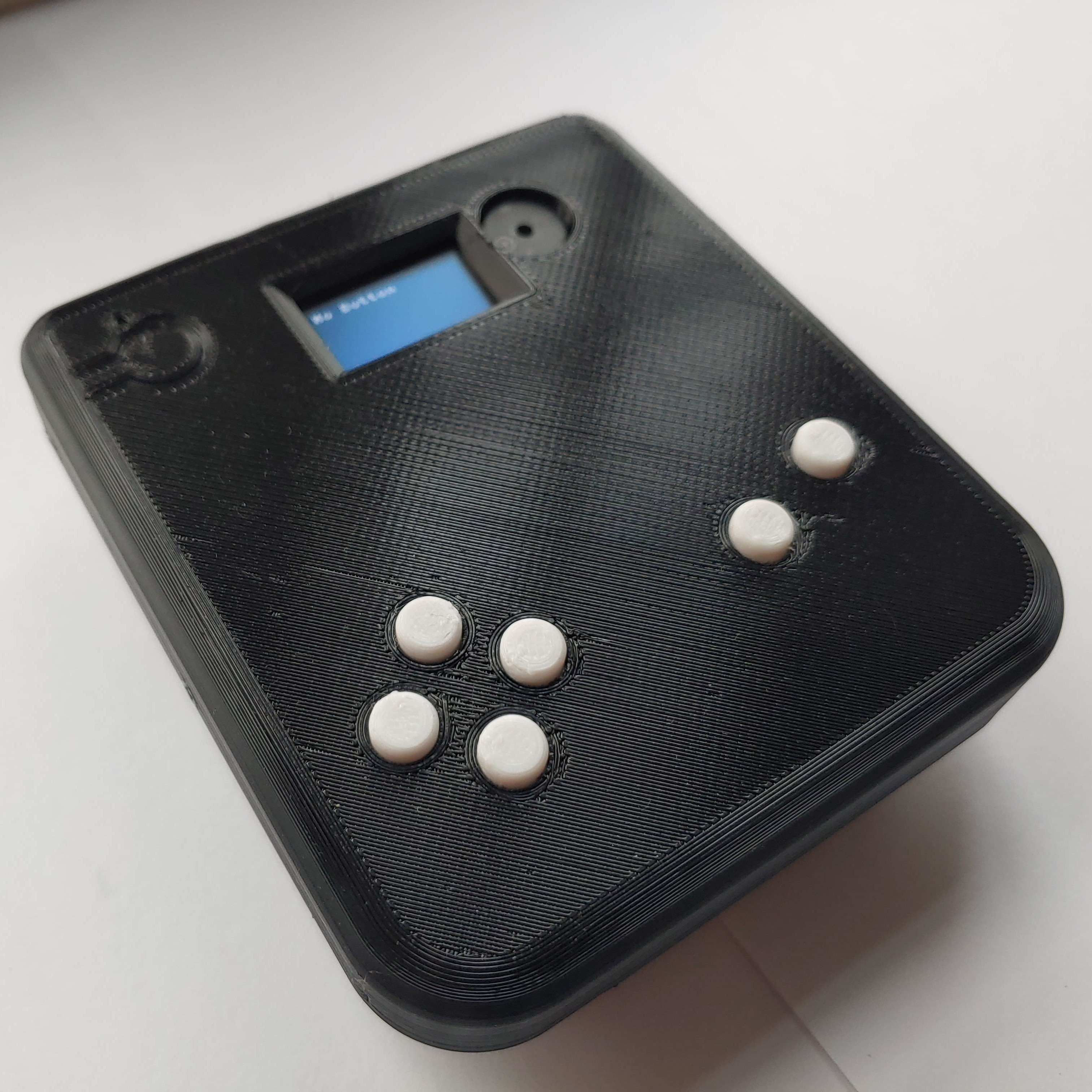 |
|---|---|
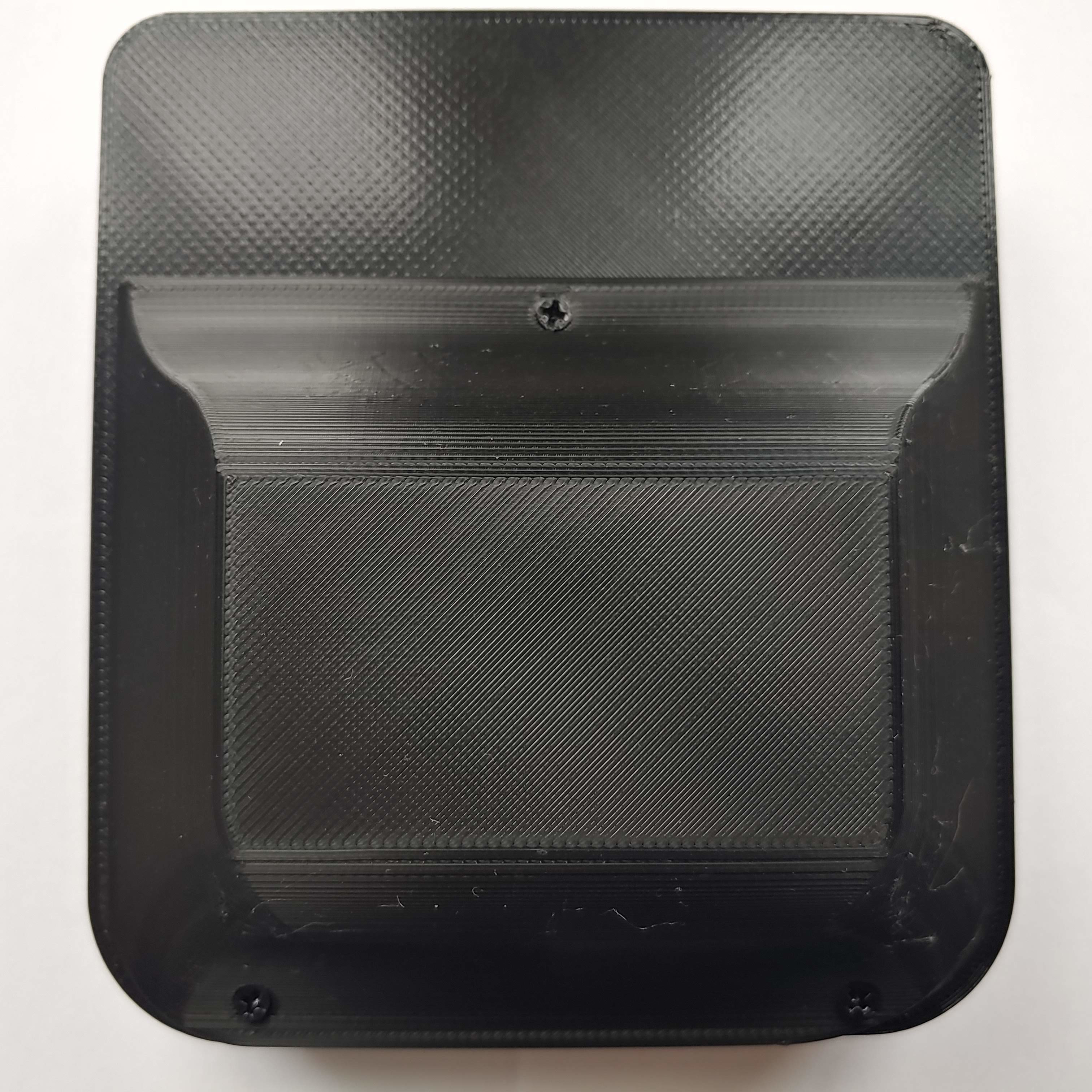 | 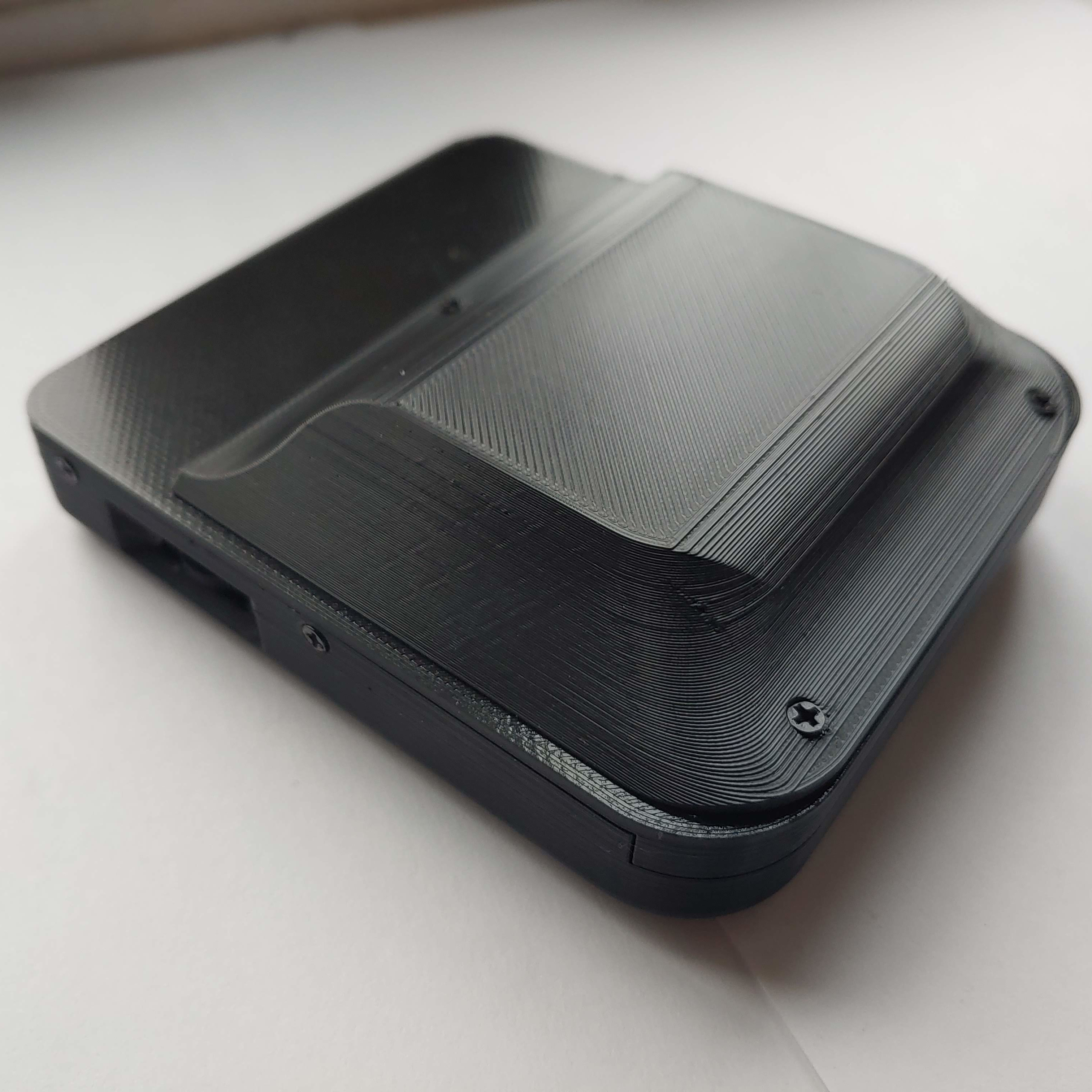 |
Currently, there are no games for the Pico Handheld Games Console. If you make any games for this console, please do a "fork and pull request" to add a link to the repository for your game in this section.
This project has achieved its goal of being a more accessible, USB-programmable alternative to my ATtiny Handheld Games Console.
In future, I would like to push this concept further to make a more advanced console with a larger, colour LCD. I am researching suitable LCDs which can be driven by the Pico (with a frame buffer). To follow the development of this version of the project, please see the "LCD_Version" branch.
| Qty | Value | Footprint | References |
|---|---|---|---|
| 2 | SolderJumper_3_Open | Jumper:SolderJumper-3_P1.3mm_Open_Pad1.0x1.5mm | JP1, JP2 |
| 1 | 0.91_128x64_SSD1306_Oled_Display | 0.91_128x64_SSD1306_Oled_Display:0.91_128x64_SSD1306_Oled_Display | U3 |
| 1 | A | Silicone_Button_Pad:Silicone_Button_Pad | SW7 |
| 1 | B | Silicone_Button_Pad:Silicone_Button_Pad | SW6 |
| 1 | Battery | 3xAA_Battery_Holder:3xAA_Battery_Holder | BT1 |
| 1 | Buzzer | Buzzer_Beeper:MagneticBuzzer_ProSignal_ABT-410-RC | BZ1 |
| 1 | DOWN | Silicone_Button_Pad:Silicone_Button_Pad | SW3 |
| 1 | D_Schottky | Diode_THT:D_A-405_P7.62mm_Horizontal | D1 |
| 1 | LEFT | Silicone_Button_Pad:Silicone_Button_Pad | SW4 |
| 1 | Pico | MCU_RaspberryPi_and_Boards:RPi_Pico_SMD_TH | U1 |
| 1 | RIGHT | Silicone_Button_Pad:Silicone_Button_Pad | SW5 |
| 1 | SW_SPDT | Button_Switch_THT:SW_Slide_1P2T_CK_OS102011MS2Q | SW2 |
| 1 | UP | Silicone_Button_Pad:Silicone_Button_Pad | SW1 |
| 1 | Volume_Wheel | Volume_Wheel:Volume_Wheel | U2 |
google/mozc-devices
Circuit diagrams and firmware source code for Gboard DIY keyboards

hoglet67/RGBtoHDMI
Bare-metal Raspberry Pi project that provides pixel-perfect sampling of Retro Computer RGB/YUV video and conversion to HDMI

mntmn/amiga2000-gfxcard
MNT VA2000, an Open Source Amiga 2/3/4000 Graphics Card (Zorro II/III), written in Verilog

hackclub/OnBoard
💡 Join 1,000 teenagers and make your first PCB with a $100 grant!

kenp-io/not-for-airpods-repairs
The content of this repository is licensed under the WTFPL License. Please have a close look at the terms before using this material.

Luos-io/luos_engine
Open-source and real-time orchestrator for cyber-physical-systems, to easily design, test and deploy embedded applications and digital twins.

Chrismettal/EleLab_v2
Cheap DIY lab system for hobbyists and the tinkering folk

It measures 86.4 × 91.4 mm and has 2 copper layers, 1.6 mm thick.
15 parts. The full list of its parts is on this page, with links to each part's symbol and footprint where PCBKit's library has them.
From the SeanP2001/pico-handheld-games-console repository on GitHub, at the commit this page was made from: the board is PCB/Pico_Handheld/Pico_Handheld.kicad_pcb and its schematic PCB/Pico_Handheld/Pico_Handheld.kicad_sch. PCBKit opens the board in the browser, with nothing to install.
Its repository publishes it under the GPL-3.0 licence: you may reuse it on that licence's terms (keep the author's notice, and for a copyleft licence share your changes alike).