2 layers60 × 30 mm
Controller
google/mozc-devices
Circuit diagrams and firmware source code for Gboard DIY keyboards
11 parts3kApache-2.0
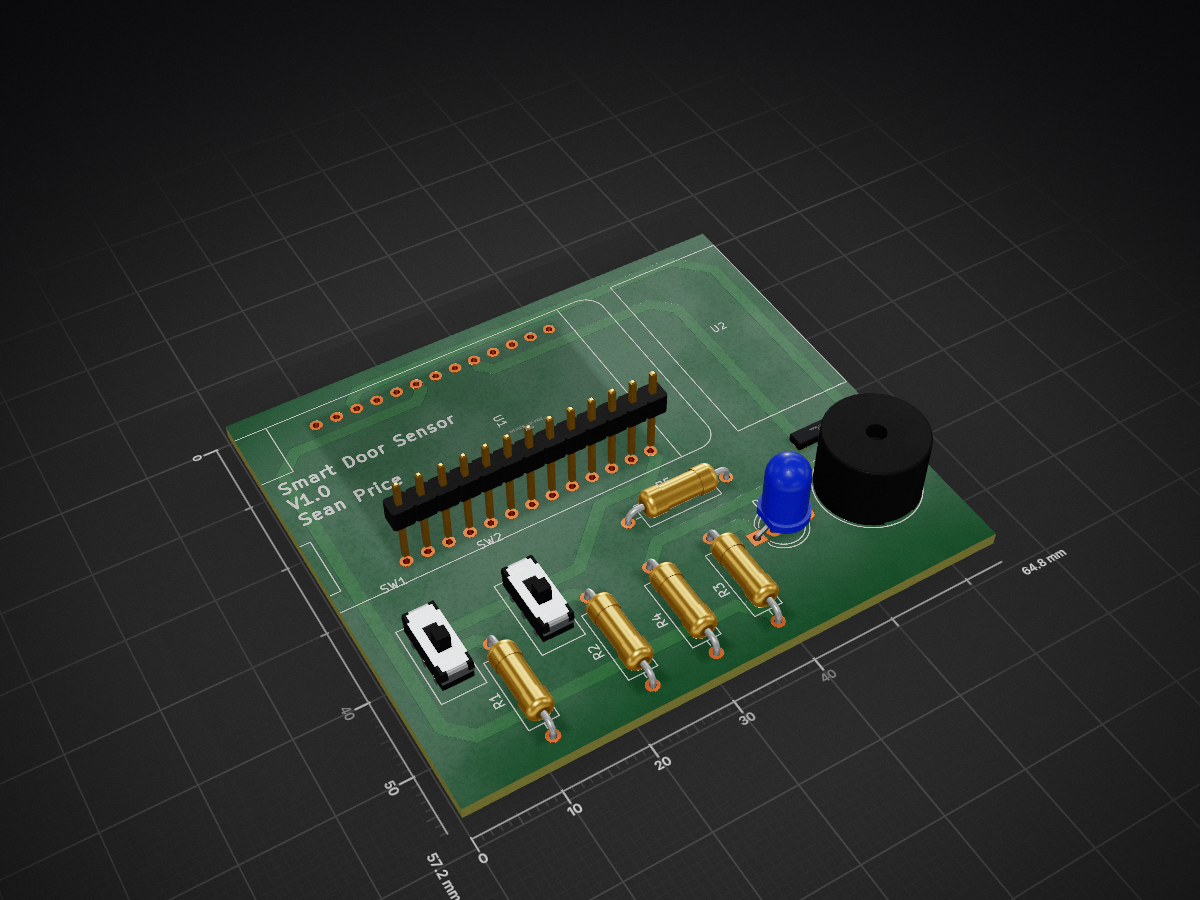
 SeanP2001/Smart_Door_Sensor
A sensor which sends an email notification whenever somebody opens a door.
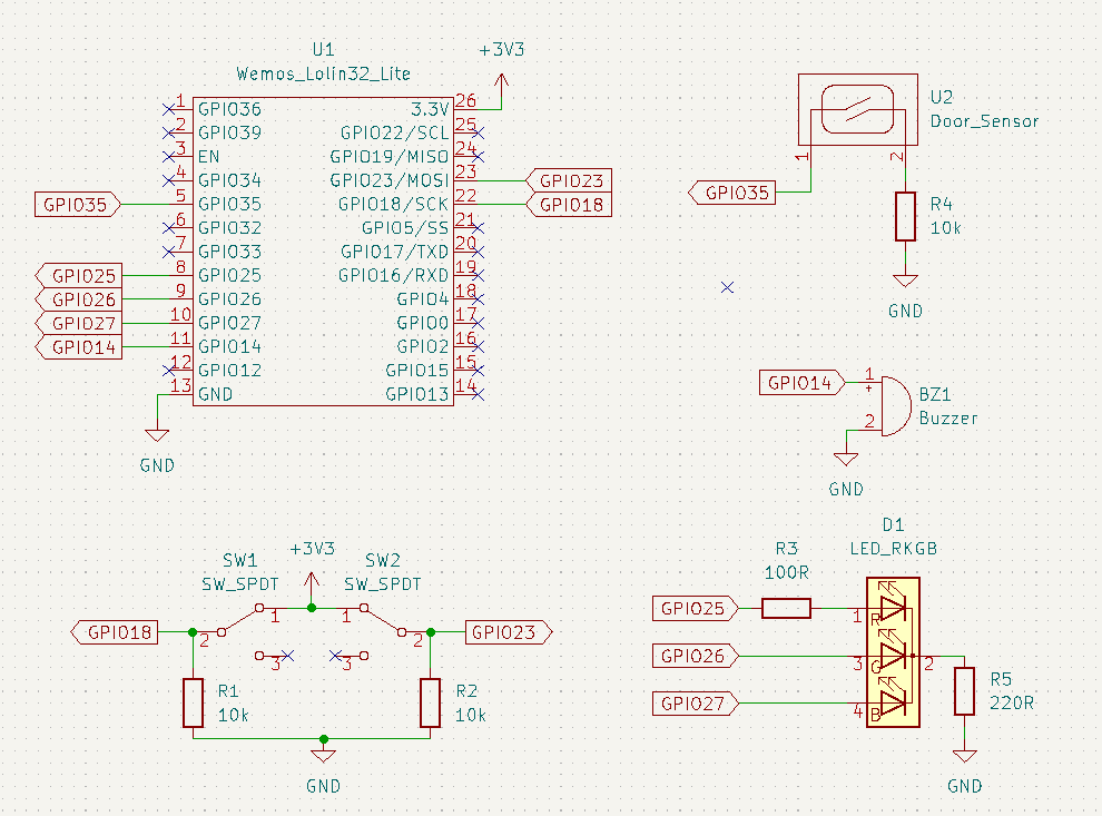
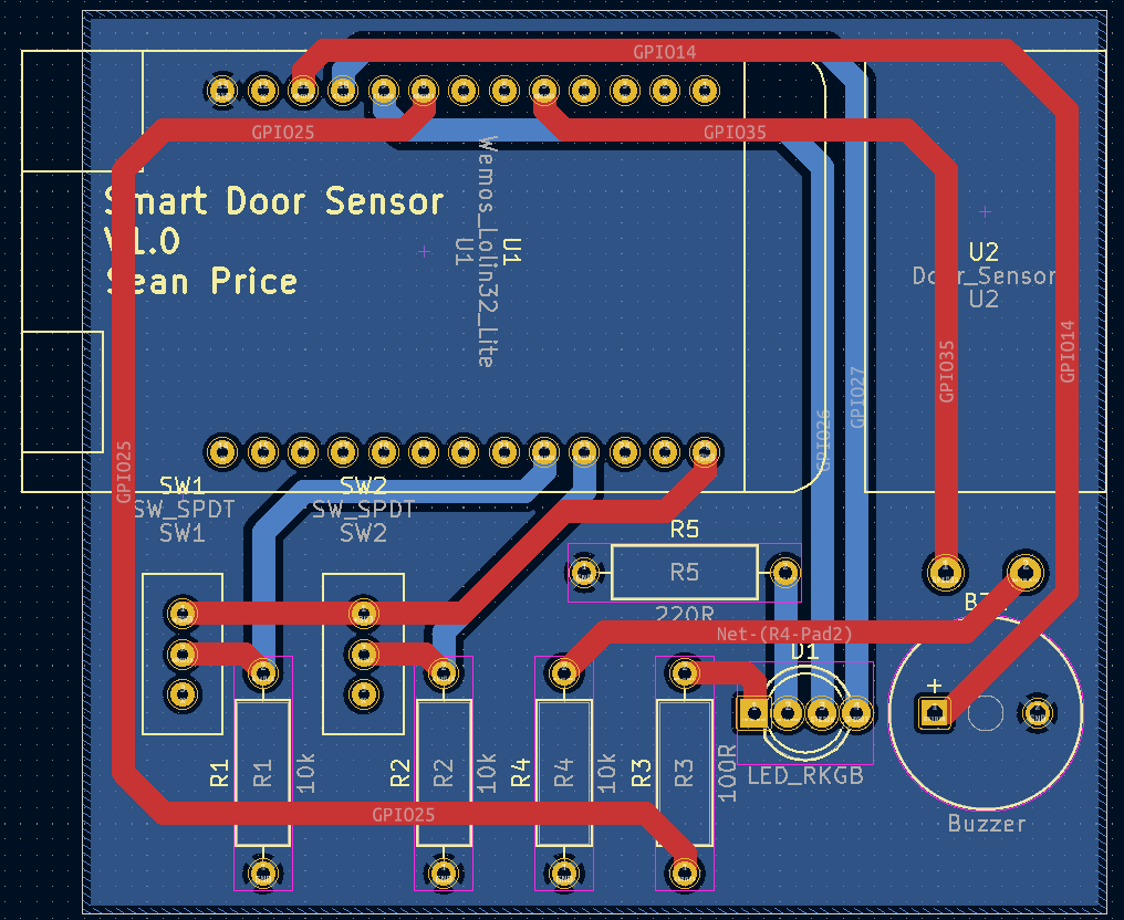
Smart Door Sensor is an open-source printed circuit board by SeanP2001, from the SeanP2001/Smart_Door_Sensor repository on GitHub, published under the GPL-3.0 licence. It is a 2-layer board of 64.8 × 57.2 mm with 11 parts on 31 nets, routed with 57 tracks and 0 vias.
Its parts include 5 resistors, 2 ICs, 2 switches and 1 diode. It belongs with the sensors and measurement and home automation and IoT boards and the ESP32 and ESP8266 boards of this library.
This originally started as a university project, and I have continued to develop this idea in my spare time.
This project is a smart door alarm for security in university accommodation and hotel rooms. When somebody enters the room, the buzzer will sound, or the device will email the user. This standalone device does not require a smart hub to operate.
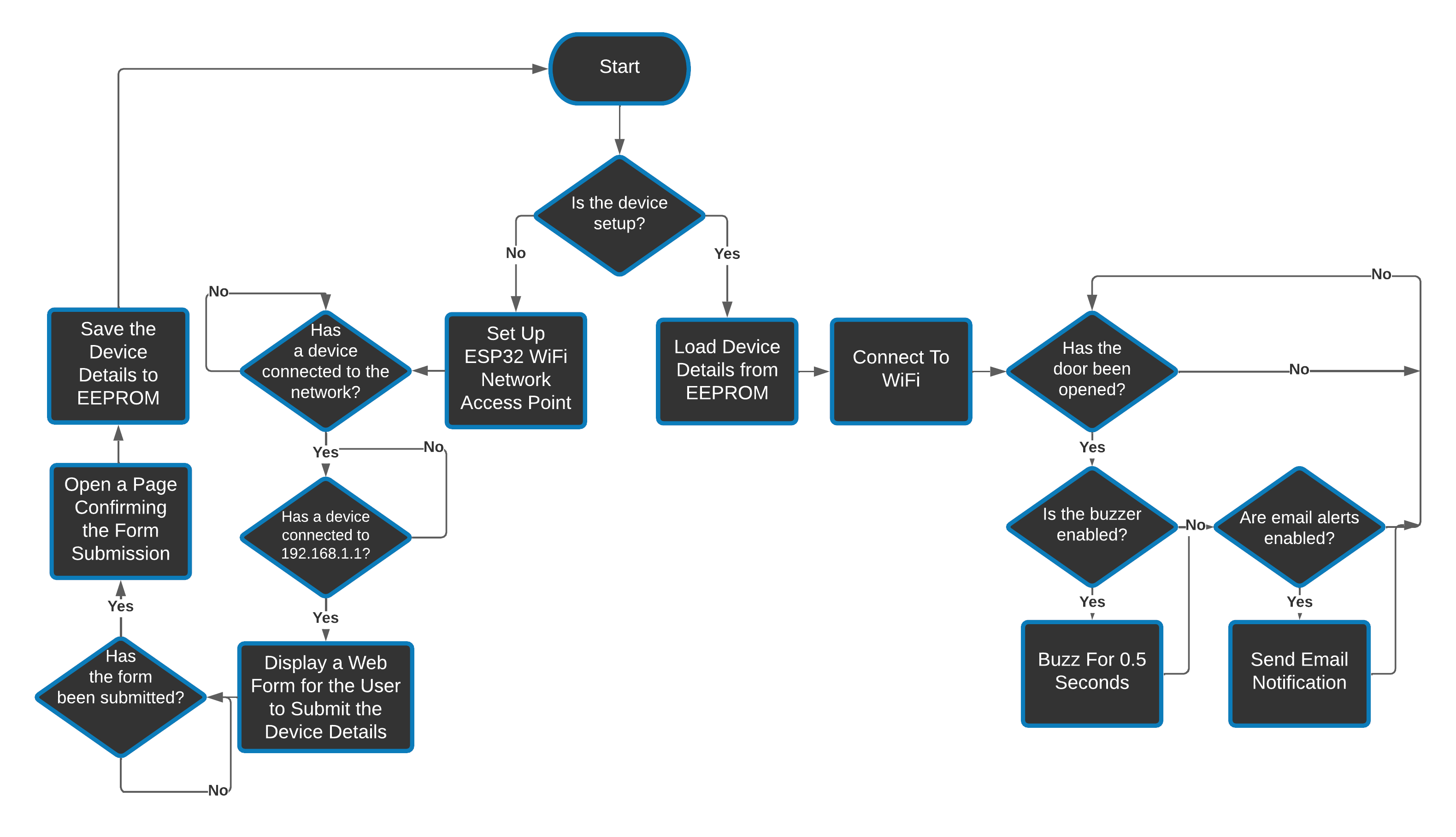
Plug the device into a phone charger and switch the charger on.
Open the Wi-Fi settings on your smartphone and wait for the “S.P.U.D Smart System” network to appear. Once it appears, connect to it.
Turn off mobile data on your phone.
Open your phone’s web browser and enter “192.168.1.1” into the address bar.
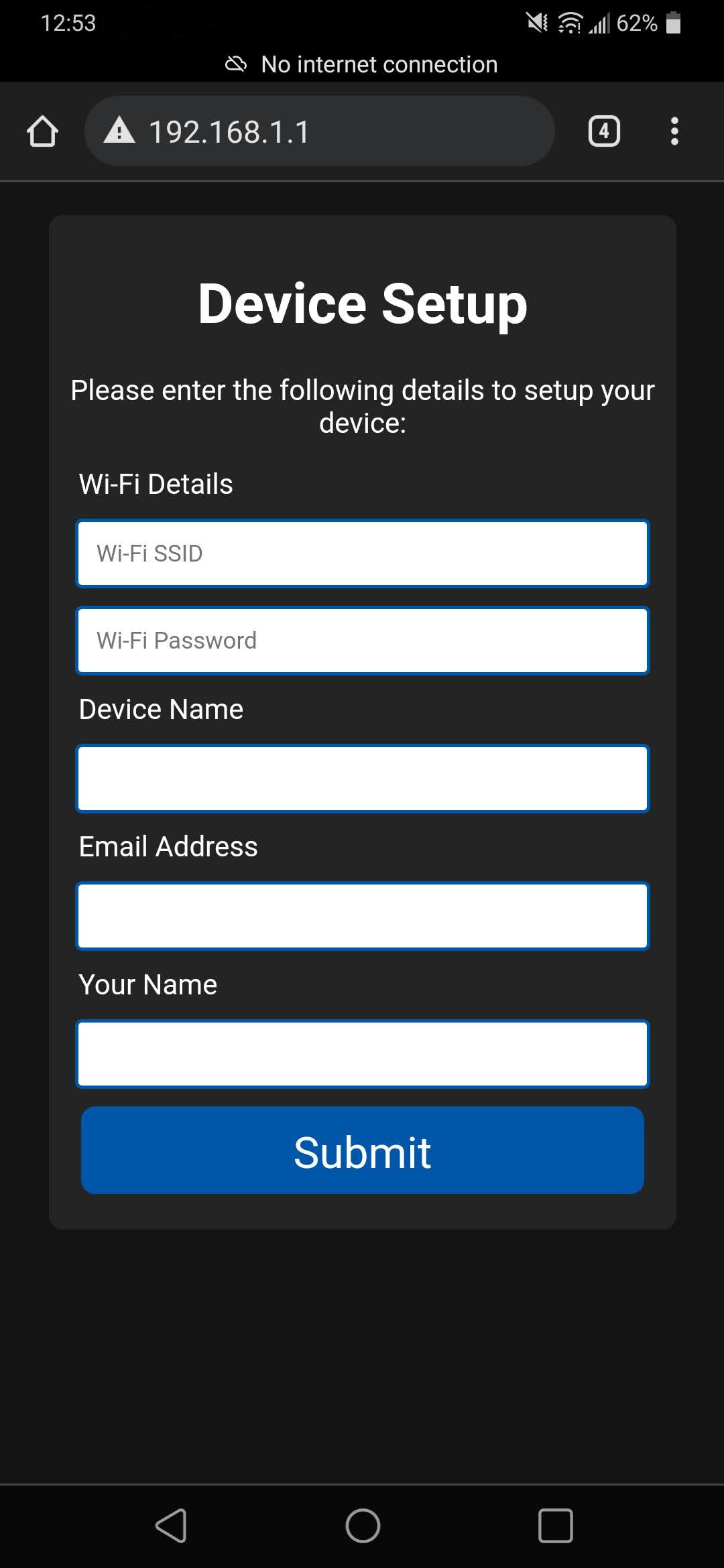
When the page loads, input the following information: • Wi-Fi SSID - The name of your Wi-Fi network • Wi-Fi Password - Often found on the back of your Wi-Fi router • Device Name - The name which you want to give the device e.g., “Front Door” • Email Address - The email address to send notifications to • Your Name - The name which you want to appear on the email notifications
Press “Submit” and check that the credentials displayed on the next page are correct.
Wait for the LED on the device to flash green and then turn off the device and turn it back on again.
Now your device is setup.
Attach the sensor to the back of the door. Peel the sticky back off the main body and stick it to the edge of the door. Stick the magnetic contact to the door frame, as close to the sensor as possible. (Image showing device attached to door)
Open the door ensuring that the device does not catch on the door.
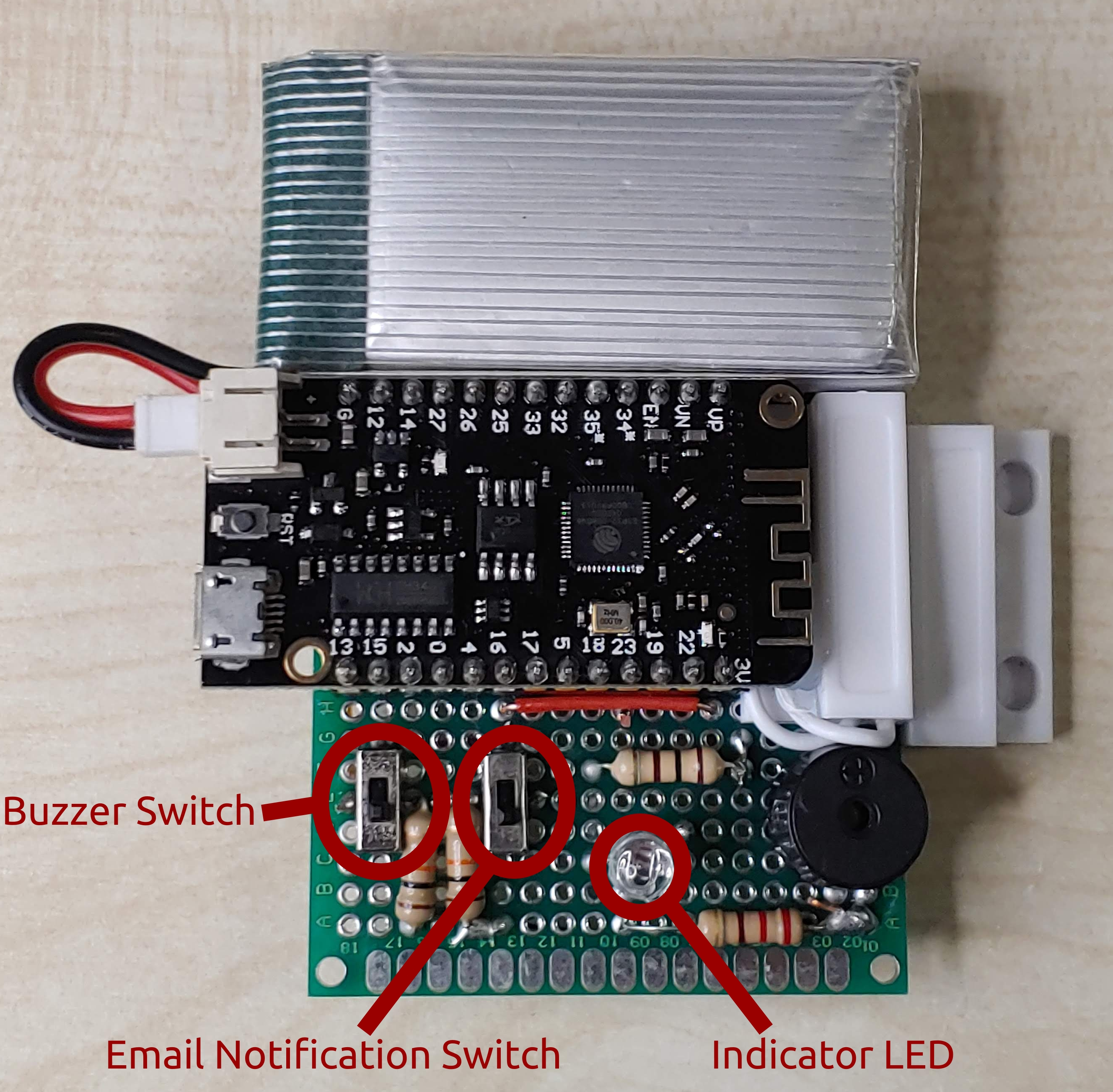
Switching either of the switches will alter the settings and cause the indicator LED to light (The colour of the LED shows which setting has changed).
| Indicator LED Colour | Meaning |
|---|---|
| Blue | Buzzer ON |
| Yellow | Buzzer OFF |
| Green | Email Notifications ON |
| Red | Email Notifications OFF |
Depending on the settings, the sensor will either buzz or send an email notification when the door is opened.
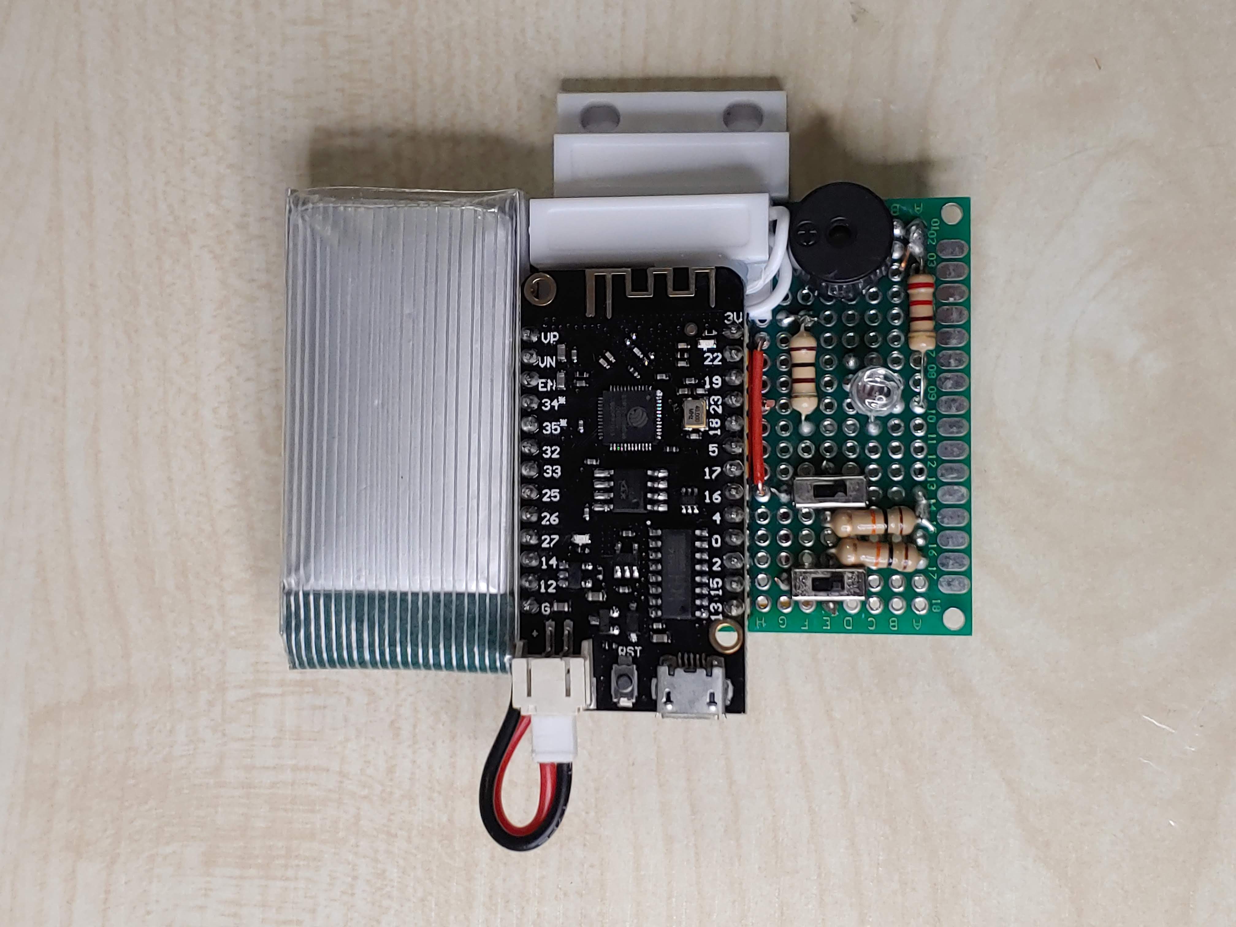 | 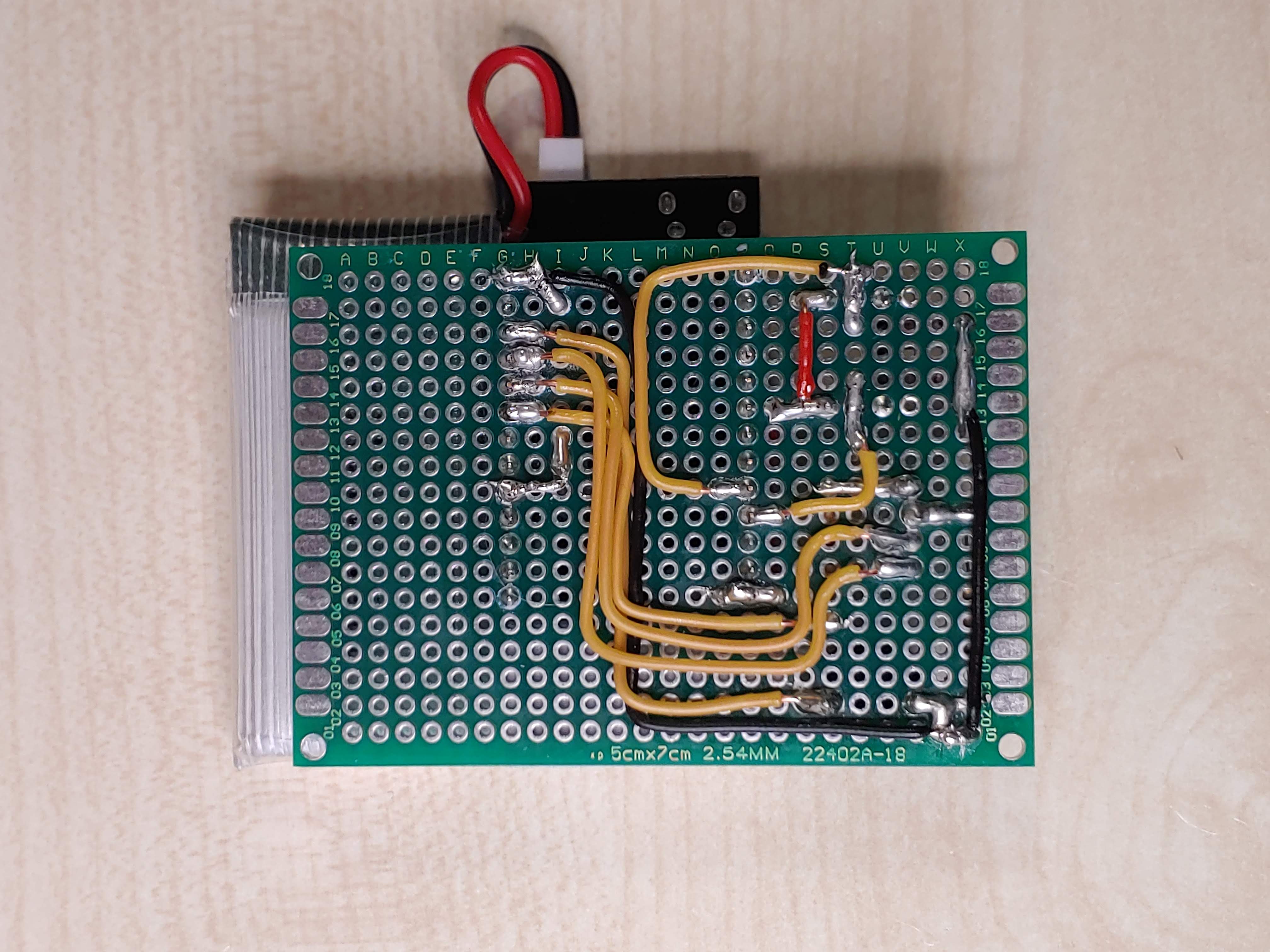 |
|---|
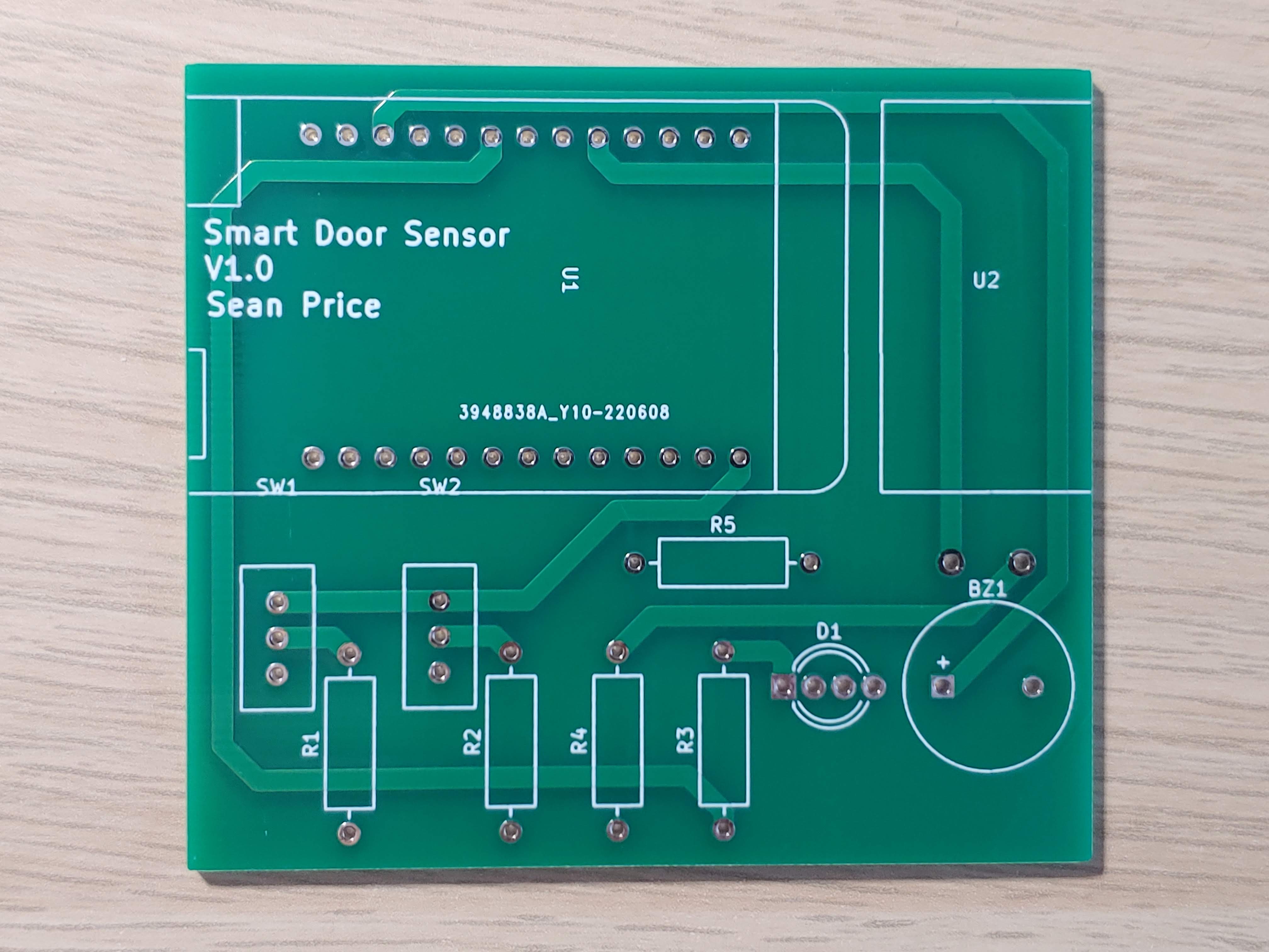 | 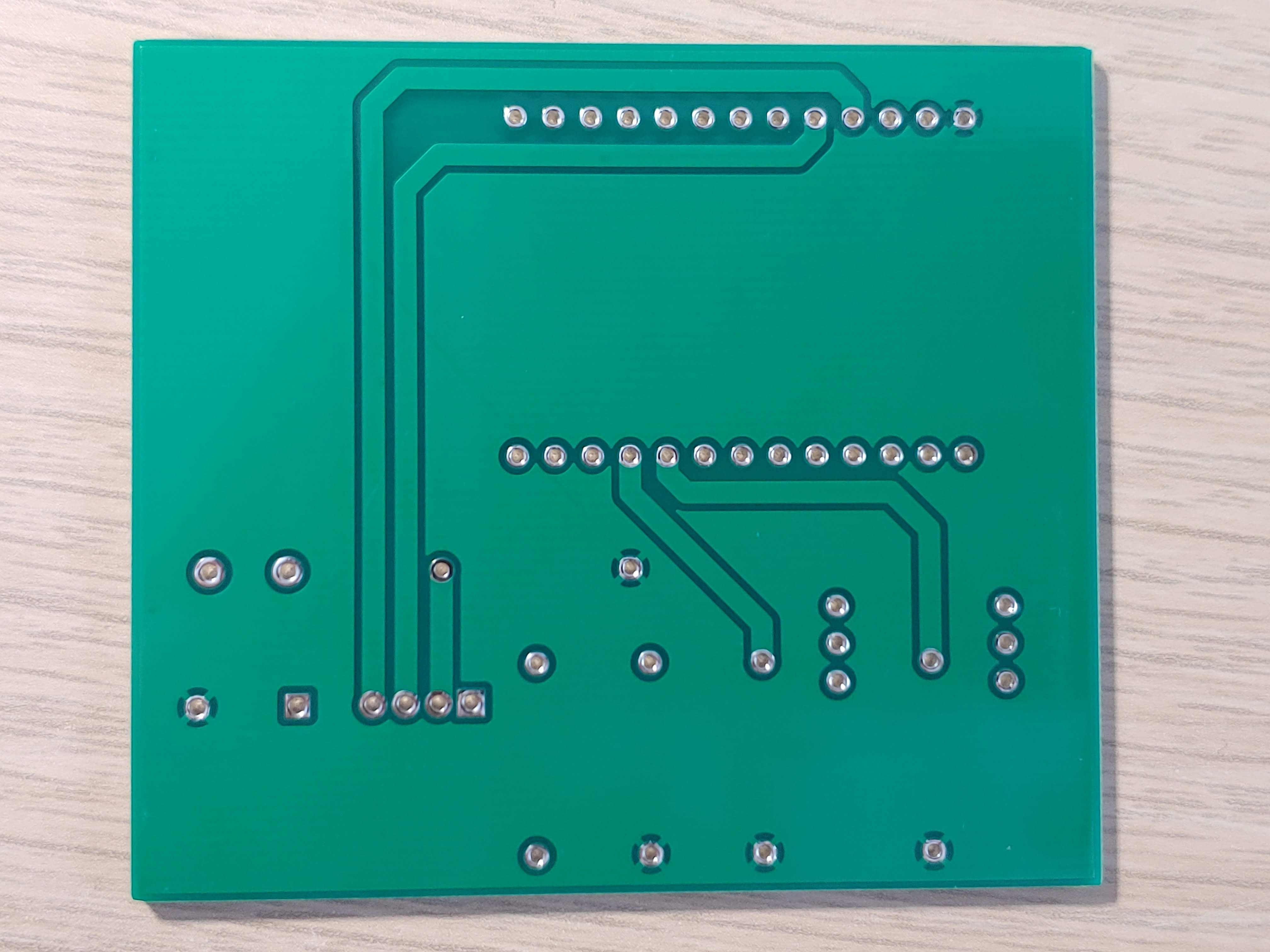 |
|---|
I will be working to re-design the board for this project. I want to use a latch to power the microcontroller when the door is opened and power it off once it has sent the email. This will reduce power consumption.
| Qty | Value | Footprint | References |
|---|---|---|---|
| 3 | 10k | Resistor_THT:R_Axial_DIN0309_L9.0mm_D3.2mm_P12.70mm_Horizontal | R1, R2, R4 |
| 2 | SW_SPDT | Parts_Library:SPDT_Slide_Switch | SW1, SW2 |
| 1 | 100R | Resistor_THT:R_Axial_DIN0309_L9.0mm_D3.2mm_P12.70mm_Horizontal | R3 |
| 1 | 220R | Resistor_THT:R_Axial_DIN0309_L9.0mm_D3.2mm_P12.70mm_Horizontal | R5 |
| 1 | Buzzer | Buzzer_Beeper:MagneticBuzzer_ProSignal_ABT-410-RC | BZ1 |
| 1 | Door_Sensor | Parts_Library:Door_Sensor | U2 |
| 1 | LED_RKGB | LED_THT:LED_D5.0mm-4_RGB_Wide_Pins | D1 |
| 1 | Wemos_Lolin32_Lite | Parts_Library:Wemos_Lolin32_Lite | U1 |
google/mozc-devices
Circuit diagrams and firmware source code for Gboard DIY keyboards


FrameworkComputer/ExpansionCards
Reference designs and documentation to create Expansion Cards for the Framework Laptop

hoglet67/RGBtoHDMI
Bare-metal Raspberry Pi project that provides pixel-perfect sampling of Retro Computer RGB/YUV video and conversion to HDMI

hackclub/OnBoard
💡 Join 1,000 teenagers and make your first PCB with a $100 grant!


tardate/LittleArduinoProjects
a collection of "Little Electronic & Arduino Projects", most involving electronics or an Arduino in one way or another!

basilfx/TRADFRI-Hacking
Hacking IKEA TRÅDFRI products, such as light bulbs, window blinds and other accessories.
It measures 64.8 × 57.2 mm and has 2 copper layers, 1.6 mm thick.
11 parts. The full list of its parts is on this page, with links to each part's symbol and footprint where PCBKit's library has them.
From the SeanP2001/Smart_Door_Sensor repository on GitHub, at the commit this page was made from: the board is PCB/Smart_Door_Sensor/Smart_Door_Sensor.kicad_pcb and its schematic PCB/Smart_Door_Sensor/Smart_Door_Sensor.kicad_sch. PCBKit opens the board in the browser, with nothing to install.
Its repository publishes it under the GPL-3.0 licence: you may reuse it on that licence's terms (keep the author's notice, and for a copyleft licence share your changes alike).