2 layers45 × 45 mm
Watch
DINDIN2007/Blystwatch
This is a demo board to showcase development with both the BlystL15 (based on the nrf54L15) and the IOComposer AI from I-Syst.inc.
47 parts

 Scrarf/PCB_For_FPGA_Path_Tracer1
A PCB for FPGA Path tracer project.
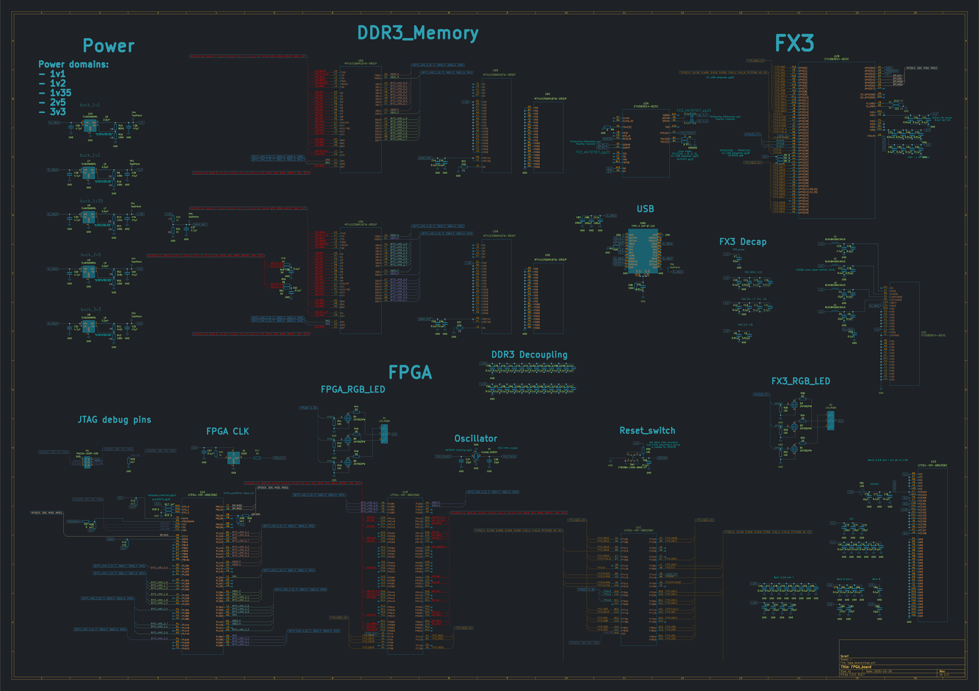
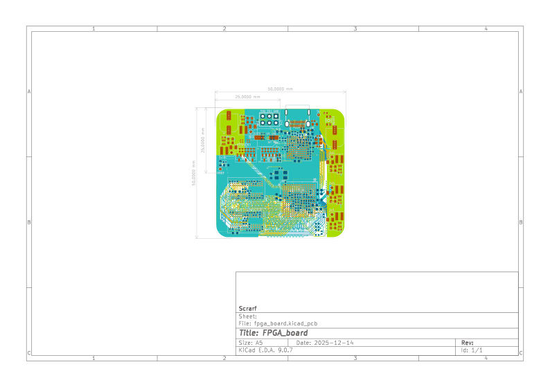
Fpga board is an open-source printed circuit board by Scrarf, from the Scrarf/PCB_For_FPGA_Path_Tracer repository on GitHub. It is an 8-layer board of 50 × 50 mm with 206 parts on 316 nets, routed with 5,734 tracks and 709 vias.
It is built around the CYUSB3014-BZXC, LFE5U-45F-6BG256C and TLV62569DRL, with the MT41K256M16TW-093:P, 2N7002PW and 1TS028A-1300-0600-CT among its other parts. Its parts include 114 capacitors, 53 resistors, 9 ICs, 9 inductors and 6 transistors. It belongs with the fPGA and programmable logic boards and the FPGA and CPLD boards of this library.


| Qty | Value | Footprint | References |
|---|---|---|---|
| 72 | 0.1µF | Capacitor_SMD:C_0402_1005Metric | C1, C10, C100, C101, C102, C103, C104, C105, C106, C107, C108, C109, C110, C111, C112, C113 +56 |
| 11 | 0.01µF | Capacitor_SMD:C_0402_1005Metric | C8, C9, C11, C18, C19, C22, C23, C26, C61, C89, C90 |
| 10 | 0 | Resistor_SMD:R_0402_1005Metric | R3, R4, R5, R6, R7, R8, R18, R19, R26, R27 |
| 9 | 22µF | Capacitor_SMD:C_0603_1608Metric | C4, C5, C7, C53, C54, C55, C66, C80, C82 |
| 7 | 100k | Resistor_SMD:R_0603_1608Metric | R9, R10, R12, R14, R16, R38, R53 |
| 7 | 10k | Resistor_SMD:R_0402_1005Metric | R30, R31, R33, R35, R41, R42, R43 |
| 7 | 4.7µF | Capacitor_SMD:C_0402_1005Metric | C15, C29, C31, C33, C35, C37, C63 |
| 7 | TestPoint | TestPoint:TestPoint_Pad_D1.0mm | TP1, TP2, TP3, TP4, TP5, TP6, TP7 |
| 6 | 2N7002PW | Package_TO_SOT_SMD:SOT-323_SC-70 | Q1, Q2, Q3, Q4, Q5, Q6 |
| 5 | 10µF | Capacitor_SMD:C_0402_1005Metric | C73, C74, C75, C76, C86 |
| 5 | 2.2µH | Inductor:IND_VLS3015_TDK | L5, L6, L7, L8, L9 |
| 5 | 20 | Resistor_SMD:R_0402_1005Metric | R32, R34, R45, R46, R47 |
| 5 | 47µF | Capacitor_SMD:C_0805_2012Metric | C30, C32, C34, C36, C64 |
| 5 | 4k7 | Resistor_SMD:R_0402_1005Metric | R17, R23, R25, R28, R29 |
| 5 | TLV62569DRL | Package_TO_SOT_SMD:SOT-563 | U3, U7, U8, U9, U10 |
| 4 | 50 | Resistor_SMD:R_0402_1005Metric | R48, R49, R50, R51 |
| 4 | BLM18KG601SN1D | Inductor_SMD:L_0603_1608Metric | L1, L2, L3, L4 |
| 3 | 100μF | Capacitor_SMD:CP_Elec_6.3x5.4 | C87, C88, C114 |
| 3 | 1k | Resistor_SMD:R_0603_1608Metric | R20, R21, R24 |
| 2 | 15pF | Capacitor_SMD:C_0402_1005Metric | C27, C28 |
| 2 | 240 | Resistor_SMD:R_0603_1608Metric | R22, R37 |
| 2 | 62 | Resistor_SMD:R_0402_1005Metric | R36, R44 |
| 2 | LED_RGBA | LED_SMD:LED_Wurth_150044M155260 | D1, D2 |
| 2 | MT41K256M16TW-093:P | Package_BGA:Micron_FBGA-96_9x14mm_Layout9x16_P0.8mm | U5, U6 |
| 1 | 120 | Inductor_SMD:L_0603_1608Metric | FB1 |
| 1 | 124k | Resistor_SMD:R_0603_1608Metric | R13 |
| 1 | 1TS028A-1300-0600-CT | BUTTON:SW-SMD_4P-L2.8-W1.9-P1.20-LS3.0_1TS028A | SW1 |
| 1 | 200 | Resistor_SMD:R_0402_1005Metric | R2 |
| 1 | 319k | Resistor_SMD:R_0603_1608Metric | R52 |
| 1 | 330 | Resistor_SMD:R_0402_1005Metric | R40 |
| 1 | 442k | Resistor_SMD:R_0603_1608Metric | R11 |
| 1 | 5k1 | Resistor_SMD:R_0402_1005Metric | R39 |
| 1 | 6k04 | Resistor_SMD:R_0402_1005Metric | R1 |
| 1 | 82k5 | Resistor_SMD:R_0603_1608Metric | R15 |
| 1 | CYUSB3014-BZXC | Package_BGA:TFBGA-121_10x10mm_Layout11x11_P0.8mm | U2 |
| 1 | Crystal_GND24 | Crystal:Crystal_SMD_2520-4Pin_2.5x2.0mm | Y1 |
| 1 | LFE5U-45F-6BG256C | ECP5:caBGA256_LAT | U1 |
| 1 | PH2.54-2X3P-H25 | PIN-HEADER:HDR-TH_6P-P2.54-V-M-R2-C3-S2.54-1 | H1 |
| 1 | TYPE-C 24P QT 143 | USB-TYPE-C:TYPE-C-SMD_C9900025773 | USB1 |
| 1 | XO32 | Crystal:Crystal_SMD_5032-4Pin_5.0x3.2mm | X1 |
DINDIN2007/Blystwatch
This is a demo board to showcase development with both the BlystL15 (based on the nrf54L15) and the IOComposer AI from I-Syst.inc.

JackToaster/framework_logic_analyzer
16 channel USB 3 Logic analyzer expansion card for Framework laptop

osqzss/PocketSDR
The Pocket SDR FE device includes 2, 4, or 8 RF frontend channels, supporting the GNSS L1 band (1525 - 1610 MHz) or L2/L5/L6 bands (1160 - 1290 MHz). For these signal bands, refer to GNSS Signal Bands.


wzwqoo/fmcw_10ghz_radar
A single-board 1TX / 3RX, 10 GHz FMCW radar, its Artix-7 range–Doppler–CFAR backend, and the carrier board that mounts the radar alongside a global-shutter camera and an impact microphone.


It measures 50 × 50 mm and has 8 copper layers, 1.62 mm thick.
206 parts, built around the CYUSB3014-BZXC, LFE5U-45F-6BG256C, TLV62569DRL and MT41K256M16TW-093:P. The full list of its parts is on this page, with links to each part's symbol and footprint where PCBKit's library has them.
From the Scrarf/PCB_For_FPGA_Path_Tracer repository on GitHub, at the commit this page was made from: the board is fpga_board.kicad_pcb and its schematic fpga_board.kicad_sch. PCBKit opens the board in the browser, with nothing to install.
Its repository states no licence, so its author keeps all rights: ask Scrarf before reusing the design.