
2 layers22 × 45 mm
Smart Watch L15-Dock
DINDIN2007/Blystwatch
This is a demo board to showcase development with both the BlystL15 (based on the nrf54L15) and the IOComposer AI from I-Syst.inc.
9 parts

This is a demo board to showcase development with both the BlystL15 (based on the nrf54L15) and the IOComposer AI from I-Syst.inc.
Watch is an open-source printed circuit board by DINDIN2007, from the DINDIN2007/Blystwatch repository on GitHub. It is a 2-layer board of 45 × 45 mm with 47 parts on 71 nets, routed with 652 tracks and 111 vias.
It is built around the MAX30102EFD+T, OPT3001DNPRQ1 and TMP117AIDRVR, with the W25Q80EWSNIG, BMI323 and NPM1304-QEAA-R7 among its other parts. Its parts include 21 capacitors, 6 ICs, 4 resistors, 4 connectors and 3 switches. It belongs with the wearables boards of this library.


This directory contains the hardware design files, schematics, and board layouts for the Smart-Watch-L15. This device serves as a highly integrated demo board to showcase advanced wearable development utilizing the BlystL15 module (based on the Nordic nRF54L15) and the IOComposer AI from I-Syst Inc.
This prototype design emphasizes ultra-low power consumption, clinical-grade sensor accuracy, and a high-density HDI (High-Density Interconnect) layout suitable for a modern smartwatch form factor. For future improvements to the design, a proper industrial standard touchscreen display would elevate this design to be more "finished".
The smartwatch PCB integrates several specialized ICs to handle processing, power management, and biometric sensing. Here is a breakdown of the primary components, their roles, and specific hardware design constraints.
ALERT pin) if a threshold (e.g., a fever) is crossed, saving significant MCU power.ALERT pin requires a dedicated pull-up resistor and the TMP117 is placed far from the hot PMIC modules to reduce noises.(The following screenshots highlight the routing, schematic logic, and physical form factor of the Smart-Watch-L15).
The system is divided into logical blocks to isolate power, sensing, and processing.
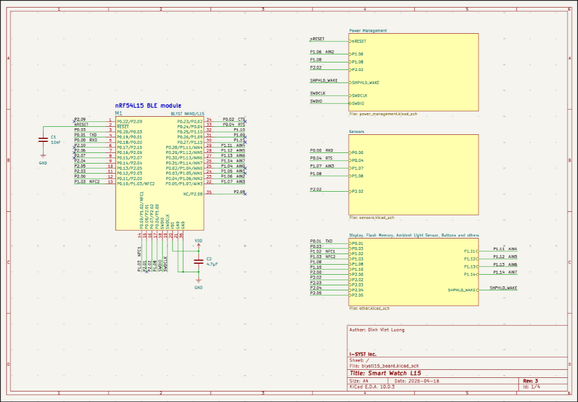 Fig 1: BlystL15 MCU.
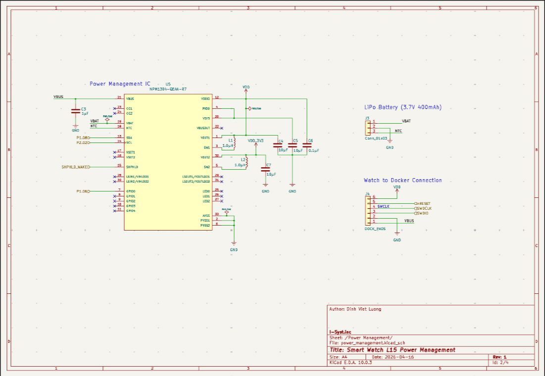 Fig 2: nPM1304 PMIC, Battery and Dock Connectors.
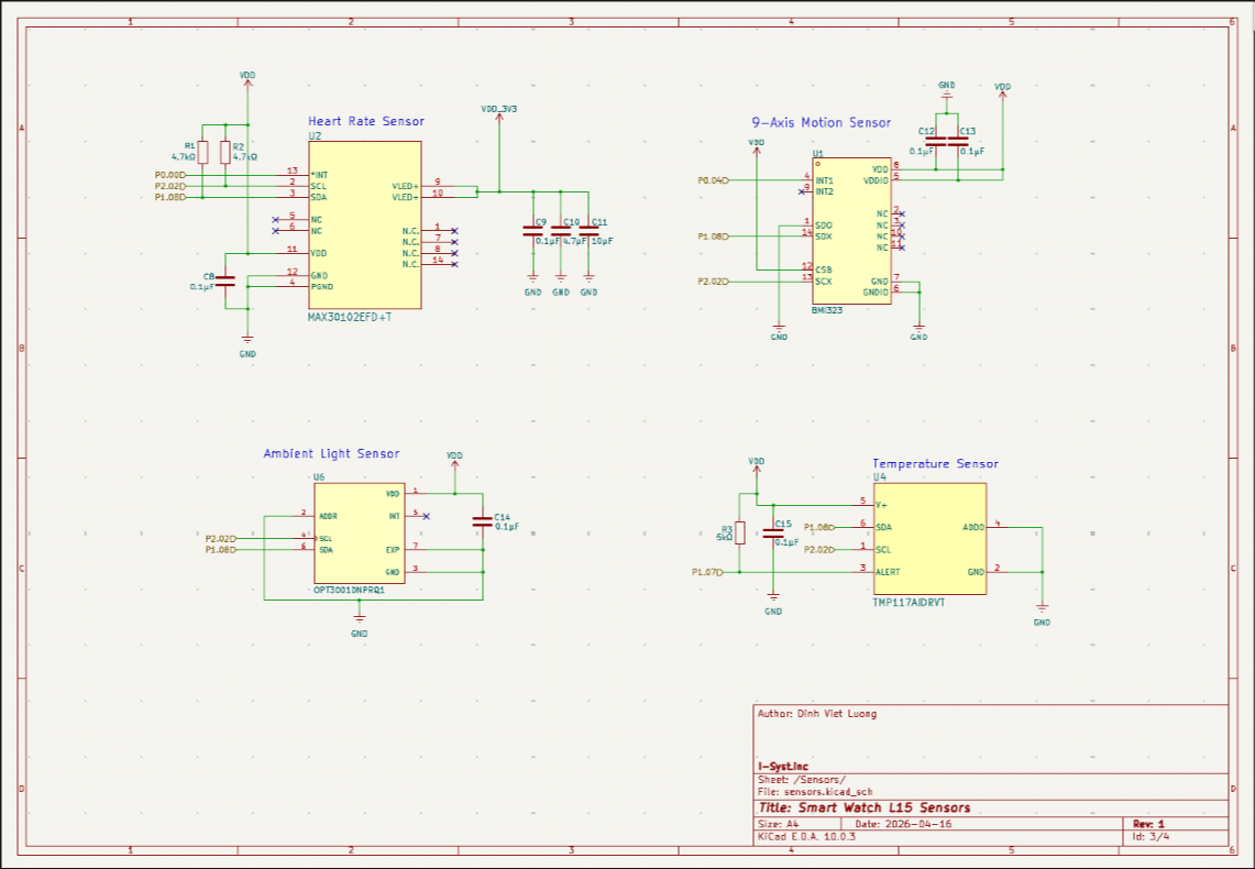 Fig 3: Sensors including the LSM6DSV80X (6-axis motion sensor), MAX30102 (Pulse Oximeter and Heart Rate), TMP117 (Temperature Sensor), and OPT3001-Q1 (Light Sensor).
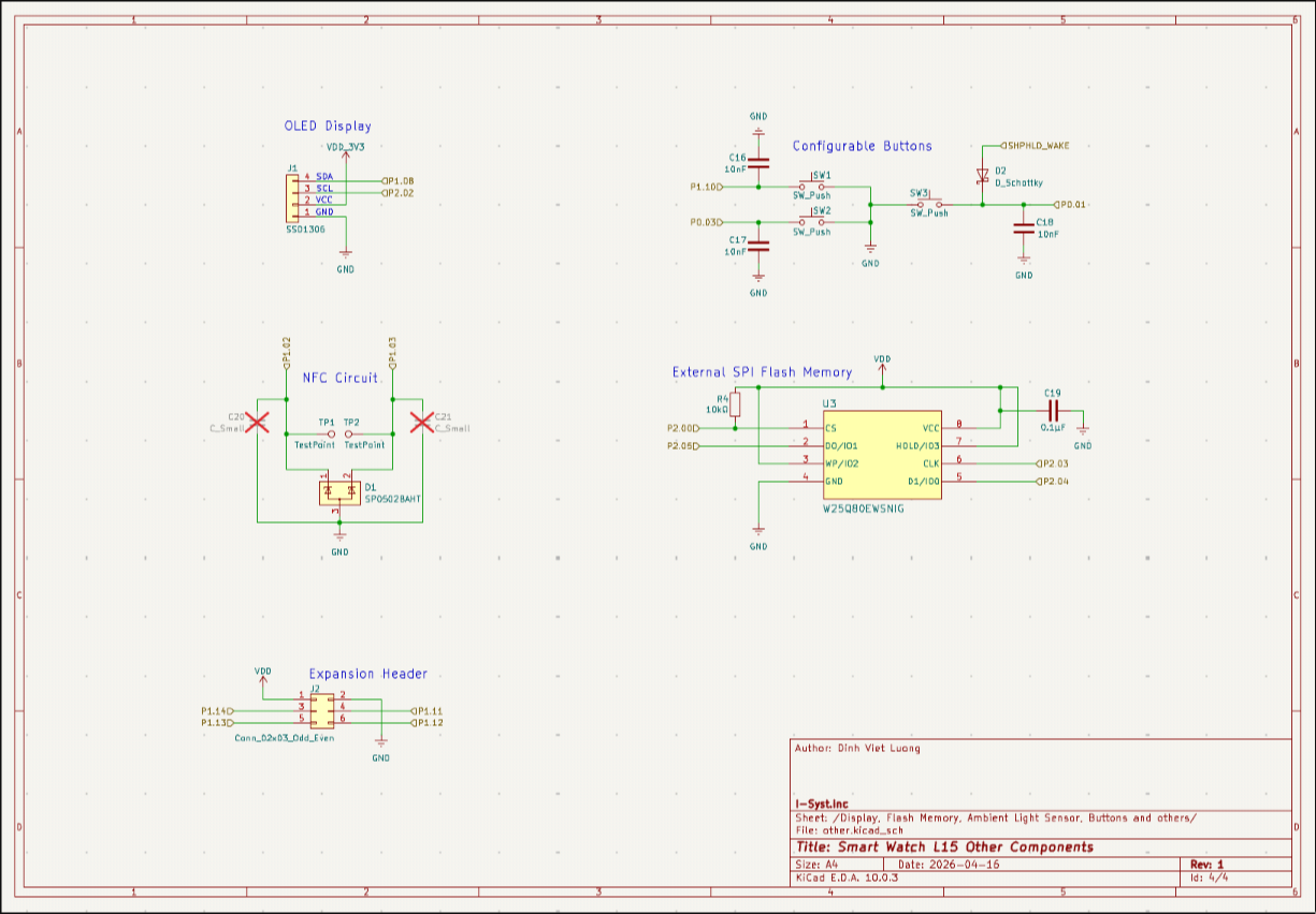 Fig 4: Flash memory, Configurable Buttons, OLED Connectors and Expansion Header
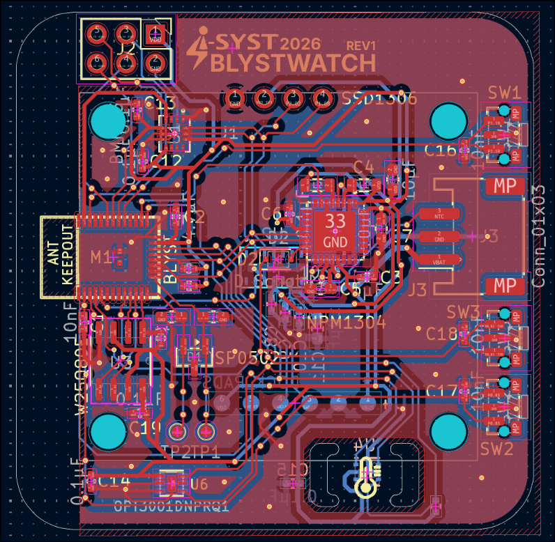 Fig 5: Top-down view of the routed PCB, showcasing the dense component placement and carefully voided QVAR keep-out zones.
Final physical visualization of the assembled board to be imported in SolidWorks for the design of the Watch's Case.
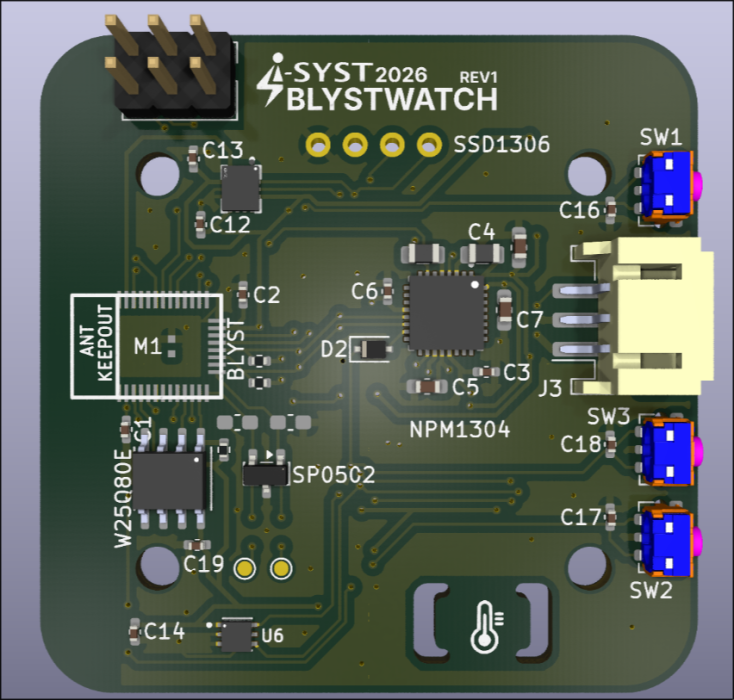
Fig 6: 3D Render (Top view) showing the sensor array and screen interface footprint.
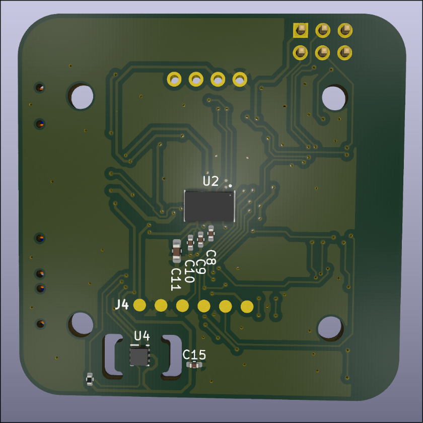
Fig 7: 3D Render (Bottom view) showing the BlystL15 module and exposed charging/programming test pads.
| Qty | Value | Footprint | References |
|---|---|---|---|
| 8 | 0.1μF | Capacitor_SMD:C_0402_1005Metric_Pad0.74x0.62mm_HandSolder | C6, C8, C9, C12, C13, C14, C15, C19 |
| 4 | 10nF | Capacitor_SMD:C_0402_1005Metric_Pad0.74x0.62mm_HandSolder | C1, C16, C17, C18 |
| 4 | 10μF | Capacitor_SMD:C_0603_1608Metric_Pad1.08x0.95mm_HandSolder | C4, C5, C7, C11 |
| 3 | SW_Push | Button_Switch_SMD:SW_Push_1P1T-MP_NO_Horizontal_Alps_SKRTLAE010 | SW1, SW2, SW3 |
| 2 | 1.0µH | Inductor_SMD:L_0805_2012Metric | L1, L2 |
| 2 | 4.7kΩ | Resistor_SMD:R_0402_1005Metric | R1, R2 |
| 2 | 4.7μF | Capacitor_SMD:C_0402_1005Metric_Pad0.74x0.62mm_HandSolder | C2, C10 |
| 2 | C_Small | Capacitor_SMD:C_0603_1608Metric_Pad1.08x0.95mm_HandSolder | C20, C21 |
| 2 | LOGO | LOGO | G***, G*** |
| 2 | TestPoint | TestPoint:TestPoint_Pad_D1.0mm | TP1, TP2 |
| 1 | 10kΩ | Resistor_SMD:R_0402_1005Metric | R4 |
| 1 | 1µF | Capacitor_SMD:C_0402_1005Metric_Pad0.74x0.62mm_HandSolder | C3 |
| 1 | 5kΩ | Resistor_SMD:R_0402_1005Metric | R3 |
| 1 | BLYST NANO/L15 | 1_I_Syst.inc:BLYSTL15 | M1 |
| 1 | BMI323 | 1_I_Syst.inc:LGA-14_L3.0-W2.5-P0.50-TL_QMI8658A | U1 |
| 1 | Conn_01x03 | Connector_JST:JST_PH_S3B-PH-SM4-TB_1x03-1MP_P2.00mm_Horizontal | J3 |
| 1 | Conn_02x03_Odd_Even | Connector_PinHeader_2.54mm:PinHeader_2x03_P2.54mm_Vertical | J2 |
| 1 | DOCK_PADS | 1_I_Syst.inc:Dock_Pads_6Pin | J4 |
| 1 | D_Schottky | Diode_SMD:D_SOD-323F | D2 |
| 1 | MAX30102EFD+T | 1_I_Syst.inc:21-1048_F143A5&plus_1_MXM-L | U2 |
| 1 | NPM1304 | 1_I_Syst.inc:QFN50P500X500X90-33N | U5 |
| 1 | OPT3001DNPRQ1 | 1_I_Syst.inc:SON65P200X200X65-7N | U6 |
| 1 | SP0502 | Package_TO_SOT_SMD:SOT-23 | D1 |
| 1 | SSD1306 | 1_I_Syst.inc:OLED_1.3in_I2C | J1 |
| 1 | TMP117AIDRVT | 1_I_Syst.inc:DRV0006B | U4 |
| 1 | W25Q80E | 1_I_Syst.inc:W25Q80EWSNIG_WIN-M | U3 |
DINDIN2007/Blystwatch
This is a demo board to showcase development with both the BlystL15 (based on the nrf54L15) and the IOComposer AI from I-Syst.inc.

CIRCUITSTATE/Mitayi-Pico-D1
Open-Source RP2040 Microcontroller Development Board


Fred98246/STM32-Environmental-Sensor-and-Datalogging-Board
An open-source STM32F103C8T6 development board designed for environmental monitoring, featuring integrated Li-Ion battery management, USB-C, MicroSD data logging, and onboard I2C sensors for temperature, humidity, and…

aidanaalund/sleep-wearable
Work on our sleep state tracker wearable headband for ECE Senior Design at UT Austin. Members are Aidan Aalund, Justin Banh, Alex Ho, and Kien Ton. Mentored by Dr. Edison Thomaz.


ponderononon/IEMU_DevBoards
Kicad Schematic Files for the BASE and SENSOR Development Boards (Layout in Progress)
It measures 45 × 45 mm and has 2 copper layers, 1.6 mm thick.
47 parts, built around the MAX30102EFD+T, OPT3001DNPRQ1, TMP117AIDRVR and W25Q80EWSNIG. The full list of its parts is on this page, with links to each part's symbol and footprint where PCBKit's library has them.
From the DINDIN2007/Blystwatch repository on GitHub, at the commit this page was made from: the board is Watch/Watch.kicad_pcb and its schematic Dock/Smart-Watch-L15-Dock.kicad_sch. PCBKit opens the board in the browser, with nothing to install.
Its repository states no licence, so its author keeps all rights: ask DINDIN2007 before reusing the design.