4 layers113.5 × 105.5 mm
Multistepper
eddyem/stm32samples
Code samples and ready projects based on bare-metal STM32
243 parts208
 Samuel20040521/SOC_Final
flico 是一台以 Raspberry Pi Pico 為核心、用於量測螢幕/光源閃爍 (flicker) 的小型自製儀器。光訊號由 Vishay BPW34 矽 PIN 光二極體接收,經 Microchip MCP6004 跨阻放大器 (TIA) 轉成電壓,由 Pico 的 ADC 取樣後,透過 USB-CDC 串列傳回桌面端的 Rust GUI 即時顯示時域波形與 FFT。
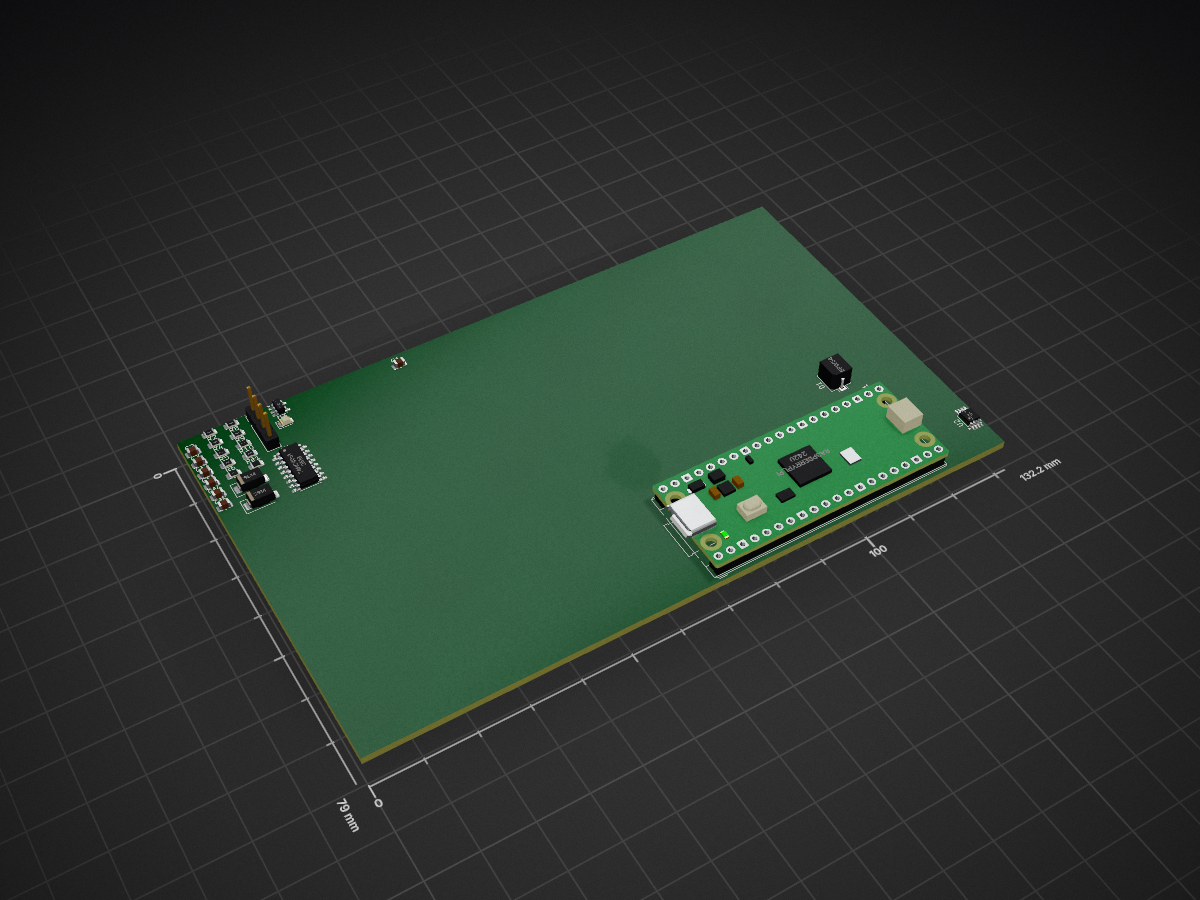
Pico flicker shield is an open-source printed circuit board by Samuel20040521, from the Samuel20040521/SOC_Final repository on GitHub. It is a 2-layer board with 26 parts on 45 nets.
It is built around the 74HC4051, SS14 and BPW34. Its parts include 10 resistors, 4 ICs, 4 diodes and 3 capacitors. It belongs with the RP2040 boards of this library.


flico = flicker + pico.
flico 是一台以 Raspberry Pi Pico 為核心、用於量測螢幕/光源閃爍 (flicker) 的小型自製儀器。光訊號由 Vishay BPW34 矽 PIN 光二極體接收,經 Microchip MCP6004 跨阻放大器 (TIA) 轉成電壓,由 Pico 的 ADC 取樣後,透過 USB-CDC 串列傳回桌面端的 Rust GUI 即時顯示時域波形與 FFT。
本 repo 是 flico 的整體專案資料夾,依照六種角色分組:
| 資料夾 | 角色 | 主要技術棧 |
|---|---|---|
firmware/ | 安裝在 Pico 內的 C++ 韌體 | Pico SDK (C/C++)、CMake、SSD1306 OLED 驅動 |
host/ | 安裝在電腦上、與 Pico 溝通的桌面 GUI | Rust、egui、eframe、序列埠;發行版 macOS / Windows |
hardware/main_board/ | TIA + Pico 主板的 PCB 設計 | KiCad 8、JLCPCB 製板封裝 |
hardware/shield/ | 主板的子板 / 連接板 | KiCad 8 |
mechanical/ | 整機 3D 列印外殼 | Fusion 360 Python API、.manifest 嵌入式腳本 |
simulation/ | TIA 電路的 PySpice 模擬與量測對照 | Python (uv)、PySpice、ngspice、SPICE 模型 |
report/ | 期末報告與研究日誌 | XeLaTeX (xeCJK + TW-Kai)、biblatex+biber |
各子資料夾各自獨立,互不耦合 — 看你想做什麼就進對應的資料夾。
firmware/)cd firmware/build && cmake .. && make
# 產出 firmware.uf2,拖到 Pico 的 RPI-RP2 磁碟即可燒錄host/)cd host && cargo run --releasesimulation/)cd simulation
uv sync # 安裝 Python 相依
uv run python main.py # DC sweep → figures/tia_sweep.png
uv run python ac_transient_sweep.py # AC + transient → figures/ac_bode.png, transient_pwm.png需要先有 libngspice0 (Linux) 或 ngspice (macOS Homebrew),詳見 simulation/report.md。
report/)cd report && xelatex main.tex && biber main && xelatex main.tex && xelatex main.tex
cd report/research-log && xelatex log.tex && biber log && xelatex log.tex && xelatex log.tex需要 TW-Kai (全字庫正楷體) 字型,可從 https://www.cns11643.gov.tw/opendata/Fonts_Kai.zip 取得。
電路拓樸、R_F / C_F 選擇邏輯、量測對照,請見 simulation/report.md。
| Qty | Value | Footprint | References |
|---|---|---|---|
| 3 | 100n | Capacitor_SMD:C_0805_2012Metric | C1, C2, C3 |
| 2 | 2k | Resistor_SMD:R_0805_2012Metric | R4, R10 |
| 2 | 4.7k | Resistor_SMD:R_0805_2012Metric | R6, Re1 |
| 2 | SS14 | Diode_SMD:D_SMA | D2, D4 |
| 1 | 1.8k | Resistor_SMD:R_0805_2012Metric | R2 |
| 1 | 100k | Resistor_SMD:R_0805_2012Metric | R8 |
| 1 | 10k | Resistor_SMD:R_0805_2012Metric | R7 |
| 1 | 1M | Resistor_SMD:R_0805_2012Metric | R9 |
| 1 | 1k | Resistor_SMD:R_0805_2012Metric | R5 |
| 1 | 1n | Capacitor_SMD:C_0805_2012Metric | Cf2 |
| 1 | 330p | Capacitor_SMD:C_0805_2012Metric | Cf3 |
| 1 | 33p | Capacitor_SMD:C_0805_2012Metric | Cf4 |
| 1 | 4.7p | Capacitor_SMD:C_0805_2012Metric | Cf5 |
| 1 | 56k | Resistor_SMD:R_0805_2012Metric | R1 |
| 1 | 74HC4051 | Package_SO:SOIC-16_3.9x9.9mm_P1.27mm | U4 |
| 1 | BPW34 | OptoDevice:Osram_DIL2_4.3x4.65mm_P5.08mm | D1 |
| 1 | Conn_01x04_Pin | Connector_PinHeader_2.54mm:PinHeader_1x04_P2.54mm_Vertical | OLED_Screen1 |
| 1 | LED | LED_SMD:LED_0805_2012Metric | D3 |
| 1 | MCP6002-xMC | Package_SO:MSOP-8_3x3mm_P0.65mm | U2 |
| 1 | MCP73831-2-OT | Package_TO_SOT_SMD:SOT-23-5 | U3 |
| 1 | RaspberryPi_Pico | Module:RaspberryPi_Pico_Common_THT | U1 |
eddyem/stm32samples
Code samples and ready projects based on bare-metal STM32

mcbronkowitch/fireflow
FireFlow — a modulation-first ambient groovebox: the modulation system is the instrument, not a layer on top of it. Five independent lanes per part driving a synth, granular, wavetable, resonator or bucket-brigade deck.

OA-Designs/LED-TILE
Modular decorative LED tiles in multiple shapes (hex, square, triangle...) sharing one PCB design. Tiles connect edge-to-edge to share power and sync lighting effects across a network.


QuantumVillage/UncutGem
A prototype Full Stack fully Open Source NV Center Diamond Magnetometer

RobertGawron/SemiconductorRadioactivityDetector
Nuclear radiation sensor with photodiode as a detector. Photodiode doesn't require high voltages as GM tubes do. Smaller size makes better resolution. Side effect is electronic must be more sensitive.

Roboy/HTC_Vive_Sensors
Schematics and PCB designs for our custom Vive sensors based on a quad op-amp chip rather than discrete transistors.
26 parts, built around the 74HC4051, SS14 and BPW34. The full list of its parts is on this page, with links to each part's symbol and footprint where PCBKit's library has them.
From the Samuel20040521/SOC_Final repository on GitHub, at the commit this page was made from: the board is hardware/shield/pico_flicker_shield/pico_flicker_shield.kicad_pcb and its schematic hardware/main_board/SOC_Final.kicad_sch. PCBKit opens the board in the browser, with nothing to install.
Its repository states no licence, so its author keeps all rights: ask Samuel20040521 before reusing the design.