2 layers256 × 121 mm
Forte PA Deck
SP6GK/Forte-600-HF-RF-Amplifier
Project of 600 W LDMOS amlifier based on 2xMRF300.
170 parts17GPL-3.0

 SP6GK/TXRX_Relay_Board2
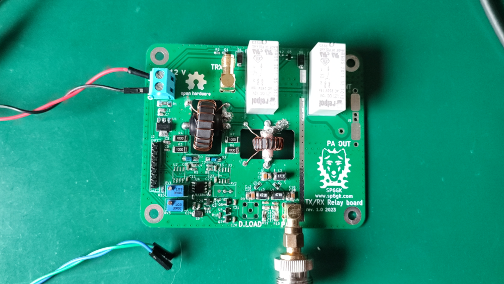
A PCB for switching the signal path between RX and TX in a high-power HF amplifier, such as the Forte 600. It includes RX/TX relays, an input SWR bridge, and analog input over power protection.
TXRX Relay Board is an open-source printed circuit board by SP6GK, from the SP6GK/TXRX_Relay_Board repository on GitHub, published under the GPL-3.0 licence. It is a 2-layer board of 100 × 82 mm with 80 parts on 45 nets, routed with 233 tracks and 450 vias.
It is built around the OP07, AMS1117-5.0 and BC807, with the RT314A05 and BC846 among its other parts. Its parts include 23 capacitors, 20 resistors, 8 diodes, 8 inductors and 6 transistors. It belongs with the home automation and IoT boards of this library.


A PCB for switching the signal path between RX and TX in a high-power HF amplifier, such as the Forte 600. It includes RX/TX relays, an input SWR bridge, and analog input over power protection.
For the theory of operation and functionality, please refer to section 2.2.1 of the Forte 600 documentation link.
| Qty | Value | Footprint | References |
|---|---|---|---|
| 12 | 100n | Capacitor_SMD:C_0603_1608Metric_Pad1.08x0.95mm_HandSolder | C1, C2, C6, C8, C9, C10, C15, C16, C17, C19, C21, C23 |
| 5 | 10k | Resistor_SMD:R_0603_1608Metric_Pad0.98x0.95mm_HandSolder | R1, R4, R7, R13, R20 |
| 5 | 1k | Resistor_SMD:R_0603_1608Metric_Pad0.98x0.95mm_HandSolder | R14, R16, R17, R18, R19 |
| 5 | BC807 | Package_TO_SOT_SMD:SOT-23 | Q1, Q2, Q4, Q5, Q6 |
| 4 | 100 | Resistor_SMD:R_2010_5025Metric_Pad1.40x2.65mm_HandSolder | R2, R3, R5, R6 |
| 3 | 100n | Capacitor_SMD:C_0805_2012Metric_Pad1.18x1.45mm_HandSolder | C4, C7, C13 |
| 3 | 1m | Inductor_SMD:L_1812_4532Metric_Pad1.30x3.40mm_HandSolder | L4, L6, L7 |
| 3 | 1u | Capacitor_SMD:C_0805_2012Metric_Pad1.18x1.45mm_HandSolder | C11, C12, C20 |
| 3 | 22n | Capacitor_SMD:C_0805_2012Metric_Pad1.18x1.45mm_HandSolder | C3, C5, C14 |
| 2 | 100 | Resistor_SMD:R_0603_1608Metric_Pad0.98x0.95mm_HandSolder | R8, R10 |
| 2 | 10u | Capacitor_SMD:C_0805_2012Metric_Pad1.18x1.45mm_HandSolder | C18, C22 |
| 2 | 1N4007 | Diode_SMD:D_SMA | D1, D8 |
| 2 | 510 | Resistor_SMD:R_1206_3216Metric_Pad1.30x1.75mm_HandSolder | R11, R12 |
| 2 | BAP64 | Diode_SMD:D_SOD-323_HandSoldering | D4, D5 |
| 2 | D_TVS | Diode_SMD:D_SOD-323 | D6, D7 |
| 2 | LOGO | logo | G***, G*** |
| 2 | L_Ferrite_Coupled | TXRX_rel_lib:FT82_trafo | L1, L2 |
| 2 | L_Small | Inductor_SMD:L_0603_1608Metric_Pad1.05x0.95mm_HandSolder | L3, L5 |
| 2 | RT314A05 | Relay_THT:Relay_SPDT_Schrack-RT1-16A-FormC_RM5mm | K1, K2 |
| 2 | Schottky | Diode_SMD:D_SMA | D2, D3 |
| 1 | 10 | Resistor_SMD:R_2010_5025Metric_Pad1.40x2.65mm_HandSolder | R15 |
| 1 | 100u | Capacitor_SMD:C_1206_3216Metric_Pad1.33x1.80mm_HandSolder | L8 |
| 1 | 10k | Potentiometer_THT:Potentiometer_Bourns_3296W_Vertical | RV1 |
| 1 | 50 | Connector_Coaxial:SMA_Amphenol_901-144_Vertical | R9 |
| 1 | AMS1117-5.0 | Package_TO_SOT_SMD:SOT-223-3_TabPin2 | U2 |
| 1 | BC846 | Package_TO_SOT_SMD:SOT-23 | Q3 |
| 1 | Conn_01x08 | Connector_JST:JST_EH_B8B-EH-A_1x08_P2.50mm_Vertical | J2 |
| 1 | IN | Connector_Coaxial:SMA_Amphenol_901-144_Vertical | J3 |
| 1 | IN_RF_Deck | Connector_Coaxial:SMA_Amphenol_901-144_Vertical | J4 |
| 1 | OP07 | Package_SO:SOIC-8_3.9x4.9mm_P1.27mm | U1 |
| 1 | OUT | TXRX_rel_lib:Coax_solder | J6 |
| 1 | OUT_RF_Deck | TXRX_rel_lib:Coax_solder | J5 |
| 1 | Screw_Terminal_01x02 | TerminalBlock:TerminalBlock_bornier-2_P5.08mm | J1 |
The 78 most common of 80 parts.
SP6GK/Forte-600-HF-RF-Amplifier
Project of 600 W LDMOS amlifier based on 2xMRF300.


wszeto9/2_679_PCB
PCB Project for 2.679 which is then used in my 2.007 Competition Robot

adeboni/eurorack
This repository stores various eurorack module designs I've made


danielsimonreinhardt/microHIL
microHIL is a self-developed testing device for setting up a basic hardware-in-the-loop environment


practable/truss
The truss remote laboratory has been designed for use with Structural Engineering and Engineering Design courses at the University of Edinburgh.
It measures 100 × 82 mm and has 2 copper layers, 1.6 mm thick.
80 parts, built around the OP07, AMS1117-5.0, BC807 and RT314A05. The full list of its parts is on this page, with links to each part's symbol and footprint where PCBKit's library has them.
From the SP6GK/TXRX_Relay_Board repository on GitHub, at the commit this page was made from: the board is TXRX_relay_board.kicad_pcb and its schematic TXRX_relay_board.kicad_sch. PCBKit opens the board in the browser, with nothing to install.
Its repository publishes it under the GPL-3.0 licence: you may reuse it on that licence's terms (keep the author's notice, and for a copyleft licence share your changes alike).