2 layers71.8 × 24.9 mm
PowerBoard
quezadaminter/CR101kc
The electrical schematics and PCB layout for the CR101 boards.
23 partsMIT
 SIMATICmeetsLinux/IOT2050-LoRaGateway-Arduino5
Instructions for using the IOT2050 as a LoRaWAN (Long Range Wide Area Nework) gateway with The Things Network as the network server. LoRaWAN Concentrator is realized with an Arduino Shield.
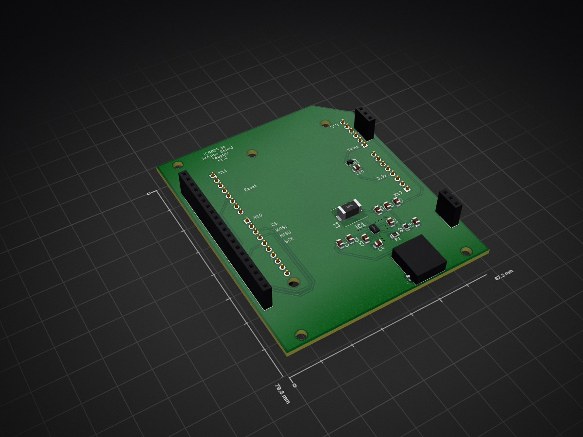
IC880A shield v1.2 is an open-source printed circuit board by SIMATICmeetsLinux, from the SIMATICmeetsLinux/IOT2050-LoRaGateway-Arduino repository on GitHub, published under the MIT licence. It is a 2-layer board of 67.2 × 79.8 mm with 29 parts on 60 nets, routed with 81 tracks and 12 vias.
It is built around the LMR36015ARNXT and PJ-079AH. Its parts include 10 capacitors, 8 connectors, 2 resistors, 2 ICs and 1 inductor. It belongs with the radio and wireless and computers and single-board computers boards of this library.

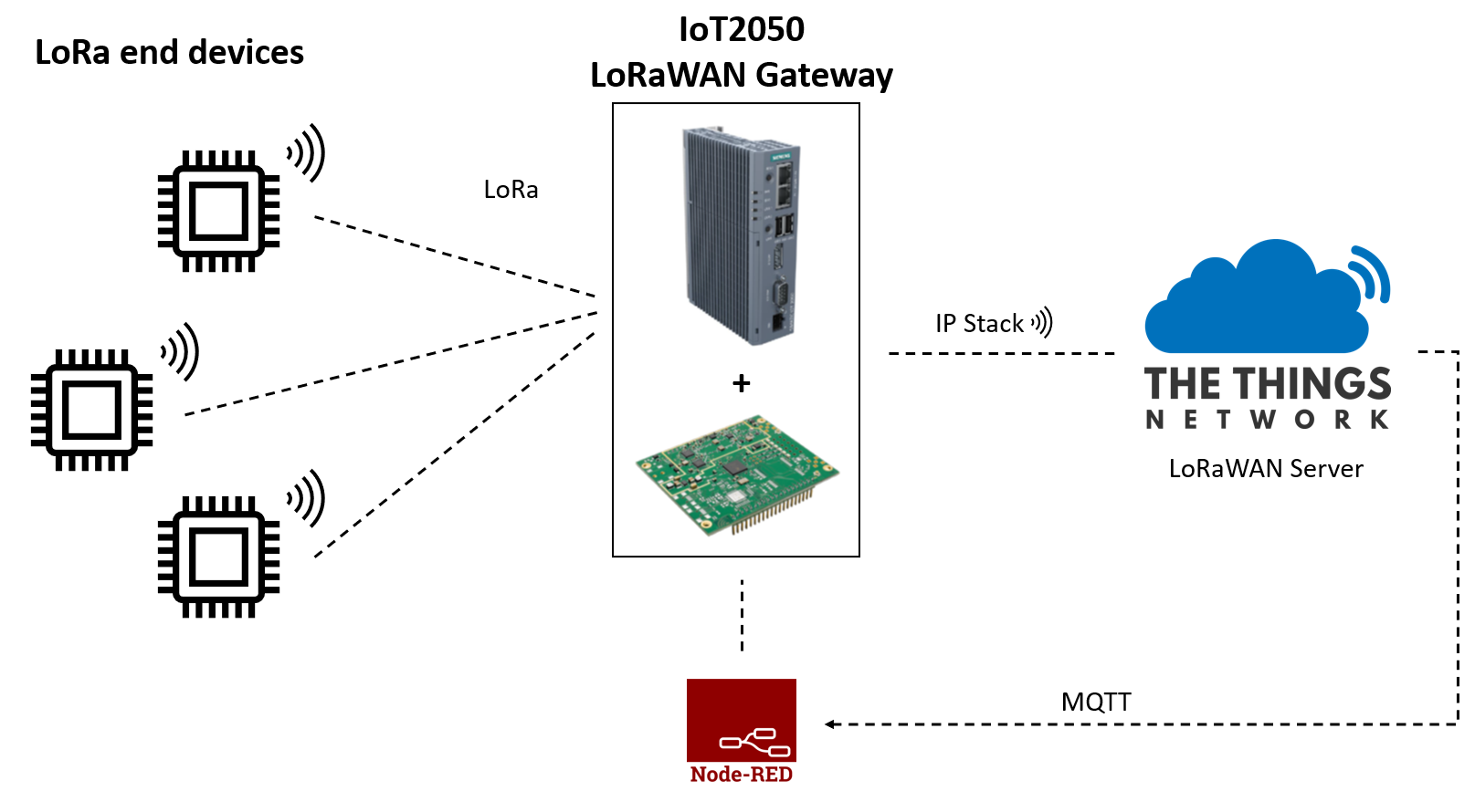
This IOT2050 application has the task of collecting data decentralized and transmitting it via radio. The LPWAN technology Long Range (LoRa) is used for this purpose. The IOT2050 serves as a LoRaWAN Gateway. The global, free LoRaWAN (Long Range Wide Area Network) from The Things Network or The Things Stack Community Edition is used as the network server. This manual describes the software and hardware structure of the gateway (the configuration and function of end devices (e.g sensors) is not explained in this manual, because it depends on the individual purpose of the application):
The following hardware components are required for the application:
You can also see all individual parts in the order list.
The Arduino Uno Interface of the SIMATIC IOT2050 is used to integrate the iC880A Concentrator. An adapter shield is required for this purpose, which combines the pin assignments. The concentrator is supplied with 5V.
The adapter shield used in this application was self-built. The required components can be taken from the order list. Further information about the structure can be found in the project file (.pro), the schematic file (.sch) and the layout file (.kicad_pcb).
The LoRaWAN Concentrator iC880A is a multi-channel high performance transmitter/receiver module designed to receive several LoRa packets simultaneously using different spreading factors on multiple channels. The concentrator module iC880A can be integrated into a gateway as a complete RF front end of this gateway.
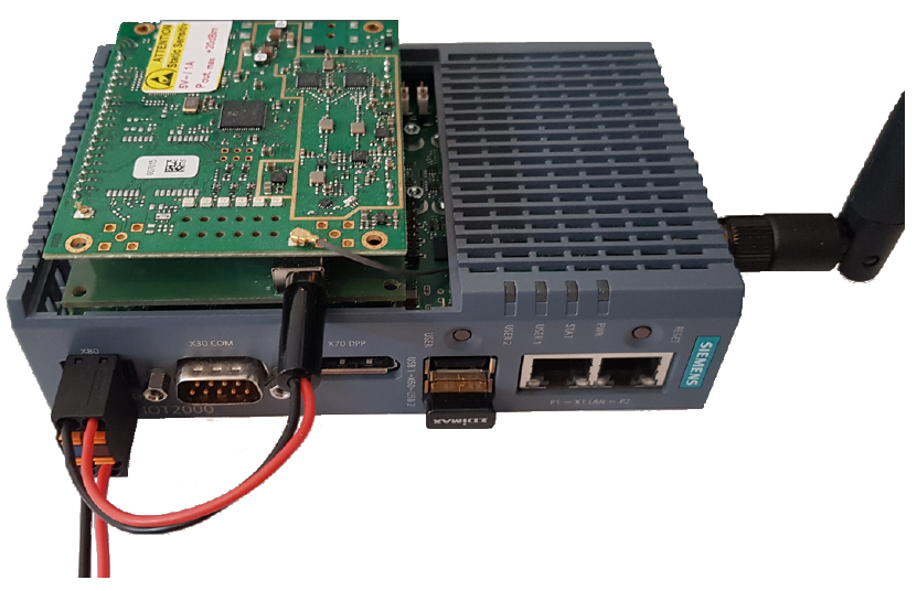
The following figure shows the complete hardware structure of the LoRaWAN gateway. To connect the antenna (2 dBi Dipole Antenna 863-870MHz with RP SMA) to the iC880A module, a U.FL to reverse SMA adapter is used. The concentrator is plugged into the Arduino Uno interface of the IOT2050 together with the adapter shield.
The following software is used for this manual:
For the first commissioning of the IOT2050 please refer to the Setting Up. You can get further help in the SIMATIC IOT2050 forum.
After working through the Setting Up, an update must be performed for the system and git must be installed. The following commands are executed for this:
sudo apt-get update
sudo apt-get install gitEstablish a shh connection via putty and use the following commands:
iot2050setup
Use the arrow keys: "Peripherals" -> "Configure Arduino I/O" -> "Enable SPI on IO10-IO13" -> "Enable"
Use ESC to exit the iot2050setup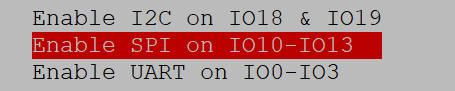
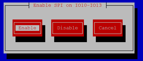
To clone the latest version of LoRa Basics™ Station from Github use the following commands:
cd /home
git clone https://github.com/lorabasics/basicstation.gitNow the setup.gmk file, which is part of the clone, must be adapted for the IOT2050 to store the correct directories for the toolchain. To do this, open the file in an editor using the following commands:
cd /home/basicstation/
nano setup.gmk
With the key combination CTRL+C a line specification can be shown in the nano-editor:

Lines 55 - 66 must be commented out with # and lines 68 - 72 must be changed to the following:
CC=/usr/bin/gcc
LD=/usr/bin/ld
AR=/usr/bin/ar
OD=/usr/bin/objdump
OC=/usr/bin/objcopy
In addition, line 76 must be edited as follows:
export LD_LIBRARY_PATH=/usr/local/libSave and close the file with the following commands:
CTRL+X -> to exit editing
Y -> to save the changes
Enter -> to confirm the filenameTo build the package forwarder station use the following command in the directory /home/basicstation/:
make platform=rpi variant=stdAfter the Basic Station has been compiled, a new folder called build-rpi-std with four subfolders has appeared. You can find the compiled binary station in the subfolder bin.
Unless otherwise specified, the following commands and actions are always executed in this directory (/home/basicstation/build-rpi-std/bin/).
Some configurations are needed for the Basic Station, which are specified in the file station.conf. Copy the ready-made file station.conf into the directory (Tip: The tool WINSCP can be used to transfer the files).
The LoRa Basics™ Station needs to be provided with the LoRaWAN® Network Server (LNS) to connect to. For this example The Things Stack Community Edition server with port 8887 is used. This is specified in the file tc.uri. Copy the ready-made file tc.uri into the directory.
This requires a root certificate. The following command can be used to get a certificate and create the file tc.trust directly:
curl https://letsencrypt.org/certs/isrgrootx1.pem.txt -o tc.trustYou can also use another root certificate, which needs to be inserted into the tc.trust file without the characters <>:
-----BEGIN CERTIFICATE-----
<insert root certificate here>
-----END CERTIFICATE-----The iC880A module with the SX1301 baseband chip must be reset every time it is switched on. However, this reset is not performed by the HAL of the chip. Therefor a Python script is written to carry that out externally. Copy the Python script iC880A_Reset.py into the directory. Afterwards the Digital I/O PIN 4 must be set as output, because this is used as reset pin:
iot2050setup
Use the arrow keys: "Peripherals" -> "Configure Arduino I/O" -> "Enable GPIO" -> Set PIN 4 as output
Use ESC to exit the iot2050setup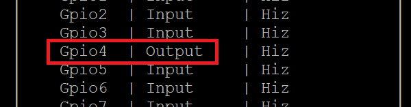
The next step is to add a shell script that executes the Python script. This script will later be executed with the start of the station binary. Copy the ready-made file reset_gw.sh into the directory. In this shell script, the previously created Python script for the hardware reset of the concentrator is called. The script needs now to be provided with executable rights with the following command:
chmod 755 reset_gw.shTo get the EUI of the gateway for registration at the server, the program station needs to be started once (execution is not fully functional yet):
./stationThe EUI of the gateway is composed of the MAC address of the IOT2050 and is displayed in the console output after the station has been started:

The application can be stopped with the key combination CTRL+C.
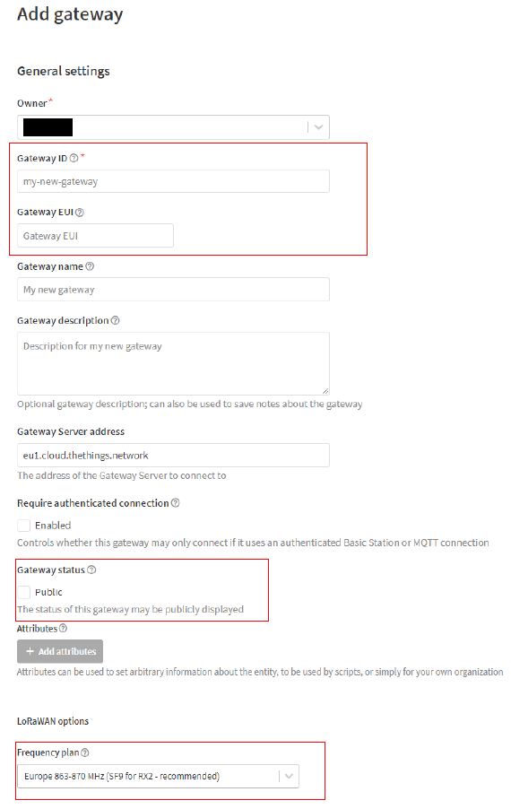
Finally, to authorize the gateway with The Things Stack Community Edition, an API key must be stored in a file called tc.key. To do this, the gateway must be registered at The Things Stack Community Edition. This is explained in the following steps: After logging into the webpage, the region is selected. After that a new gateway can be added. For this, a unique gateway ID must be entered, as well as the gateway EUI from the previous figure. In addition, the frequency plan for the region is selected. Furthermore, it can be selected whether the status of the gateway is publicly visible. All required configurations are shown in the following figure:
After registering the new gateway, an API Key must be generated for authorization. Before the key is generated, it is assigned a name. In addition, it is given individual rights for linking as a gateway with a gateway server for data exchange. After the creation of the API key it must be copied and stored urgently, because it is encrypted afterwards and therefore no longer visible.
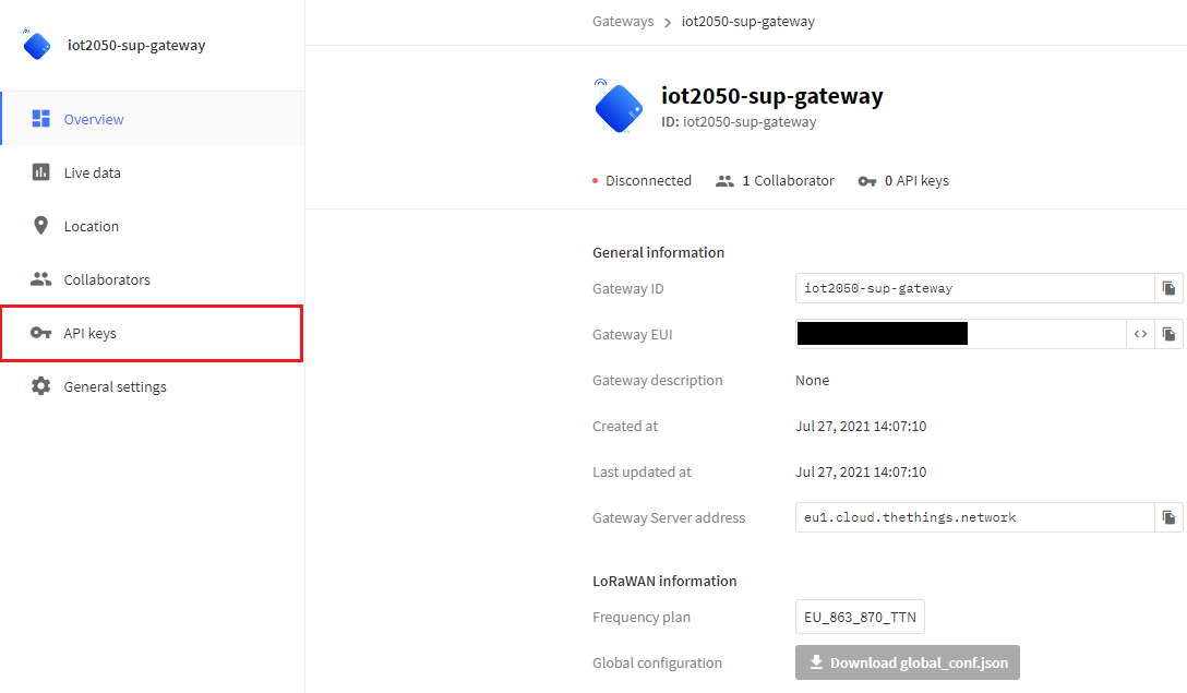
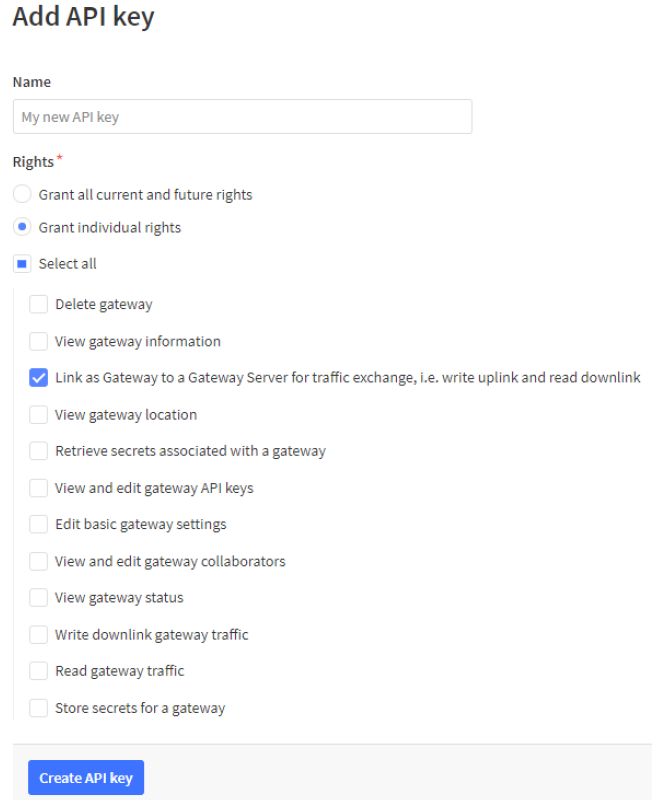
Use the following commands to build the tc.key file and use the previously copied API key instead of xxx:
export LNS_KEY="xxx"
echo "Authorization: Bearer $LNS_KEY" | perl -p -e 's/\r\n|\n|\r/\r\n/g' > tc.key
This completes the installation and configuration of the Basic Station. Now the the station can be started manually with the command:
./stationIf the installation and authentication are successful, the station starts and the gateway is displayed as connected in the console of The Things Stack Community Edition:

You can receive further information on the The Things Stack Website - Adding Gateways.
Copy the ready-made shell script start.sh, which call the station binary, into the directory. The script must then be provided with executable rights:
chmod 755 start.shCopy the ready-made systemd service file iot-2050-lora-gateway.service into the directory /etc/systemd/system. To change to that directory use the following command:
cd /etc/systemd/systemThe service file can now be started manually and tested with the following command:
sudo systemctl start iot2050-lora-gateway.serviceAfter successful start of the service and the station, it can be terminated with the following command:
sudo systemctl stop iot2050-lora-gateway.serviceTo enable the autostart of the service use the command
sudo systemctl enable iot2050-lora-gateway.serviceAfter the next reboot, the gateway will be started with every boot.
The gateway is now ready for use. End devices can now be added to the application via The Things Stack Community Edition, which then transmit data via the gateway to the server. Here you can find some possible end devices. How to add end devices on the server is described here
Node-Red is used to visualize the collected data. The web editor is accessible via the IP address of the IOT2050 and port 1880. Node-red is in autostart by default on the Example Image. To access it, open a browser on your PC connected to the IOT2050 and open the URL http://<IP of the IOT2050>:1880/.
Now the flows.json file can be imported into Node-Red:
Menu -> Import -> Select file for Upload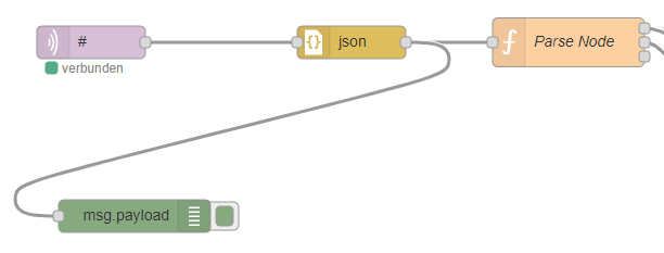
The nodes must be adjusted as follows:
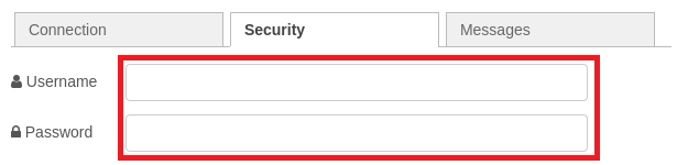
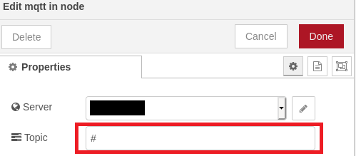
MQTT: Insert the server address and the port of The Things Stack in the connection tab. To subscribe all messages set Topic to #.

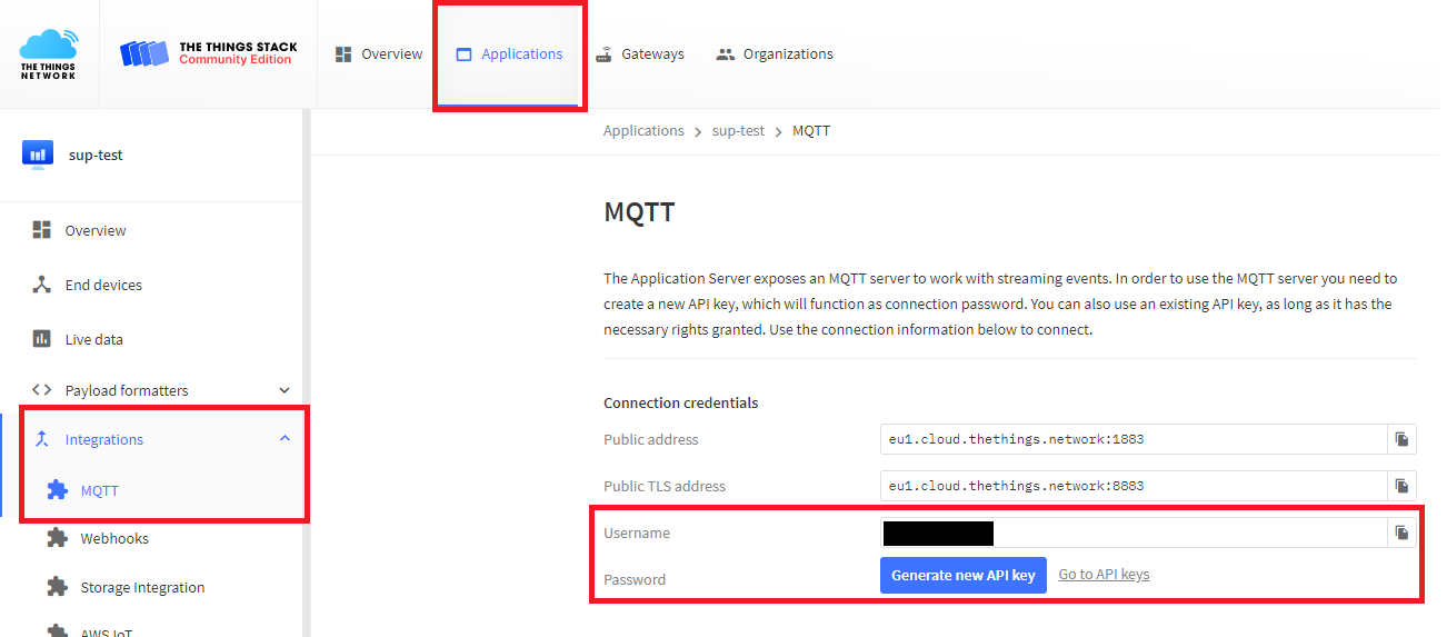
Enter your Username and the MQTT-API-Key as the Password. You can generate this API-Key in the integrations-settings of your application:
Parse Node: In the function Parse Node the different device_id must be adjusted (depending on the application):
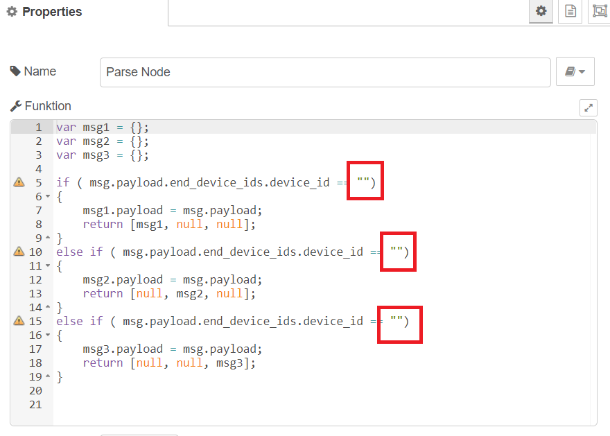
Description of the flow: To process the incoming messages, a Javascript object is created first. Then the uplinks are parsed in the function Parse Node to extract the individual messages of each end device. In addition, the node is extended to three outputs. Thus, each message is assigned to an output and stands for an end device. Using the dashboard library and the gauge node, these can then be individually built into a dashboard.
The pre-build flow shows an example of the combination of three end devices in the parse node. The ID's must be adjusted depending on the application and the setting in The Things Network.
Dashboard: To display the data, the Dashboard palette can now be installed and individually configured:
Menu -> Manage Palette -> Install Tab -> Search and install the given librariesCompletion: To download the flow to the IOT2050 click on the button Deploy
To open the dashboard of node-red open the URL http://<IP of the IOT2050>:1880/ui
Thank you for your interest in contributing. Anybody is free to report bugs, unclear documentation, and other problems regarding this repository in the Issues section. Additionally everybody is free to propose any changes to this repository using Pull Requests.
If you haven't previously signed the Siemens Contributor License Agreement (CLA), the system will automatically prompt you to do so when you submit your Pull Request. This can be conveniently done through the CLA Assistant's online platform. Once the CLA is signed, your Pull Request will automatically be cleared and made ready for merging if all other test stages succeed.
Please read the Legal information.
| Qty | Value | Footprint | References |
|---|---|---|---|
| 3 | 22uF | Capacitor_SMD:C_0805_2012Metric | C7, C8, C9 |
| 3 | MountingHole | MountingHole:MountingHole_3mm | H1, H2, H3 |
| 3 | MountingHole | MountingHole:MountingHole_3.2mm_M3 | H4, H5, H6 |
| 2 | 100nF | Capacitor_SMD:C_0805_2012Metric | C5, C10 |
| 2 | 220nF | Capacitor_SMD:C_0805_2012Metric | C2, C3 |
| 2 | Conn_01x03_Female | Connector_PinSocket_2.54mm:PinSocket_1x03_P2.54mm_Vertical | J2, J3 |
| 2 | Conn_01x08_Male | Connector_PinHeader_2.54mm:PinHeader_1x08_P2.54mm_Vertical | J6, J8 |
| 1 | 100k | Resistor_SMD:R_0805_2012Metric | R2 |
| 1 | 10uH | WE-PD_7332:WE-PD_7332_7345_PLASTIC_BASE54 | L1 |
| 1 | 1uF | Capacitor_SMD:C_0805_2012Metric | C4 |
| 1 | 20pF | Capacitor_SMD:C_0805_2012Metric | C6 |
| 1 | 24.9k | Resistor_SMD:R_0805_2012Metric | R1 |
| 1 | 4.7uF | Capacitor_SMD:C_0805_2012Metric | C1 |
| 1 | Conn_01x06_Male | Connector_PinHeader_2.54mm:PinHeader_1x06_P2.54mm_Vertical | J7 |
| 1 | Conn_01x10_Male | Connector_PinHeader_2.54mm:PinHeader_1x10_P2.54mm_Vertical | J5 |
| 1 | Conn_01x20_Female | Connector_PinSocket_2.54mm:PinSocket_1x20_P2.54mm_Vertical | J4 |
| 1 | LMR36015ARNXT | LMR36015:LMR36015FSCQRNXTQ1 | IC1 |
| 1 | MCP9700AT-ELT | Package_TO_SOT_SMD:SOT-353_SC-70-5 | IC2 |
| 1 | PJ-079AH | pj-079ah:CUI_PJ-079AH | J1 |
quezadaminter/CR101kc
The electrical schematics and PCB layout for the CR101 boards.

gusmanb/logicanalyzer
24 channel, 100Msps logic analyzer hardware and software

VoronDesign/Voron-Hardware
Cool Hardware designed by the Voron Design group

hoglet67/RGBtoHDMI
Bare-metal Raspberry Pi project that provides pixel-perfect sampling of Retro Computer RGB/YUV video and conversion to HDMI

hackclub/OnBoard
💡 Join 1,000 teenagers and make your first PCB with a $100 grant!

OLIMEX/DIY-LAPTOP
Do It Yourself Open Source Hardware and Software Modular Hacker's Friendly Laptop

UtilitechAS/amsreader-firmware
ESP8266 and ESP32 compatible firmware to read, interpret and publish data to MQTT from smart electrical meters, both DLMS and DSMR is supported

It measures 67.2 × 79.8 mm and has 2 copper layers, 1.6 mm thick.
29 parts, built around the LMR36015ARNXT and PJ-079AH. The full list of its parts is on this page, with links to each part's symbol and footprint where PCBKit's library has them.
From the SIMATICmeetsLinux/IOT2050-LoRaGateway-Arduino repository on GitHub, at the commit this page was made from: the board is docs/adapter shield/iC880A_shield_v1.2.kicad_pcb. PCBKit opens the board in the browser, with nothing to install.
Its repository publishes it under the MIT licence: you may reuse it on that licence's terms (keep the author's notice, and for a copyleft licence share your changes alike).