2 layers100 × 100 mm
Neuromorphic ir sensor tht
RyanHailey21/neuromorphic-IR-hand-assembled
All through-hole re-implementation of the Rev A neuromorphic IR event sensor: no SMD parts, solderable with a basic iron.
102 parts

 RyanHailey21/neuromorphic-IR-hand-assembled
All through-hole re-implementation of the Rev A neuromorphic IR event sensor: no SMD parts, solderable with a basic iron.
Neuromorphic ir sensor compact is an open-source printed circuit board by RyanHailey21, from the RyanHailey21/neuromorphic-IR-hand-assembled repository on GitHub. It is a 4-layer board of 30 × 30 mm with 121 parts on 62 nets, routed with 1,301 tracks and 212 vias.
It is built around the SN74LVC1G123DCUR, BLM15AG601SN1D11 and AO3400A, with the TSAL6200 among its other parts. Its parts include 38 capacitors, 35 resistors, 15 ICs, 5 diodes and 1 transistor. It belongs with the sensors and measurement boards and the FPGA and CPLD boards of this library.


All through-hole re-implementation of the Rev A neuromorphic IR event sensor: no SMD parts, solderable with a basic iron. Same architecture as the SMD design spec: 4 photodiodes → TIA → temporal adaptation → ON/OFF comparators → one-shots → 8 asynchronous 3.3 V spike outputs for the Tang Nano 20K.
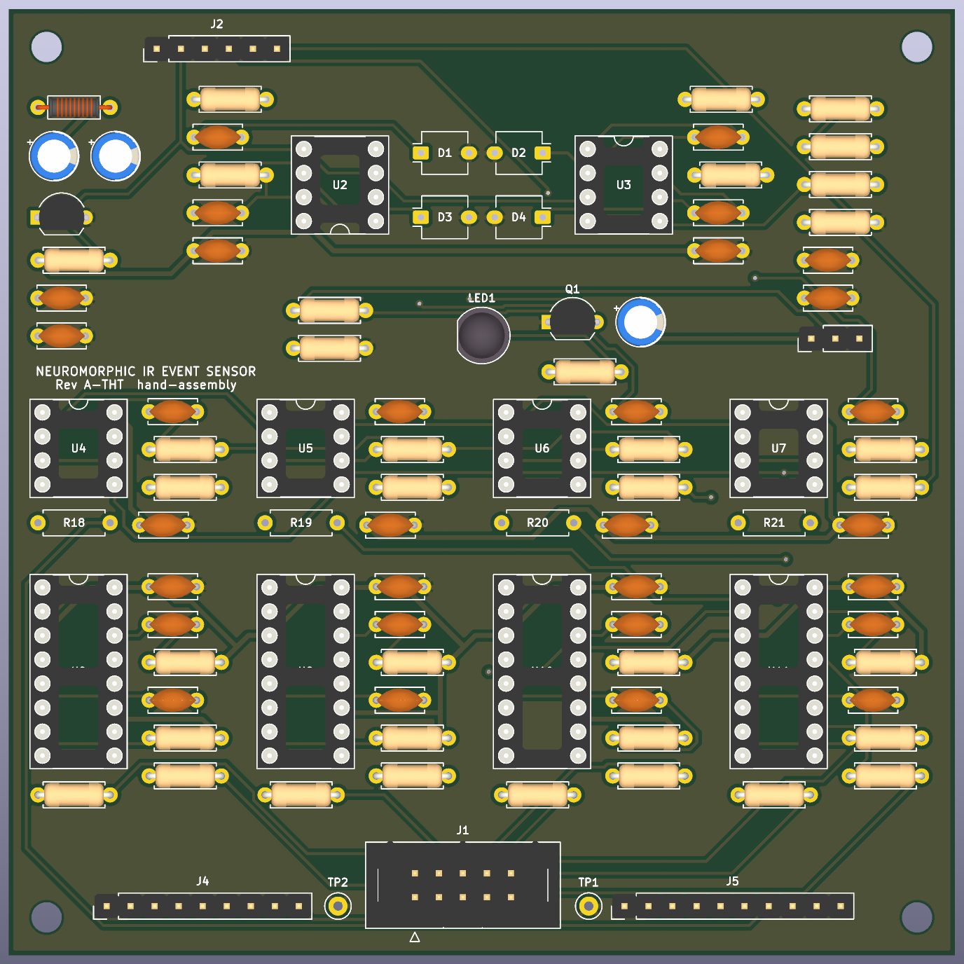
production/neuromorphic-ir-sensor-tht-revA-THT-gerbers.zip (upload as-is to JLCPCB/PCBWay, bare board only)production/neuromorphic-ir-sensor-tht-BOM.csv · Schematic: docs/schematic.pdf · Assembly drawing: docs/assembly_top.pdf| Function | SMD Rev A | Rev A-THT | Effect |
|---|---|---|---|
| TIA ×4 | OPA381 | 2× MCP6022-I/P (dual, DIP-8) | RF/CF unchanged (18k / 47 pF); ~188 kHz BW, large phase margin |
| Comparators ×8 | 4× TLV3202 | 4× MCP6542-I/P (dual, DIP-8) | ~4 µs response, irrelevant vs 2.2 ms adaptation |
| One-shots ×8 | 8× 74LVC1G123 | 4× 74HC123 (dual, DIP-16) | 18k / 12 nF ≈ 100 µs (K≈0.45) — tune on bench |
| VREF | REF3312 1.250 V | LM385BZ-1.2 1.235 V + 4.7k | Thresholds ≈ +40.6 / −39.7 mV |
| LED switch | AO3400A | PN2222A + 1k base | ~22 mA LED current with 82 Ω |
| Photodiodes | VBPW34FASR | OSRAM BPW 34 F (daylight filter) | Same die, THT |
The FPGA connector follows the spec (keyed 2×5: GND, 3V3, SPIKE_ON/OFF × 4). The AER / 2×10 pinout in the old README had no driving circuitry and was dropped.
| Ref | Pins |
|---|---|
| J1 FPGA (2×5 box) | 1 GND · 2 3V3 · 3 ON_TL · 4 OFF_TL · 5 ON_TR · 6 OFF_TR · 7 ON_BL · 8 OFF_BL · 9 ON_BR · 10 OFF_BR |
| J2 DEBUG | 1 GND · 2 VREF · 3–6 VPHOTO_TL/TR/BL/BR (via 100 Ω) |
| J3 LED_EN | 1 3V3 · 2 LED_EN · 3 GND — jumper 1-2 = LED on, 2-3 = off, or drive pin 2 from FPGA |
| J4 RAW_PROBE | 1 GND · 2–9 RAW_ON/OFF_TL, TR, BL, BR |
| J5 EVENT_PROBE | 1 GND · 2 3V3 · 3 3V3A · 4 VREF · 5 VTH_ON · 6 VTH_OFF · 7–10 VEVENT_TL/TR/BL/BR |
Everything is generated from .companion/scripts/design.py (netlist source of truth). With KiCad closed:
python .companion/scripts/gen_schematic.py --force
"C:/Program Files/KiCad/10.0/bin/python.exe" .companion/scripts/gen_pcb.py --force
python .companion/scripts/setup_rules.py
# autoroute (kicad-companion autoroute_board / Freerouting), then:
"C:/Program Files/KiCad/10.0/bin/python.exe" .companion/scripts/finalize_pcb.py
python .companion/scripts/setup_rules.py
Close KiCad before regenerating: it rewrites the .kicad_pro from memory on exit and drops the net classes.
| Qty | Value | Footprint | References |
|---|---|---|---|
| 22 | 100nF | Capacitor_SMD:C_0201_0603Metric | C3, C11, C13, C15, C17, C18, C19, C20, C21, C22, C24, C26, C28, C30, C32, C34 +6 |
| 9 | 100k | Resistor_SMD:R_0201_0603Metric | R17, R19, R21, R23, R25, R27, R29, R31, R35 |
| 8 | 150 | Resistor_SMD:R_0201_0603Metric | R18, R20, R22, R24, R26, R28, R30, R32 |
| 8 | 1nF | Capacitor_SMD:C_0201_0603Metric | C23, C25, C27, C29, C31, C33, C35, C37 |
| 8 | SN74LVC1G123DCUR | Package_SO:VSSOP-8_2.3x2mm_P0.5mm | U8, U9, U10, U11, U12, U13, U14, U15 |
| 4 | 18k 0.1% | Resistor_SMD:R_0201_0603Metric | R5, R7, R9, R11 |
| 4 | 1M | Resistor_SMD:R_0201_0603Metric | R13, R14, R15, R16 |
| 4 | 22k | Resistor_SMD:R_0201_0603Metric | R6, R8, R10, R12 |
| 4 | 47pF | Capacitor_SMD:C_0201_0603Metric | C10, C12, C14, C16 |
| 4 | BPW 34 FAS | OptoDevice:Osram_BPW34S-SMD | D1, D2, D3, D4 |
| 4 | TLV3202AIDGKR | Package_SO:VSSOP-8_3x3mm_P0.65mm | U4, U5, U6, U7 |
| 3 | 10uF | Capacitor_SMD:C_0402_1005Metric | C1, C2, C38 |
| 2 | 10k 0.1% | Resistor_SMD:R_0402_1005Metric | R2, R3 |
| 2 | M2 | MountingHole:MountingHole_2.2mm_M2 | H1, H2 |
| 2 | OPA2381AIDRBR | Package_SON:VSON-8-1EP_3x3mm_P0.65mm_EP1.65x2.4mm | U2, U3 |
| 1 | 100 | Resistor_SMD:R_0201_0603Metric | R34 |
| 1 | 1uF | Capacitor_SMD:C_0201_0603Metric | C4 |
| 1 | 301k 0.1% | Resistor_SMD:R_0402_1005Metric | R4 |
| 1 | 3V3A | TestPoint:TestPoint_Pad_D1.0mm | TP1 |
| 1 | 499k 0.1% | Resistor_SMD:R_0402_1005Metric | R1 |
| 1 | 600R@100MHz | Inductor_SMD:L_0402_1005Metric | FB1 |
| 1 | 82 | Resistor_SMD:R_0402_1005Metric | R33 |
| 1 | AO3400A | Package_TO_SOT_SMD:SOT-23 | Q1 |
| 1 | FPGA | Connector_PinHeader_1.27mm:PinHeader_2x05_P1.27mm_Vertical_SMD | J1 |
| 1 | GND | TestPoint:TestPoint_Pad_D1.0mm | TP2 |
| 1 | LED_EN | Jumper:SolderJumper-3_P1.3mm_Bridged12_Pad1.0x1.5mm | JP1 |
| 1 | LED_EN | TestPoint:TestPoint_Pad_D1.0mm | TP6 |
| 1 | RAW_OFF_BL | TestPoint:TestPoint_Pad_D1.0mm | TP20 |
| 1 | RAW_OFF_BR | TestPoint:TestPoint_Pad_D1.0mm | TP22 |
| 1 | RAW_OFF_TL | TestPoint:TestPoint_Pad_D1.0mm | TP16 |
| 1 | RAW_OFF_TR | TestPoint:TestPoint_Pad_D1.0mm | TP18 |
| 1 | RAW_ON_BL | TestPoint:TestPoint_Pad_D1.0mm | TP19 |
| 1 | RAW_ON_BR | TestPoint:TestPoint_Pad_D1.0mm | TP21 |
| 1 | RAW_ON_TL | TestPoint:TestPoint_Pad_D1.0mm | TP15 |
| 1 | RAW_ON_TR | TestPoint:TestPoint_Pad_D1.0mm | TP17 |
| 1 | REF3312AIDCKR | Package_TO_SOT_SMD:SOT-323_SC-70 | U1 |
| 1 | TSAL6200 | LED_THT:LED_D5.0mm_IRGrey | LED1 |
| 1 | VEVENT_BL | TestPoint:TestPoint_Pad_D1.0mm | TP13 |
| 1 | VEVENT_BR | TestPoint:TestPoint_Pad_D1.0mm | TP14 |
| 1 | VEVENT_TL | TestPoint:TestPoint_Pad_D1.0mm | TP11 |
| 1 | VEVENT_TR | TestPoint:TestPoint_Pad_D1.0mm | TP12 |
| 1 | VPHOTO_BL | TestPoint:TestPoint_Pad_D1.0mm | TP9 |
| 1 | VPHOTO_BR | TestPoint:TestPoint_Pad_D1.0mm | TP10 |
| 1 | VPHOTO_TL | TestPoint:TestPoint_Pad_D1.0mm | TP7 |
| 1 | VPHOTO_TR | TestPoint:TestPoint_Pad_D1.0mm | TP8 |
| 1 | VREF | TestPoint:TestPoint_Pad_D1.0mm | TP3 |
| 1 | VTH_OFF | TestPoint:TestPoint_Pad_D1.0mm | TP5 |
| 1 | VTH_ON | TestPoint:TestPoint_Pad_D1.0mm | TP4 |
RyanHailey21/neuromorphic-IR-hand-assembled
All through-hole re-implementation of the Rev A neuromorphic IR event sensor: no SMD parts, solderable with a basic iron.

Matthew-Garcia/NASA-Lunabotics-UHCL-Lunar-Hawks
UHCL Lunar Hawks proof-of-concept excavation rover: ROS 2, micro-ROS, MicroPython, control PCB development, CAD, and research.

RyanHailey21/neuromorphic-ir-event-sensor
Neuromorphic Infrared Event Sensor (Rev A) - 4-Quadrant Temporal Contrast Analog Front-End in KiCad 10

misko/prompt2device
The separate vNext PCB skill and orchestrator package is available alongside the reference workflow below; existing projects keep their accepted toolchain until an explicit migration.

ephemerkey/ephemerkey
The consumer half of the ephemerkey system, and the second PCB in this repo (alongside hardware/ephemerkey/, sharing the same scripts/kschgen.py engine, Makefile, and lib tables — the multi-project layout used by…

OliviezGit/FC_01
Le dossier composants contient les fiches techniques PDF, bibliothèques locales, STEP, vues de contrôle et la nomenclature France du 27/09/2026.

openconcepts-ar/accel2d
This project aims to provide a graphics server system based on hardware accelerated graphics, and a easy way to develop the graphics primitives.

chl33/Dough133
A temperature-controlled container for proofing and fermenting soughdough

0x616c6f6e/esp32s31-mp3
打开 q2-v2.kicadpro。这是 ESP32-S31NRV16 裸芯片版的独立工程,当前按用户要求改为 0402 阻容、电源分区铺铜并就近打过孔,信号待手动布线。不是可打板文件。原生产主板 hardware-q2 的 PCB 保持原文件哈希。
It measures 30 × 30 mm and has 4 copper layers, 1.6 mm thick.
121 parts, built around the SN74LVC1G123DCUR, BLM15AG601SN1D11, AO3400A and TSAL6200. The full list of its parts is on this page, with links to each part's symbol and footprint where PCBKit's library has them.
From the RyanHailey21/neuromorphic-IR-hand-assembled repository on GitHub, at the commit this page was made from: the board is compact/neuromorphic-ir-sensor-compact.kicad_pcb and its schematic compact/neuromorphic-ir-sensor-compact.kicad_sch. PCBKit opens the board in the browser, with nothing to install.
Its repository states no licence, so its author keeps all rights: ask RyanHailey21 before reusing the design.