2 layers60 × 60 mm
Arduino Uno
RohanRathod2605/PCB_HOBBY_PROJECTS
A custom MP3 audio player PCB designed around an STM32 microcontroller and the DFPlayer Mini audio module.
28 parts

 RohanRathod2605/PCB_HOBBY_PROJECTS
A custom MP3 audio player PCB designed around an STM32 microcontroller and the DFPlayer Mini audio module.
Mini df player is an open-source printed circuit board by RohanRathod2605, from the RohanRathod2605/PCB_HOBBY_PROJECTS repository on GitHub. It is a 4-layer board of 80 × 42 mm with 68 parts on 86 nets, routed with 524 tracks and 87 vias.
It is built around the TLV2372IP, TPS62162DSG and DFR0768, with the TP4056-42-ESOP8, FFC3B07-04-T and PTVS5V0Z1USKYL among its other parts. Its parts include 24 resistors, 19 capacitors, 7 ICs, 6 switches and 4 connectors. It belongs with the STM32 boards of this library.


A custom MP3 audio player PCB designed around an STM32 microcontroller and the DFPlayer Mini audio module.
The project combines a microcontroller-based control system, local MP3 playback, physical control switches, display connectivity, external flash/debug pins, audio signal conditioning, and regulated power rails on a custom 4-layer PCB.
Project status: PCB design / hardware project. Firmware and validation details will be documented separately as the project develops.
The board is divided into several functional sections:
The power section provides the required supply rails for the system.
The main controller is an STM32F030K6T6-class STM32 device.
It handles the user-interface controls and communicates with the audio module.
Main connections include:
The DFPlayer Mini is used as the MP3 decoding and playback module.
The STM32 communicates with the module through UART.
The module provides left and right audio outputs, which are routed through the audio conditioning section before reaching the audio connector.
Five push buttons are provided for the main player controls:
| Switch | Function |
|---|---|
| SW1 | Play / Pause |
| SW2 | Next Song |
| SW3 | Previous Song |
| SW4 | Volume + |
| SW5 | Volume - |
A dedicated connector is provided for an external display.
The interface exposes:
This allows an I²C-based display to be connected to the player.
A dedicated SWD interface is provided for programming and debugging the STM32.
The board also exposes test points and serial connections useful during development and debugging.
The left and right audio channels from the DFPlayer Mini pass through an analog conditioning / balancing stage before reaching the 3.5 mm audio jack.
The audio section includes coupling capacitors, resistors, biasing components, and operational-amplifier stages.
The PCB is designed as a 4-layer board.
Layer stack:
| Layer | Type |
|---|---|
| F.Cu | Signal |
| In1.Cu | Power Plane |
| In2.Cu | Power Plane |
| B.Cu | Signal |

The internal copper layers are used as power planes, while the outer layers are primarily used for signal routing and component placement.
The board includes:
The schematic is organized into functional blocks:
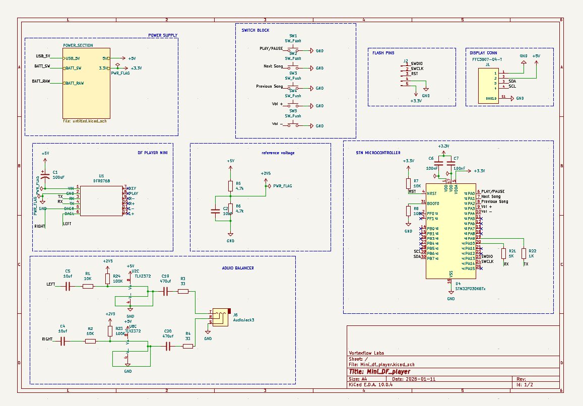
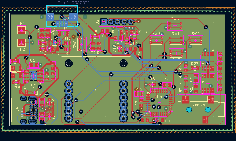
The PCB layout shows the component placement, routing, power-plane arrangement, mounting holes, connectors, and interface sections.
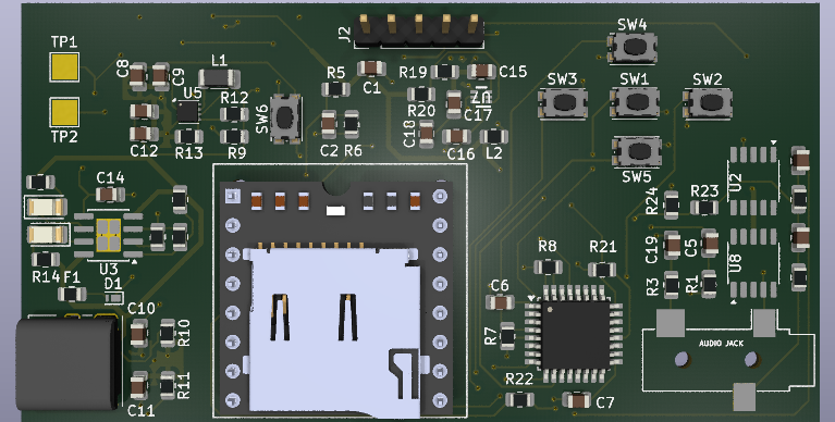
The 3D view is used to verify component placement, board dimensions, connector orientation, and the overall mechanical arrangement before fabrication.
Mini_df_player/
│
├── README.md
├── .gitignore
│
├── schematic/
│   └── ...
│
├── pcb/
│   └── ...
│
├── images/
│   ├── PCB_Schematic.png
│   ├── PCB_Layout.png
│   ├── 3D.png
│   └── Layer_Stack.png
│
├── firmware/
│   └── ...
│
└── datasheets/
    └── ...
The exact folder structure can be expanded as firmware, documentation, and manufacturing files are added.
The main goal of this project is to build a compact, custom MP3 player rather than relying on a ready-made development board.
The design focuses on:
Planned documentation and development can include:
Rohan Rathod
Electronics & Communication Engineering
Embedded Systems / PCB Design / Hardware Design Engineer
| Qty | Value | Footprint | References |
|---|---|---|---|
| 5 | 100nF | Capacitor_SMD:C_0805_2012Metric | C6, C7, C9, C11, C16 |
| 5 | 22uF | Capacitor_SMD:C_0805_2012Metric | C8, C12, C13, C15, C18 |
| 5 | SW_Push | Button_Switch_SMD:SW_Push_1P1T_NO_CK_KMR2 | SW1, SW2, SW3, SW4, SW5 |
| 4 | 10K | Resistor_SMD:R_0805_2012Metric | R1, R2, R7, R8 |
| 3 | 100k | Resistor_SMD:R_0805_2012Metric | R9, R13, R19 |
| 3 | 10uf | Capacitor_SMD:C_0805_2012Metric | C2, C4, C5 |
| 2 | 100K | Resistor_SMD:R_0805_2012Metric | R23, R24 |
| 2 | 10k | Resistor_SMD:R_0805_2012Metric | R17, R18 |
| 2 | 10uF | Capacitor_SMD:C_0805_2012Metric | C10, C14 |
| 2 | 1K | Resistor_SMD:R_0805_2012Metric | R21, R22 |
| 2 | 1k | Resistor_SMD:R_0805_2012Metric | R14, R15 |
| 2 | 33 | Resistor_SMD:R_0805_2012Metric | R3, R4 |
| 2 | 4.7k | Resistor_SMD:R_0805_2012Metric | R5, R6 |
| 2 | 470uf | Capacitor_SMD:C_0805_2012Metric | C19, C20 |
| 2 | 5.1K | Resistor_SMD:R_0805_2012Metric | R10, R11 |
| 2 | LED | LED_SMD:LED_1206_3216Metric | D2, D3 |
| 2 | TLV2372 | Package_SO:SOIC-10_3.9x4.9mm_P1mm | U2, U8 |
| 2 | TestPoint | TestPoint:TestPoint_Pad_2.5x2.5mm | TP1, TP2 |
| 1 | 100uF | Capacitor_SMD:C_0805_2012Metric | C1 |
| 1 | 10uH | Inductor_SMD:L_1206_3216Metric | L1 |
| 1 | 1uH | Resistor_SMD:R_0805_2012Metric | L2 |
| 1 | 2K | Resistor_SMD:R_0805_2012Metric | R16 |
| 1 | 316K | Resistor_SMD:R_0805_2012Metric | R12 |
| 1 | 47uF | Capacitor_SMD:C_0805_2012Metric | C17 |
| 1 | 510k | Resistor_SMD:R_0805_2012Metric | R20 |
| 1 | AudioJack3 | Connector_Audio:Jack_3.5mm_CUI_SJ-3523-SMT_Horizontal | J6 |
| 1 | Conn_01x05_Pin | Connector_PinHeader_2.54mm:PinHeader_1x05_P2.54mm_Vertical | J2 |
| 1 | DFR0768 | DFR0768-DFROBOT-Symbol-Kicad-563352:DFR0768 | U1 |
| 1 | FFC3B07-04-T | FFC3B07-04-T:GCT_FFC3B07-04-T | J1 |
| 1 | Fuse_Small | Fuse:Fuse_0805_2012Metric | F1 |
| 1 | PTVS5V0Z1USK | Diode_SMD:Nexperia_DSN1608-2_1.6x0.8mm | D1 |
| 1 | STM32F030K6Tx | Package_QFP:LQFP-32_7x7mm_P0.8mm | U4 |
| 1 | SW_SPST | Button_Switch_SMD:SW_Push_1P1T_NO_CK_KMR2 | SW6 |
| 1 | TP4056-42-ESOP8 | Package_SO:SOIC-8-1EP_3.9x4.9mm_P1.27mm_EP2.41x3.3mm_ThermalVias | U3 |
| 1 | TPS61023DRLR | footprints:DRL0006A | U7 |
| 1 | TPS62162DSG | Package_SON:WSON-8-1EP_2x2mm_P0.5mm_EP0.9x1.6mm_ThermalVias | U5 |
| 1 | USB_C_Receptacle_USB2.0_14P | Connector_USB:USB_C_Receptacle_GCT_USB4085 | J4 |
RohanRathod2605/PCB_HOBBY_PROJECTS
A custom MP3 audio player PCB designed around an STM32 microcontroller and the DFPlayer Mini audio module.


emertcakir/OpenAirScope
Open-source air quality and environmental monitoring node with STM32H743 + ESP32-C3, LoRaWAN, RS485, USB-C, Li-ion charging, and multi-sensor support.

emertcakir/OmniProbe
Open-source SWD, JTAG, UART, SPI, I2C and Logic Analyzer platform powered by RP2040

kwiecinski/BMS-and-offgrid-photovoltaic-management-system
Project contains BMS for lead-acid batteries and ESP-based board used to pull information from EASUN offgrid inverter, energy meters and sensors.

emertcakir/uPIC46
PIC18F46K22-based versatile development board with CAN, RS-485, EEPROM, RTC, and user LEDs

Durgpratap07/NovaCore-V1
Professional open-source STM32G431 development platform featuring a 4-layer PCB, USB Type-C, modular interfaces, and production-inspired hardware design for embedded systems development.


Conor-Dunlop/FYP_datalogger
render of the datalogger with power board (yes i know it need routed)
It measures 80 × 42 mm and has 4 copper layers, 1.6 mm thick.
68 parts, built around the TLV2372IP, TPS62162DSG, DFR0768 and TP4056-42-ESOP8. The full list of its parts is on this page, with links to each part's symbol and footprint where PCBKit's library has them.
From the RohanRathod2605/PCB_HOBBY_PROJECTS repository on GitHub, at the commit this page was made from: the board is Mini_df_player/Mini_df_player.kicad_pcb and its schematic Mini-Arduino/Arduino_Uno.kicad_sch. PCBKit opens the board in the browser, with nothing to install.
Its repository states no licence, so its author keeps all rights: ask RohanRathod2605 before reusing the design.