2 layers189.6 × 14.6 mm
Arm interface board mirrored
Roboy/Arm_interface_board
Board containing all the control units and power distribution for the servos in the arms.
65 parts1
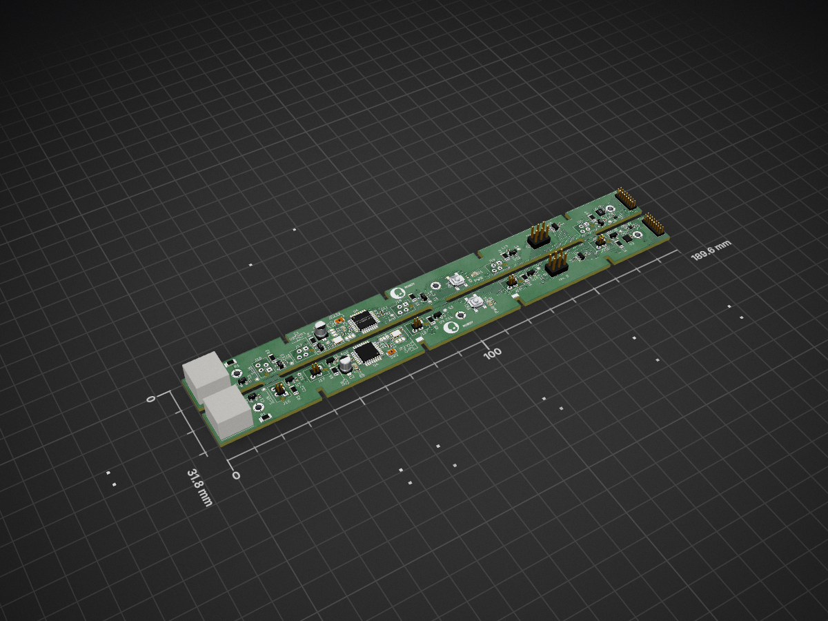
 Roboy/Arm_interface_board1
Board containing all the control units and power distribution for the servos in the arms.
Arm interface board panel is an open-source printed circuit board by Roboy, from the Roboy/Arm_interface_board repository on GitHub. It is a 2-layer board of 189.6 × 31.8 mm with 129 parts on 45 nets, routed with 2,287 tracks and 349 vias.
It is built around the ATMEGA328PB-AU, BMI160 and MIC5504-3.3YM5, with the NTS0102GT among its other parts. Its parts include 33 capacitors, 20 ICs, 18 resistors, 16 connectors and 4 diodes. It belongs with the interfaces and adapters boards and the AVR (ATmega, ATtiny) boards of this library.


Board containing all the control units and power distribution for the servos in the arms.
Check and/or solder the clock crystal on the board. Bridge the appropiate pads in order to enable it or make use of the extra two pins.
Crimp the connectors for power/i2c and the servos according to the following diagram:
Be careful and rearrange the connections before crimping if needed. Also make sure the cables exit the connector in an appropiate direction, to avoid loops.
The board can be programmed with the Arduino IDE but some setup is required.
This is partially the result of a mistake in ordering the uControllers, so the board is not actually designed to fit the chip. Even so it works without much modifications, although one should exercise special care to tristate the pins that are connected directly to power (A & B).
You need to install extra packages to enable compatibility with this chip in
the Arduino IDE.
Add the following URLs to the Additional Boards Manager URLs:
https://mcudude.github.io/MiniCore/package_MCUdude_MiniCore_index.jsonThis one enables and advanced bootloader and the extra functions in the PB series. For this you also need the latest AVR toolchain (version 1.6.206). Add:
https://downloads.arduino.cc/packages/package_avr_3.6.0_index.jsonto your Boards Manager.\
After you do this you can install the Minicore and update the Arduino AVR boards to 1.6.207 (AVR toolchain).
To flash the board you need to use an ISP programmer. The easiest way is to use an arduino as the programmer. You can do this by flashing any Arduino board with the code from Examples>11. ArduinoISP>ArduinoISP. Afterwards you can select the AVR chip from the Minicore boards and configure it for the specified clock, etc. With all options set you can burn the bootloader by selecting "Arduino as ISP" in the Programmer window.\
Sadly with this version of the AVR toolchain, for some reason the flashing does not work out of the box.
You require the latest version of avrdude, and the only way is by compiling
it from the source.
After you install it the flashing procedure is a bit different. You have to first
compile your code, and then using your freshly built avrdude version upload it
to your board.
UPDATE: downgrade to avr boards 1.6.23 and install arduino isp on atmega 2560. switch to 1.6.207 and install bootloader.
sudo ./avrdude -Cavrdude.conf -v -pm328p -cstk500v1 -P/dev/ttyACM0 -b19200 -D -Uflash:w:/tmp/arduino_build_XXXXXX/roboy_arm_board.ino.hex:i -F
in above command replace XXXXXX with your build number
| Qty | Value | Footprint | References |
|---|---|---|---|
| 23 | 100n | Capacitor_SMD:C_0402_1005Metric | C1, C1, C10, C10, C11, C11, C12, C12, C13, C13, C14, C14, C15, C15, C16, C16 +7 |
| 14 | TEST_1P | TestPoint:TestPoint_Pad_D1.0mm | Aref1, Aref1, S-IN1, S-IN1, S1, S1, S2, S2, S3, S3, S4, S4, S5, S5 |
| 12 | INA180 | Package_TO_SOT_SMD:SOT-23-5 | U1, U1, U7, U7, U8, U8, U9, U9, U10, U10, U11, U11 |
| 10 | 10mOhm | Resistor_SMD:R_1206_3216Metric | R3, R3, R4, R4, R5, R5, R6, R6, R7, R7 |
| 10 | CONN_01X04 | custom_lib:TE-Connectivity_Micro-Match_connector_02x02_Pitch_1.27mm | J16, J16, J17, J17, J18, J18, J19, J19, J20, J20 |
| 6 | Mounting_Hole_PAD | MountingHole:MountingHole_2.2mm_M2_DIN965_Pad | MK1, MK1, MK2, MK2, MK3, MK3 |
| 4 | 10k | Resistor_SMD:R_0402_1005Metric | R2, R2, R9, R9 |
| 4 | 1u | Capacitor_SMD:C_0402_1005Metric | C6, C6, C7, C7 |
| 4 | 22p | Capacitor_SMD:C_0402_1005Metric | C4, C4, C5, C5 |
| 2 | 1k | Resistor_SMD:R_0402_1005Metric | R8, R8 |
| 2 | 1mOhm | Resistor_SMD:R_1206_3216Metric | R1, R1 |
| 2 | 22u | Capacitor_SMD:CP_Elec_4x5.3 | C2, C2 |
| 2 | ATMEGA328PB-AU | Package_QFP:TQFP-32_7x7mm_P0.8mm | U4, U4 |
| 2 | BMI160 | Package_LGA:Bosch_LGA-14_3x2.5mm_P0.5mm | U2, U2 |
| 2 | CONN_02X08 | Connector_PinHeader_1.27mm:PinHeader_2x08_P1.27mm_Vertical | J1, J1 |
| 2 | ICSP | Connector_PinHeader_2.54mm:PinHeader_2x03_P2.54mm_Vertical | J3, J3 |
| 2 | JST_PHD_connector_02x05_angled_male | custom_lib:JST_S10B-PHDSS_2x05x2.00mm_Angled | J6, J6 |
| 2 | LED | LED_SMD:LED_0603_1608Metric | D1, D1 |
| 2 | LOGO | custom_lib:R1_eyes_mask_5.5mm | G***, G*** |
| 2 | LOGO | custom_lib:R1_ear_silk_5.5mm | G***, G*** |
| 2 | LOGO | custom_lib:Roboy_text_5.5mm | G***, G*** |
| 2 | LOGO | custom_lib:R1_face_mask_5.5mm | G***, G*** |
| 2 | MIC5504-3.3YM5 | Package_TO_SOT_SMD:SOT-23-5 | U5, U5 |
| 2 | NTS0102 | Package_SON:X2SON-8_1.4x1mm_P0.35mm | U3, U3 |
| 2 | SW_Push | Button_Switch_SMD:SW_SPST_SKQG | SW1, SW1 |
| 2 | TSX-3225 20MHz | Crystal:Crystal_SMD_TXC_7M-4Pin_3.2x2.5mm | Y1, Y1 |
| 2 | USER_LED(PB0) | LED_SMD:LED_0603_1608Metric | D2, D2 |
| 2 | USER_SW | custom_lib:SW_SPST_KXT3 | SW2, SW2 |
| 2 | XTAL_EN1 | Jumper:SolderJumper-3_P1.3mm_Open_RoundedPad1.0x1.5mm | JP1, JP1 |
| 2 | XTAL_EN2 | Jumper:SolderJumper-3_P1.3mm_Open_RoundedPad1.0x1.5mm | JP2, JP2 |
Roboy/Arm_interface_board
Board containing all the control units and power distribution for the servos in the arms.


NarekKalikian/Microcontroller-Projects
A variety of microcontroller projects combining principles of computer engineering, electrical engineering, circuit design, and programming.


antmicro/jetson-orin-baseboard
Baseboard targetting the NVIDIA Jetson Orin Nano and Jetson Orin NX

antmicro/snapdragon-845-baseboard
https://antmicro.com/blog/2022/04/open-source-snapdragon-845-baseboard/

antmicro/jetson-agx-thor-baseboard
Open hardware baseboard for Nvidia Jetson Thor AGX T5000 System on Module

antmicro/polarfire-som
System on Module based on Microchip PolarFire MPFS250T SoC
It measures 189.6 × 31.8 mm and has 2 copper layers, 1.6 mm thick.
129 parts, built around the ATMEGA328PB-AU, BMI160, MIC5504-3.3YM5 and NTS0102GT. The full list of its parts is on this page, with links to each part's symbol and footprint where PCBKit's library has them.
From the Roboy/Arm_interface_board repository on GitHub, at the commit this page was made from: the board is Arm_interface_board_panel/Arm_interface_board_panel.kicad_pcb. PCBKit opens the board in the browser, with nothing to install.
Its repository states no licence, so its author keeps all rights: ask Roboy before reusing the design.