2 layers90 × 38 mm
LCD OLinuXino-5TS Rev.B
OLIMEX/OLINUXINO
OLINUXINO is Open Source / Open Hardware, low cost from EUR 24 Linux Industrial grade Single Board Computer capable to operate -25+85C
56 parts1.5k
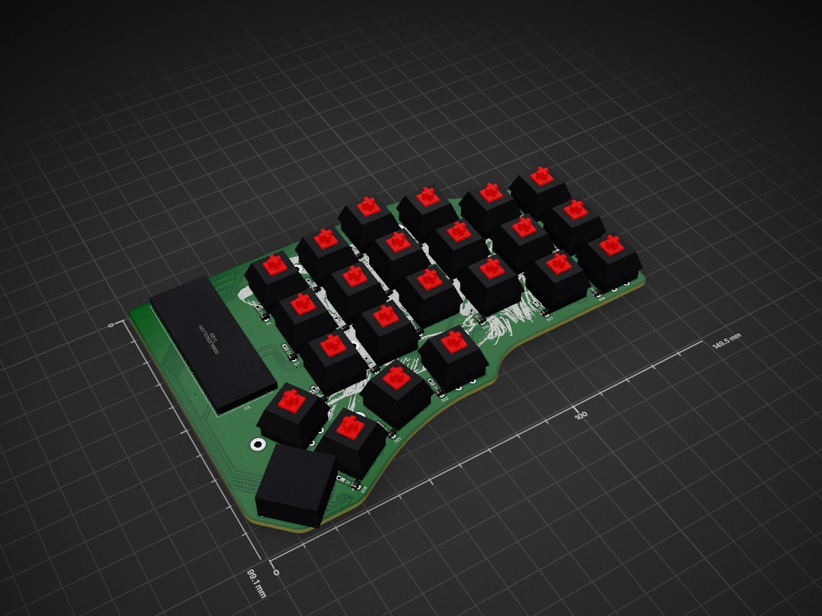
 RobK-0/PacificSound_SplitKeyboard4
Custom Column Stagger Split Keyboard
PacificSound is an open-source printed circuit board by RobK-0, from the RobK-0/PacificSound_SplitKeyboard repository on GitHub. It is a 2-layer board of 149.5 × 99.1 mm with 56 parts on 59 nets, routed with 868 tracks and 18 vias.
Its parts include 22 diodes, 22 switches, 1 IC and 1 connector. It belongs with the keyboards and input boards of this library.
This keyboard is an initial attempt at making a custom ergonomic column stagger split keyboard. It was the result of wanting to design a column stagger keyboard that operated using the STM32F4XX development boards (BlackPill). The generation of the PCB contained here was a result of a PCB promotion that offered free prototypes so long as they fit within 150mm X 100mm so I rearranged things to fit in. Rotary encoder positions were included (because why not...) and are hooked up to the timer channels so that they can be put in encoder mode and rely on the STM hardware and software to keep track of the encoders. All three encoders have separate lines. The PCBs are reversable and the plan was to make the switch footprints as compatible with switch variants as possible (for soldering, not hot swap). Although I only have MX type switches so that's all I've tested with so far. I also wanted to be sure I could make use of the SPI capability on these boards to (theoretically) be able to maximize data transfer between the halves and limit inefficiency and latency. The plan is also to explore the use of DMA for fast transfers and FreeRTOS for scheduling. In prototypint I explored QMK compatible setups but I did not like the idea of using these boards with a less efficient serial communication when they are capable of more. So then I explored creating code using the STM software and compilation and I figured I could play around with the creation of some basic firmware. So there is no proper firmware for this keyboard. Due to the use of SPI the boards are not compatible with QMK (to the best of my knowledge).


The first mistake made was the use of pin B2. Although I was not planning on having compatibility with QMK, I initially used QMK on one half to test it for any issues. I discovered that the use of pin B2 as a row pin caused QMK to trigger all keys in a column whenever a key connected to that row was pressed. I checked a breadboard setup with a single key attached and it gave the same issue. The issue was consistent accross several MCUs so I concluded it was an issue with using pin B2 as a row pin with column to row diodes. B2 is a board hardware pin for booting and, as such, it has an pulldown resistor on the BlackPill. My guess is that this pulldown resistor causes problems. The issue is easily fixed in the firmware I have written. The rows are used as output lines and the columns are used as input lines. The columns are set in the code to have the internal pull-up resistors enabled so that they all normally sense high. The rows are all normally set to high. Then during the matrix sweep the rows are sequentially pulled low and the columns are read to detect any low signals (a pressed switch will pull the column line low). But if I were updating the design I would not use pin B2 as a row line since it is not necessary as there are other pins available.
The next issue I discovered was with the ethernet jack (RJ45). In my efforts to squeeze into the free prototype space I moved the jack inboard and rotated it. The orientation of the jack means that the locking tab on the cable is up against the PCB and is not accessible to depress for removal of the cable. In order to remove a cable something must be slid between the locking tab and the PCB and then lifted up (eg a guitar pick). If I were updating this design I would either move the jack over to the edge (likely requires widening the PCB) or do an edge cut up to the face of the jack. Presently the traces from the ethernet jack run directly along where the cable comes in so they would need to be rerouted even if just the additional cutaway was added.
The last update I would do (that I know of at the moment) is I would connect the USART TX and RX as I've heard that people have gotten that working in QMK (although I didn't have much luck with it when I tried). This, along with fixing the B2 pin issue, should open it up for use with QMK instead of requiring custom firmware. There are 8 conductors in the RJ45 jack. I wanted SPI communication (needs 3 lines although I hooked up the NSS line even though it's not needed) and power and ground are, of course, required. I doubled up on power and ground lines but, if I hadn't done that, there would have been spare lines in the ethernet cable for USART.
A simple set of example firmware code files are contained in the Firmware folder. I have the keyboard now functioning in a basic capacity with some layers. This code was created using the STM Cube IDE software. The USB HID files that are included (HID Class in Middlewares) when the code is generated in the software (after configuring the MCU for use as a USB HID device) are set to a default of being a mouse. These need to be changed to make the device a keyboard. The "usbd_hid.h" and "usbd_hid.c" must be updated for the compiled code to be a keyboard. A quick internet search should show what the necessary changes are. I have only included the main code files where I have added in my code for my basic split keyboard setup that is presently working.
A python script is also included for generating keycode vectors from more standard form text keycode arrays. The keycode vectors can then be copied into the firmware main files. These vectors are used for interpreting the keyboard matrix and sending codes to the computer. Modifiers are stored in a separate vector. So some keys can be represented by a key in the keycode vector and a modifier in the modifier vector. Eg. an exclamation can be sent by a single key that has the keycode 1 in the keycode vector and right or left shift at the same position the modifier vector.
One last thing, for development on these boards I have found using the ST Link to be very valuable. I have not had much luck with the DFU bootloader on these BlackPill boards so any uploading of code without the ST Link would have been very frustrating. Also, the ST Link allows for debugging of the code while it's running on the BlackPill boards so that is very useful. I used the official ST Link V3 Mini for development and uploading code.
| Qty | Value | Footprint | References |
|---|---|---|---|
| 22 | D | PacificSound:D_TH_SMD | D1, D2, D3, D10, D11, D12, D13, D14, D15, D16, D17, D18, D19, D20, D21, D22 +6 |
| 19 | SW_Push | PacificSound:MX_ALPS_PG1350_noLed | SW1, SW2, SW3, SW4, SW5, SW6, SW10, SW11, SW12, SW13, SW14, SW15, SW16, SW17, SW20, SW21 +3 |
| 8 | M2 | PacificSound:MountingHole_2.2mm_M2_Pad | H1, H2, H3, H4, H5, H6, H7, H8 |
| 3 | Rotary_Encoder_Switch | PacificSound:MX_ALPS_PG1350_Rotary | SW18, SW19, SW22 |
| 1 | 8P8C | PacificSound:GMX-SMT2-S-88 | J1 |
| 1 | Conn_02x20_Counter_Clockwise | PacificSound:BlackPill | U1 |
| 1 | M2 | PacificSound:RightSideArt | H9 |
| 1 | M2 | PacificSound:LeftSideArt | H10 |
OLIMEX/OLINUXINO
OLINUXINO is Open Source / Open Hardware, low cost from EUR 24 Linux Industrial grade Single Board Computer capable to operate -25+85C

hackclub/OnBoard
💡 Join 1,000 teenagers and make your first PCB with a $100 grant!


GEIGEIGEIST/KLOTZ
KLOTZ is 34 keys column-staggered split keyboard. It uses an encoder and three status LEDs on each side.

ergonautkb/one
Ergonaut One is an open-source ergonomic wireless split mechanical keyboard designed by Ergonaut Keyboards.

matthewcieplak/super-sixteen
Code and schematics for the Super Sixteen Eurorack sequencer

EnriqueNeyra/Aeroq
An Indoor Air Quality Monitor Powered by ESP32, SCD40, and SEN54
It measures 149.5 × 99.1 mm and has 2 copper layers, 1.6 mm thick.
56 parts. The full list of its parts is on this page, with links to each part's symbol and footprint where PCBKit's library has them.
From the RobK-0/PacificSound_SplitKeyboard repository on GitHub, at the commit this page was made from: the board is KiCad/PacificSound.kicad_pcb. PCBKit opens the board in the browser, with nothing to install.
Its repository states no licence, so its author keeps all rights: ask RobK-0 before reusing the design.