2 layers191.3 × 181.7 mm
IO Card G3
PerMalmberg/IO-Card-G3
This is my custom I/O card, third generation. Main purpose is to serve as an alarm system.
400 parts7MIT
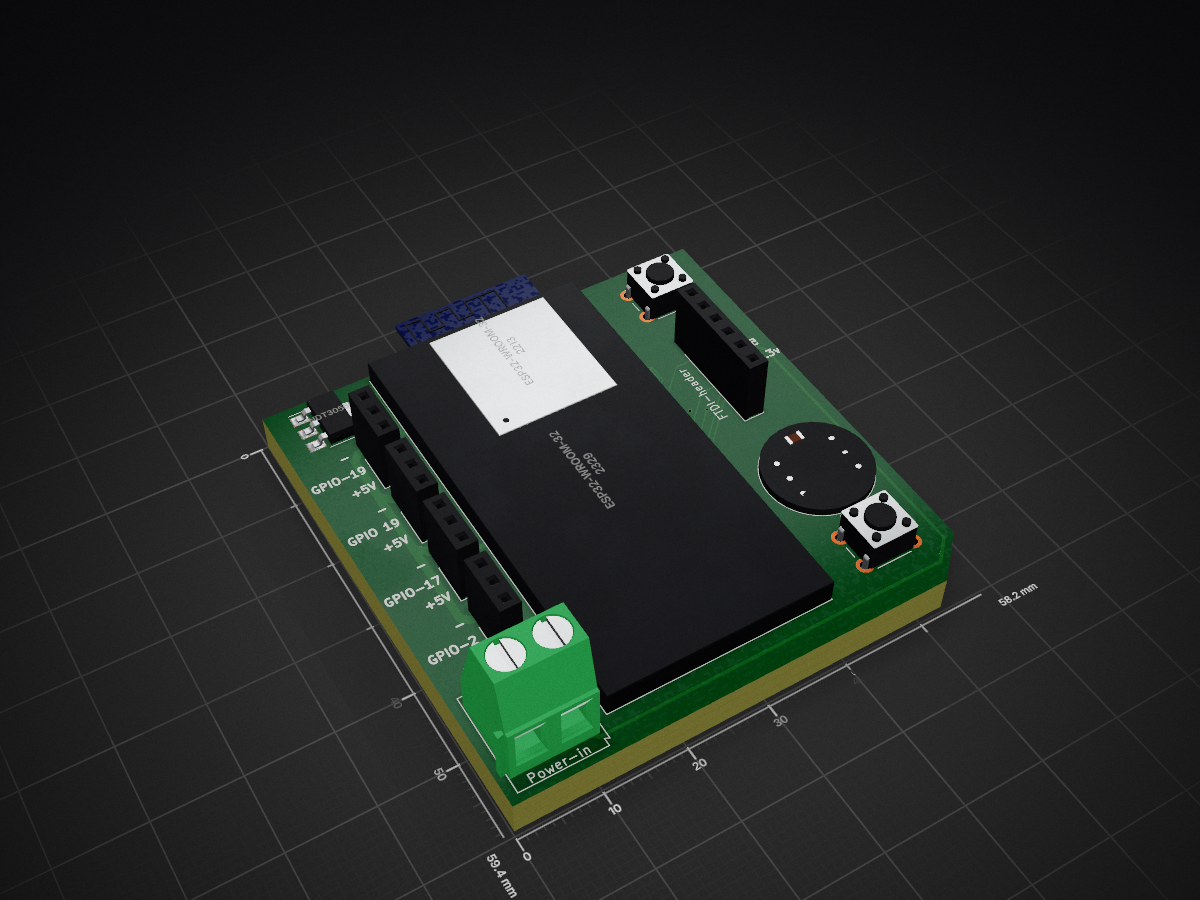
 Richard42Graham/WLED-MOUSE1
A WLED pcb for use with a microphone, and some othere bits, mainly for workshops and decoration.
WLED MOUSE is an open-source printed circuit board by Richard42Graham, from the Richard42Graham/WLED-MOUSE repository on GitHub, published under the MIT licence. It is a 4-layer board of 58.2 × 59.4 mm with 21 parts on 65 nets, routed with 381 tracks and 36 vias.
It is built around the ESP32-WROOM-32D, SN74LV4T125PW and INMP441, with the NDT3055L among its other parts. Its parts include 6 connectors, 4 capacitors, 3 ICs, 2 resistors and 2 switches. It belongs with the audio and music boards and the ESP32 boards of this library.


Note: PCB is still very much work in progress
PCB files for a for ESP32 board that can attach an INMP441 or ICS-43434 I²S microphone. It is intended to use together with SR-WLED for mixing sound reactive and addressable LEDs together.
The INMP441 is an omnidirectional digital microphone which communicates via I²S. It can be bought from a number of places, for example Aliexpress.
Hookup instructions is taken from the SR-WLED wiki.
| from INMP441, ICS-43434 | to ESP32 GPIO | |
|---|---|---|
| L/R | Gnd | ground => left channel. Don't leave this pin unconnected! |
| SD | 32 | serial data |
| WS | 15 | left right clock |
| SCK | 14 | serial clock |
| VDD | 3.3V | power don't use 5V! |
| GND | Gnd | ground, 0V |
Generic I2S| Qty | Value | Footprint | References |
|---|---|---|---|
| 4 | Pixel-strip | Connector_PinSocket_2.54mm:PinSocket_1x03_P2.54mm_Vertical | J4, J6, J7, J8 |
| 3 | C | Capacitor_SMD:C_0805_2012Metric | C1, C3, C4 |
| 2 | R | Resistor_SMD:R_0603_1608Metric | R1, R2 |
| 2 | SW_MEC_5E | Button_Switch_THT:SW_PUSH_6mm | SW1, SW2 |
| 1 | 25uF | Capacitor_SMD:C_0805_2012Metric | C2 |
| 1 | ESP32-WROOM-32D | RF_Module:ESP32-WROOM-32 | U2 |
| 1 | ESP32-WROOM-32D | esp32:ESP32-DEVKITC-32D | U1 |
| 1 | FTDI-header | Connector_PinSocket_2.54mm:PinSocket_1x06_P2.54mm_Vertical | J1 |
| 1 | INMP441 | mic:MIC_DMM-4026-B-I2S-R | M1 |
| 1 | INMP441-TH | mic:MIC_DMM-4026-B-I2S-R-TH | M2 |
| 1 | NDT3055L | Package_TO_SOT_SMD:SOT-223-3_TabPin2 | Q1 |
| 1 | Power-in | TerminalBlock:TerminalBlock_Altech_AK300-2_P5.00mm | J2 |
| 1 | SN74LV4T125 | Package_SO:TSSOP-14_4.4x5mm_P0.65mm | U3 |
| 1 | SolderJumper_3_Bridged12 | Jumper:SolderJumper-3_P1.3mm_Open_RoundedPad1.0x1.5mm | JP1 |
PerMalmberg/IO-Card-G3
This is my custom I/O card, third generation. Main purpose is to serve as an alarm system.


NEOgHacking/SCORPION-MAX-V1
4x Power Mosfets for controlling heated beds, heaters, ext.

captainchapster/Eigentime32
A self-contained pocket watch that keeps its own time for a decade. No GPS, one coin cell, one PCB.


engstad/AstroCam
My hobby project is to create a camera suitable for astronomy pictures. Here you can follow my work. It is slow going, since I don't have much time to allocate for this. So don't expect too many updates.

TheColonelYoung/Aether
Some parts are salvageable from original board: - Cables for LEDs - IR receiver with cable - Buttons - Input power jack - Case

It measures 58.2 × 59.4 mm and has 4 copper layers, 4.69 mm thick.
21 parts, built around the ESP32-WROOM-32D, SN74LV4T125PW, INMP441 and NDT3055L. The full list of its parts is on this page, with links to each part's symbol and footprint where PCBKit's library has them.
From the Richard42Graham/WLED-MOUSE repository on GitHub, at the commit this page was made from: the board is WLED-MOUSE.kicad_pcb and its schematic WLED-MOUSE.kicad_sch. PCBKit opens the board in the browser, with nothing to install.
Its repository publishes it under the MIT licence: you may reuse it on that licence's terms (keep the author's notice, and for a copyleft licence share your changes alike).