2 layers156.2 × 187.5 mm
 PerMalmberg/IO-Card-G37
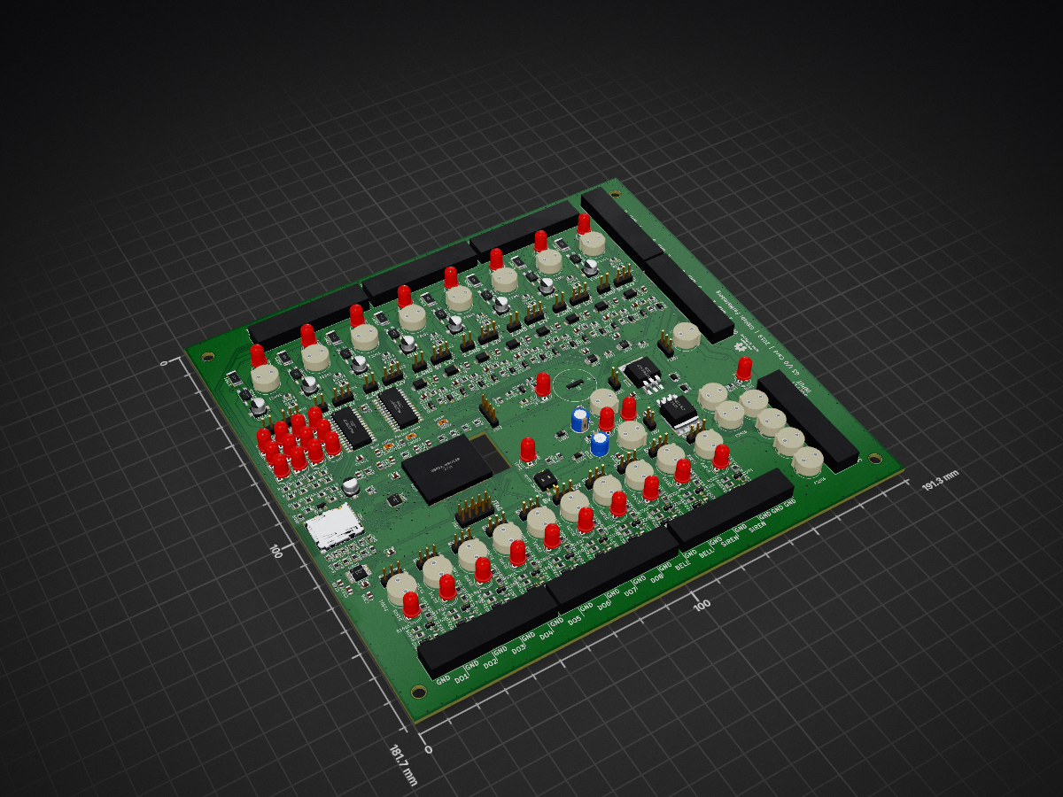
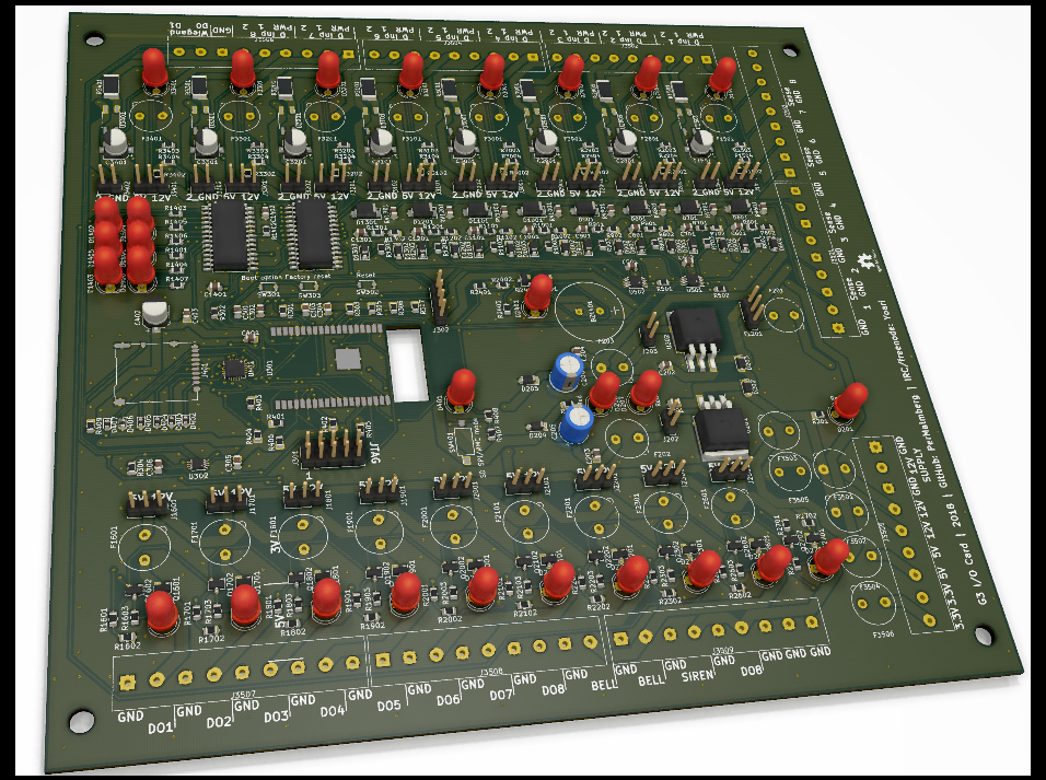
This is my custom I/O card, third generation. Main purpose is to serve as an alarm system.
IO Card G3 is an open-source printed circuit board by PerMalmberg, from the PerMalmberg/IO-Card-G3 repository on GitHub, published under the MIT licence. It is a 2-layer board of 191.3 × 181.7 mm with 400 parts on 276 nets, routed with 4,483 tracks and 893 vias.
It is built around the ESP32-WROVER-B, SN74LV4T125PW and ADS1115IDGST, with the BME280, LTV-354T and MCP23017-E/SS among its other parts. Its parts include 146 resistors, 89 diodes, 40 connectors, 39 capacitors and 27 fuses. It belongs with the ESP32 boards of this library.


This is my custom I/O card, third generation. Main purpose is to serve as an alarm system.
ANALOG_RDY_1 or ANALOG_RDY_2, read analog values; publish internally.DIA_Interrupt, read digital input values; publish internally.SIREN_CTRL, even though it is not on the I2C bus.<ID>/io/status/digital/input/<number><ID>/io/status/digital/output/<number><ID>/io/status/analog/input/<number><ID>/io/status/buzzer<ID>/io/status/siren<ID>/io/status/wiegand<ID>/io/set/channel_no, where channel_no is a number between 0 and 7.unix_timestamp value which tells when the item was created.true shall be interpreted as 'active', regardless if the input/output is active high or low. i.e. if the buzzer is making sounds, the the status is true.@ID@ is used to signify the ID of the device. Any instance of it in the replacement topic will be replaced with the device ID.execute_button button, usually '#' (but as its numerical button value). Any press on the cancel_button (*) clears any already entered numbers from the buffer.entry_timeout milliseconds, the bufer is cleared and no number series is published.entry_delay larger than 0 changes state, for the duration of the delay.armed no longer matches its configured armed_state. For analog inputs this means a value outside the range of value +/- allowed_hysteresis.
entry_delay if the triggering input has one larger than 0. Immediately sound the siren if an input other than the first is triggered during the wait time.armed has returned to its armed_state or not.
active set to false are never considered for any operation.SD_ENABLE to determine the mode for the SD Card.
ID from configuration.
ID to IOG3_<number>.(sorry, no 3D models for some components)
alarm.jsn
{
	"sensors":	{
		"digital":	{
			"input":	{
				"0":	{
					"name":	"D0",
					"enabled":	true,
					"armed_state":	true,
					"entry_delay":	5,
					"exit_delay":	5
				},
				"1":	{
					"name":	"1",
					"enabled":	false,
					"armed_state":	true,
					"entry_delay":	0,
					"exit_delay":	0
				},
				"2":	{
					"name":	"2",
					"enabled":	false,
					"armed_state":	true,
					"entry_delay":	0,
"exit_delay": 0dev_id.jsn
{
	"device_id":	"g3"
}
mqtt.jsn
{
	"keep_alive_seconds":	15,
	"broker":	{
		"address":	"1.2.3.4",
		"port":	1883
	}
}
notes.jsn
{
	"entry_delay": {
		"signal": [500, 500],
		"repeat": true
	},
	"exit_delay": {
		"signal": [1500, 500],
		"repeat": true
	},
	"error": {
		"signal": [250, 250, 250, 250, 250],
		"repeat": false
	},
	"armed": {
		"signal": [800, 200, 800, 200, 800],
		"repeat": false
	},
	"disarmed": {
		"signal": [800, 200, 800, 200],
		"repeat": false
	},
	"key_entry_timeout": {
		"signal": [200, 200, 200, 200, 200, 200],
		"repeat": false
	}
}
sntp.jsn
{
	"sntp_servers":	["0.se.pool.ntp.org", "1.se.pool.ntp.org", "2.se.pool.ntp.org"]
}
wifi.jsn
{
	"ssid":	"Your SSID",
	"password":	"Your password"
}| Qty | Value | Footprint | References |
|---|---|---|---|
| 33 | 1.65k | Resistor_SMD:R_0805_2012Metric | R1401, R1402, R1403, R1404, R1405, R1406, R1407, R1408, R1409, R1410, R1411, R1412, R1502, R1603, R1703, R1803 +17 |
| 31 | 10k | Resistor_SMD:R_0805_2012Metric | R301, R302, R303, R1504, R1605, R1705, R1805, R1905, R2005, R2105, R2205, R2305, R2401, R2804, R2904, R3004 +15 |
| 27 | 100n | Capacitor_SMD:C_0805_2012Metric | C201, C202, C203, C204, C301, C302, C304, C305, C306, C307, C1001, C1101, C1201, C1301, C1401, C1402 +11 |
| 21 | 470 | Resistor_SMD:R_0805_2012Metric | R1601, R1604, R1701, R1704, R1801, R1804, R1901, R1904, R2001, R2004, R2101, R2104, R2201, R2204, R2301, R2304 +5 |
| 20 | CZRQR52C6V8-HF | Diode_SMD:D_0402_1005Metric | D1602, D1603, D1702, D1703, D1802, D1803, D1902, D1903, D2002, D2003, D2102, D2103, D2202, D2203, D2302, D2303 +4 |
| 20 | Red | LED_THT:LED_D5.0mm | D201, D206, D207, D1402, D1403, D1405, D1406, D1408, D1409, D1411, D1412, D1501, D2801, D2901, D3001, D3101 +4 |
| 17 | xA | Fuse:Fuseholder_TR5_Littlefuse_No560_No460 | F201, F202, F203, F1501, F2801, F2901, F3001, F3101, F3201, F3301, F3401, F3501, F3502, F3503, F3504, F3505 +1 |
| 16 | 100 | Resistor_SMD:R_0805_2012Metric | R603, R703, R803, R903, R1003, R1103, R1203, R1303, R1503, R2803, R2903, R3003, R3103, R3203, R3303, R3403 |
| 16 | STPS0560Z | Diode_SMD:D_SOD-123 | D602, D603, D702, D703, D802, D803, D902, D903, D1002, D1003, D1102, D1103, D1202, D1203, D1302, D1303 |
| 11 | Green | LED_THT:LED_D5.0mm | D1601, D1701, D1801, D1901, D2001, D2101, D2201, D2301, D2401, D3202, D3302 |
| 11 | Si2312CD | Package_TO_SOT_SMD:SOT-23 | Q1601, Q1701, Q1801, Q1901, Q2001, Q2101, Q2201, Q2301, Q2401, Q3201, Q3301 |
| 11 | Si2323CDS | Package_TO_SOT_SMD:SOT-23 | Q1602, Q1702, Q1802, Q1902, Q2002, Q2102, Q2202, Q2302, Q2402, Q3202, Q3302 |
| 10 | 2.2k | Resistor_SMD:R_0805_2012Metric | R1602, R1702, R1802, R1902, R2002, R2102, R2202, R2302, R3208, R3308 |
| 10 | Power_select | Connector_PinHeader_2.54mm:PinHeader_1x03_P2.54mm_Vertical | J1601, J1701, J1801, J1901, J2001, J2101, J2201, J2301, J3203, J3303 |
| 10 | xA | Fuse:Fuseholder_TR5_Littelfuse_No560_No460 | F1601, F1701, F1801, F1901, F2001, F2101, F2201, F2301, F3202, F3302 |
| 9 | 10u | Capacitor_SMD:CP_Elec_5x4.5 | C402, C1501, C2801, C2901, C3001, C3101, C3201, C3301, C3401 |
| 8 | 1k | Resistor_SMD:R_2512_6332Metric | R1501, R2801, R2901, R3001, R3101, R3201, R3301, R3401 |
| 8 | 1k | Resistor_SMD:R_0805_2012Metric | R601, R701, R801, R901, R1001, R1101, R1201, R1301 |
| 8 | 2k | Resistor_SMD:R_0805_2012Metric | R602, R702, R802, R902, R1002, R1102, R1202, R1302 |
| 8 | B72510E250K062 | Capacitor_SMD:C_0805_2012Metric | RV601, RV701, RV801, RV901, RV1001, RV1101, RV1201, RV1301 |
| 8 | CDBA3100-HF | Diode_SMD:D_SMA | D601, D701, D801, D901, D1001, D1101, D1201, D1301 |
| 8 | Digital input GND | Connector_PinHeader_2.54mm:PinHeader_1x02_P2.54mm_Vertical | J1502, J2802, J2902, J3002, J3102, J3202, J3302, J3402 |
| 8 | Digital input supply | Connector_PinHeader_2.54mm:PinHeader_1x03_P2.54mm_Vertical | J1501, J2801, J2901, J3001, J3101, J3201, J3301, J3401 |
| 8 | LTV-354T | Package_SO:SO-4_4.4x3.6mm_P2.54mm | U1501, U2801, U2901, U3001, U3101, U3201, U3301, U3401 |
| 6 | 50k | Resistor_SMD:R_0805_2012Metric | R401, R402, R403, R404, R405, R406 |
| 6 | D_TVS | Diode_SMD:D_0603_1608Metric | D402, D403, D404, D405, D406, D407 |
| 4 | MountingHole | MountingHole:MountingHole_4.3mm_M4 | MH101, MH102, MH103, MH104 |
| 2 | 100u | Capacitor_THT:CP_Radial_D6.3mm_P2.50mm | C205, C206 |
| 2 | 120 | Resistor_SMD:R_0805_2012Metric | R2403, R2405 |
| 2 | ADS1115IDGST | Package_SO:TSSOP-10_3x3mm_P0.5mm | U501, U502 |
| 2 | Digital input | PerMalmberg:MOLEX_1x9_39544-3009 | J3504, J3506 |
| 2 | Digital output | PerMalmberg:MOLEX_1x9_39544-3009 | J3508, J3509 |
| 2 | GS2 | Connector_PinHeader_2.54mm:PinHeader_1x02_P2.54mm_Vertical | J202, J203 |
| 2 | MCP23017 | Package_SO:SOIC-28W_7.5x17.9mm_P1.27mm | U1401, U1402 |
| 2 | RBR3MM30ATR | Diode_SMD:D_SOD-123F | D202, D203 |
| 2 | Sense | PerMalmberg:MOLEX_1x9_39544-3009 | J3501, J3503 |
| 1 | 2.55k | Resistor_SMD:R_0805_2012Metric | R203 |
| 1 | 22u | Capacitor_SMD:C_0805_2012Metric | C303 |
| 1 | 3.3V | Diode_SMD:D_SOD-123 | D204 |
| 1 | 4.7k | Resistor_SMD:R_0805_2012Metric | R2404 |
| 1 | 5.1V | Diode_SMD:D_SOD-123 | D205 |
| 1 | 6.04k | Resistor_SMD:R_0805_2012Metric | R201 |
| 1 | BME280 | Connector_PinHeader_2.54mm:PinHeader_1x04_P2.54mm_Vertical | J302 |
| 1 | Boot option | Button_Switch_SMD:SW_SPST_CK_KXT3 | SW301 |
| 1 | Debug | Connector_PinHeader_2.54mm:PinHeader_2x05_P2.54mm_Vertical | J301 |
| 1 | Digital Input | PerMalmberg:MOLEX_1x9_39544-3009 | J3502 |
| 1 | Digital Output | PerMalmberg:MOLEX_1x9_39544-3009 | J3507 |
| 1 | EMI_Filter_LCL | Connector_PinHeader_2.54mm:PinHeader_1x03_P2.54mm_Vertical | FL201 |
| 1 | ESP32_WROVER | PerMalmberg:ESP32_WROVER | U301 |
| 1 | Factory reset | Button_Switch_SMD:SW_SPST_CK_KXT3 | SW303 |
| 1 | LM1084-3.3 | Package_TO_SOT_SMD:TO-263-3_TabPin2 | U201 |
| 1 | LM1084-5.0 | Package_TO_SOT_SMD:TO-263-3_TabPin2 | U202 |
| 1 | Logo_Open_Hardware_Small | Symbol:OSHW-Logo2_7.3x6mm_SilkScreen | LOGO101 |
| 1 | MAX4948 | Package_DFN_QFN:QFN-24-1EP_4x4mm_P0.5mm_EP2.6x2.6mm_ThermalVias | U401 |
| 1 | MQTT Connected | LED_THT:LED_D5.0mm | D1410 |
| 1 | Micro_SD_Card_Det | Connector_Card:microSD_HC_Hirose_DM3AT-SF-PEJM5 | J401 |
| 1 | Power 12/5/3 | PerMalmberg:MOLEX_1x9_39544-3009 | J3505 |
| 1 | Reset | Button_Switch_SMD:SW_SPST_CK_KXT3 | SW302 |
| 1 | SD SPI/MMC mode | Button_Switch_SMD:SW_DIP_SPSTx02_Slide_Omron_A6S-210x_W8.9mm_P2.54mm | SW1 |
| 1 | SDC1610M5-01 | PerMalmberg:SDC1610M5-01_Buzzer_16diam_5pitch | BZ1401 |
| 1 | SDCard Init OK | LED_THT:LED_D5.0mm | D1401 |
| 1 | SN74LV4T125 | Package_SO:TSSOP-14_4.4x5mm_P0.65mm | U302 |
| 1 | SNTP Time set | LED_THT:LED_D5.0mm | D1407 |
| 1 | Wifi Connected | LED_THT:LED_D5.0mm | D1404 |
| 1 | ZXTN25050DFHTA | Package_TO_SOT_SMD:SOT-23 | Q401 |


rossuthoff/multichannel_led_driver
LED driver for up to nine LED strings

ductomn/Swarm-robot
Bachelor Thesis - Design and implementation of a cooperative robotic platform with simple communication


Andreasdahlberg/CANDrive
CANDrive is a brushed DC Motor Controller controlled via a CAN interface.

Andreasdahlberg/CANDriveHW
CANDrive is a brushed DC Motor Controller controlled via a CAN interface.

It measures 191.3 × 181.7 mm and has 2 copper layers, 1.6 mm thick.
400 parts, built around the ESP32-WROVER-B, SN74LV4T125PW, ADS1115IDGST and BME280. The full list of its parts is on this page, with links to each part's symbol and footprint where PCBKit's library has them.
From the PerMalmberg/IO-Card-G3 repository on GitHub, at the commit this page was made from: the board is hardware/G3.kicad_pcb. PCBKit opens the board in the browser, with nothing to install.
Its repository publishes it under the MIT licence: you may reuse it on that licence's terms (keep the author's notice, and for a copyleft licence share your changes alike).