nTerm2-S
[!NOTE]
This is the continuation of the design of the nTerm2-S (found here: https://github.com/RetepV/nTerm2-S). Now that I am reaching completion, I have decided to switch from using a CP2102 to using an FT231. The FT231 is just easier to solder with a soldering iron. Or better said: it CAN be soldered with a soldering iron, whereas with the CP2102 that's near impossible, it was a bad choice on my part.
The version with the CP2102 will be 'archived', i.e. frozen. It really does work, you can build it if you like, it will run any FabGL code and example (except the MS-Dos emulator for lack of memory). But I will abandon it and continue developing on the FT231 version.
This is my rendition of the uTerm2-S by Just4Fun (https://hackaday.io/project/181583-uterm2-s-a-multi-emulation-color-rs232-terminal). My one is in SMD, and I hopefully made it easily hand-solderable for everyone. Obviously the 'n' in nTerm stands for 'nano.' :P
The nTerm2-S has a slightly more usable form than the uTerm2-S, I think. Smaller and more of a format of a useful tool. A "throw it in a drawer and grab it when you need it"- type of device. Taking little desk space and layed out for quick plugging and unplugging serial devices. For that I have also made it so that it can switch between normal and cross-cable (null-modem) from software, so that all you need is one cable and don't need extender boxes or a special null-modem cable.
It can also switch between hardware-supported RTS/CTS and DTR/DSR handshaking. With the sidenote that DTR/DSR are connected to RTS/CTS of the ESP32: the ESP32 does not have dedicated DSR/DTR signals in it's UART. It should work fine that way with old hardware, as the ESP32 is so fast that it will probably never have to deassert DTR (in reality RTS) anyway. And if the data set deasserts DSR, it means that the ESP32 will actually see CTS deasserted, and wait until CTS asserts again before continuing.
The nTerm2-S is ultimately based on the FABGL library and board design from Fabrizio Di Vittori. http://www.fabglib.org. However, I skipped Fabrizio's implementation and based my design on Just4Fun's uTerm2-S. https://j4f.info/uterm2-s
This board will run all FabGL software and examples, except the PC emulator. The PC emulator needs PSRAM, but the nTerm2-S does not have enough I/O pins left to connect a PSRAM. Maybe I will do a V2 at some point, using an I/O expander to free up ESP32 pins for connecting a PSRAM and an SD card. Or maybe I will make a new design using a newer version CPU. But let's finish the nTerm2-S first... ;)
Software
For the software, please have a look here: https://github.com/RetepV/SporosTerm
All instructions for building the software from source are there. But I also provide releases with handy scripts/batch files to easily program the board.
Build instructions
I will provide build instructions here, when I actually have some. I'm going to build another one, and will make pictures.
Progress
27-2-2026
Oops... I made a boo boo...
I have completely forgotten about the 5K1 resistors on the CC1 and CC2 lines of the USB-C connector. And hence, no USB-C device will provide power to the board, except some cheap and probably dangerous USB-C chargers. I knew I should have added them, I remember even making a mental note, but yet I never added them. How could this happen? Well, apart from simply my inexperience with USB, I have been testing all these months with a nice and long Nintendo USB cable, which has a USB-A on one end and a USB-C on the other. And I had it plugged into a USB hub, because I'd rather risk burning out the hub than a USB port on my laptop. But USB-A will happily provide power to anything, so my board always powered up fine. It was not until I wanted to change some settings in the FT231, and used a USB-C cable to directly connect it to my laptop, that I found the board didn't want to power up. Major facepalm. 🤦
Worst part (or better part, I'm not sure yet) is that this is quite a common mistake that people make. I should have know better, but on the other hand: it does make me feel a bit better that I'm not the only one. 😆
I quickly confirmed that this was the problem by wiring up the two resistors. And yep, now USB-C is giving the board power.

Adding two resistors seems like a quick and easy thing to do. But not this time, as the area where the resistors had to go was too crowded. So I had to refactor that whole area to make place. But now it looks a bit nicer too.
I also took the opportunity to update the graphics on the board. I moved some to the back and made them bigger (turns out that JLCPCB doesn't charge extra for solder mask on the back), added the URLs to these repositories, and add the FabGL and j4f repositories as well.
So here's v0.12. Only two resistors changed. Let's play a game of Spot the Differences:

This also has a consequence for the videos that I made. The videos are for a v0.11 board. What should I do? Make new boards yet again, and reshoot the videos? Maybe it's a good idea, because I learned a few things in the mean time, and the quality of the videos would become better. But the v0.11 videos are quite informational and educational already. I have to ponder this over a little.
By the way, I tallied up the costs of all the components. It comes down to about €40 for one board. But this was without looking for lower prices, I just went with the prices from Reichelt (https://www.reichelt.com).
nTerm2-S FT231 BOM with prices.csv.zip
26-2-2026
I have been making videos while going from this:

To this:

I now have some video editing to do, which I have never done before in my life. Including adding a voiceover, because most of the time I was silent and concentrated during soldering. I did talk to myself in a few places, maybe I'll keep that. :)
A few mistakes were made, and I will show them uncensored. It resulted in a bunch of tips that are of general use when handsoldering SMD components. Let's see if I can make it educational. I hope that it will help some people take the plunge into SMD soldering. It's really not that hard. Just that you might need a 5x or 10x magnifying glass, like I do.
This is my fourth board (the other three were prototypes), and I was able to make it work in one go. When you watch the video, you'll see that I had a bit of jittery fingers, and that it caused me to make some mistakes. No shame in that!
16-2-2026
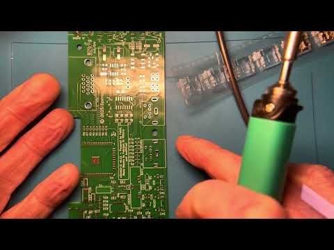
Just mentioning some progress here. I have started to build a new nTerm2-S, and am recording that. I have the handicap of not having great eyes anymore and have to solder using a magnifying glass these days. And this gets in the way of filming. So I had to rig something together. In the end I was able to ty my iPhone to the magnifying glass in such a way that I could look past it, while the iPhone looked straight down at my work area and my hands. That actually worked much better than I thought, except that if I accidentally touch the magnifying glass, the video wobbles a bit. :) Let's see if I can edit that out. No tricks, just honest handsoldering, including jittery hands, accidental baking of a resistor, and the occasional mistake that needed to be redone.
Anyway, here's a little unedited preview. Click it to play in Youtube.
3-12-2025
I found a little time to finally finish v0.11. This is it. I am not going to add anything more. Done deal. I will ask JLCPCB to fabricate a new set of v0.11 boards and will then build up one for the purpose of making pictures on how to solder one together. Maybe I'll make a video, which will be my first.
At the last possible moment, I added a 3-terminal pin header to optionally attach a 10K potmeter to, to use as volume control. I realised a bit late that if you build the amplifier and connect a speaker directly to the board, there is no way to control the volume. I can add volume control in software, but really: if you accidentally have the volume booming too loud, would you rather want to turn a volume pot or go into the setup menu, choose 'Audio', decrease the volume, and press Save? Anyway, it is optional and you can leave it out. Just don't forget to connect pins 1 and 2 on the 3-pin VOLUME header and solder R19. All info in the schematic.
I also improved some routing, and a few other little things.
2-11-2025
I have the Bluetooth working more or less great with Linux. I can pair, connect, disconnect, connect, disconnect, et
The problem of Macos, not properly being able to reconnect after a disconnect, seems to be a bug of Macos specifically. The Serial Port Profile (SPP) support on Macos is buggy. I have reported the bug with Apple, let's see wat happens.
1-11-2025
In between wrestling with trying to get the Bluetooth Serial Port Profile working and stable (which I am only moderately successful in, to be honest), I spent some time on a useless but fun thing: a signon screen. :)

About the Bluetooth SPP. It seems that I have it mostly under control now, it's quite usable and I'm not missing characters anymore. However, there is a problem that after pairing, it's only possible to connect one time. If we disconnect and try to connect again, the connection seems to be made, but no data is being transferred. If the nTerm2-S is 'forgotton' and paired again, it will work again for one connection only.
After browsing the internet, it seems that I am not the only one with this issue, and that it looks to be an issue with the ESP32's Bluetooth implementation loosing the pairing key for some reason.
There are some questions on the Espressif forums, and this one is quite detailed and seems to explain the issue quite well: https://esp32.com/viewtopic.php?p=151510&hilit=esp32+spp#p151510
26-10-2025
That newt had it coming, I swear!
@Fabrizio: it's really working well. Great job, thank you for all the work you did!

26-10-2025
I have been working on the software, and on testing. I don't have access to all types of hardware, but for now I have been testing with these:
- A Synertek SYM-1, which is the oldest computer that I currently own.
- An old(ish) Macbook (i7) running Ubuntu 24.04, with a serial dongle that is RS-232 V.24, i.e. uses -12V/+12V for communication.
- The latest version of the nTerm2-S, but without the audio and relay circuits (minimum configuration).
- A previous version of the nTerm2-S that I fully built for prototyping, and does have the audio and relay circuits.
I have been testing at different baud rates, and have been able to go all the way down to 110 baud successfully.
The SYM-1 doesn't go lower, so I thought to use my Linux machine to try agetty at 50 baud. But for some reason nothing under 110 baud would work. However, when I connect two nTerm2-S devices together, they can perfectly well communicate at 50 baud. So I suspect that the serial USB dongle has an issue with anything below 110 baud. I will have to check the signals with a scope to see what's really going on. The USB dongle uses a PL-2303 chip, and according to the datasheet it should be able to go down to at least 75 baud, and I suspect even lower. Maybe it's a driver issue.
On this latest prototype of the nTerm2-S, I did not populate the relay circuits. So to connect it to the Linux machine, I had to dig up a bunch of converters. And I had to quickly wire a null-modem converter too. So this reminded me again of why I added those relay circuits. They are worth it. :)

It IS actually a weird feeling to communicate with such a powerful Macbook over 110 baud. It really gave me the feeling that I was calling remotely into an old timesharing mainframe computer. :P
While testing with agetty, I found that I had forgotten to implement BRK functionality. So I quickly added that, and now I can ask agetty to cycle through a bunch of predetermined baud rates to match my nTerm2-S's baud rate.
Here's a picture of two nTerm2-S's connected to each other, where one has the relay circuits. No huge tree of converters, just one converter to go from DB25 to DB9, and then just set the Modem Type to 'Null modem' in the settings!

Another thing is the supported display resolution and display modes... Currently I offer 2 resolutions: 640x350 and 800x480. 800x480 is closest to the DEC VT340, which apparently was 800x500 pixels. At 800x480, there is just enough memory to have 8 colors (4 low and 4 high intensity). But it does give high resolution graphics, and it also gives a quite readable 132x25/50 characters (6 pixels wide characters).
At 640x350, I can have 16 colors. But what's more is, that if I use 640x350 monochrome, I can have the Bluetooth stack running! So it looks like I will support the following modes:
- 640x350, [80x24 + status bar, 80x25, 80x48 + status bar, 80x50], 2 colors, bluetooth
- 640x350, [80x24 + status bar, 80x25, 80x48 + status bar, 80x50], 16 colors, no bluetooth
- 800x480, [80x24 + status bar, 80x25, 80x48 + status bar, 80x50, 132x24 + status bar, 132x25, 132x48 + status bar, 132x50], 8 colors, no bluetooth
I do have a font that tries to show something readable when using 132x25 characters on a 640x350 resolution screen. It's not really something I take serious, but the font is there and is added quickly enough. Maybe it's worth it for some edge cases. Or just maybe, I could get a resolution of 800x350?
Higher resolutions than 800x480 are possible, but simply mean less colors because the ESP32 just does not have enough memory. There seems to be a solution for that, by adding PSRAM. But that would mean a hardware redesign, because there are no pins left to connect a PSRAM. I would have to add an I/O expander, either i2c or maybe 1-wire. That will only happen in a possible next version, which I will then probably also base on an ESP32-S3 (because it can do both UART and JTAG over USB, and is therefore tremendously much easier to debug).
I actually made a proof of concept already beginning of this year. But I will not build it (and it's not finished), as I really want to move on to the ESP32-S3 or maybe even something better.
https://github.com/RetepV/nTerm2-S-SD
25-10-2025
The last update was quite some time ago. I have been struggling with both time to work on this project, and struggling with the rendering issue of the terminal application. Somehow the glyph options of the Status Bar would sometimes 'bleed' over to the terminal text, causing letters to appear in reverse video. I had an inkling that this was being caused by the Status Bar rendering being interrupted by serial data being received and also rendered to the screen. Serial data is being received on an interrupt basis, so this was happening. However, I did not understand why.
It turns out that when we want to render a glyph on the Canvas, we use a function drawText(). But the glyph options (and foreground and background colors) are not passed together with the text. Instead, we use setGlyphOptions, setPenColor and setBrushColor to set up the parameters, and then call drawText, which will use the parameters that we set up. What the Canvas actually does with these calls is to post a message into a queue that will be read and processed by the DisplayController. This is necessary because the Canvas and the DisplayController code run on different cores and we need to take care of synchronising the messages: we cannot interrupt the DisplayController when we want, because that will lead to visible screen glitches. Using a queue is probably the easiest way to do this.
However, both the Canvas and the DisplayController keep their own version of those settings, i.e. there is more than one source of truth. The sources of truth are not updated at the same time, and that means that there is always a small amount of time where both will be out of sync. And this is the reason why sometimes the text received from the RS-232 was rendered with the glyphOptions of the Status Bar.
This is actually not so hard to fix. We just need to have only one source of truth, and pass the parameters together with the other relevant data (Glyph) through the queue. However, that would be a major fix, and actually a paradigm change. It could potentially have a lot of side effects, and I am not yet feeling up to handle that. Besides, it would be a backwards-compatibility breaking fix and so cannot be pushed back into Fabio's FabGL branch. And as I am only interested in the terminal emulation, I think I would better trip the FabGL library of all that is unnecessary and make a FabGLTerm or FabGLLite version or something. And I'm not sure if that is allowed by the license.
Anyway, another way to go is to leave everything as it is and simply add a drawGlyph command that takes glyphOptions, penColor and brushColor, and renders the glyph with the passed parameters instead of the (doubly) stored global glyphOptions, penColor and brushColor, call it drawGlyphWithOptions, and use that call to render the Status Bar. No sooner said than done, and the glitches disappeared. Success!
All the time that I was trying to work this out, I was wishing that I could connect a debugger to trace what was going on. But all the GPIO pins on the ESP32 are used for something, and there are no free pins to connect a JTAG debugger. This makes everything really hard to debug. If I make a next version of the nTerm2-S, I will choose for the ESP32 S3, which can do serial communications and JTAG over its USB port, making life so much easier.
Next steps are to clean up everything, reorganize the repository a bit, test with many more devices, and write some documentation. Possibly add a feature or two more.
What I have not mentioned before, is that I have also been busy implementing Bluetooth serial communications. The idea is that you can connect your PC to the Bluetooth UART and monitor what happens on the nTerm2-S. And more: you can send keystrokes to the nTerm2-S, which will forward it to the connected serial devices. The nTerm2-S is basically proxying between the serial device and the PC. The best part of this is that not only can you record the received serial data on the PC, but can also send data to the serial device, meaning that you can use the nTerm2-S to upload data. There are a few things to still iron out, but it's coming along quite nicely.
23-6-2025
Fixed a few small layout issues that I encountered while soldering, and then submitted as V0.10.
- Fixed orientation of C19.
- Changed orientations of R19 and C3. If you don't want the audio amplifier, you will still have to solder in the filter components R20, R21, C7 and C3. I placed C3 right under C7 now, and R19 (which does not need to be added) below that, making it more obvious what needs to be soldered and what not.
- Somehow the designation of C3 disappeared, I brought it back.
- Tweaked the positions of the connectors so that they are flush with the PCB edge. I should have done that earlier.
- Connected pins 2 and 3 of the CR2032 battery holder together. I didn't have the correct battery holder, so I soldered one in with a wire. I had to solder to pin 1 (-) and 3 (+) of the battery holder. But looking at the PCB, pin 2 is unconnected but also shows '+' in the solder mask. That's confusing, so I connected pin 2 to pin 3 so now both + pins can be used.
Here's the final result of v0.09. This is without the previously mentioned fixes, zoom in on the picture to find the issues. ;)

I thought it might be nice to show the equipment that I use to solder nTerm2-S. This is it. Nothing more (ok, I also wear reading glasses).
- A lamp with 2x magnifying glass
- A small 10x magnifying loupe
- A steel set of quality pincers
- Edsyn FL-22 flux
- A Pinecil DC5525 soldering iron with ST-BC2 tip (the short variant of the BC2)
- 0.5mm 60/40 rosin-core solder
- A Goobay silicone soldering mat
- Forgot to picture: a benchtop solder fume extractor, the most basic type
I also have a hot air station. But one of my goals is to make the nTerm2-S solderable without hot air, so I don't use it (I did need it for the CP2102, which is why I dropped that chip). I find that using hot air is not faster than hand soldering, possibly even slower. Hot air does have the benefit, though, that the components will align themselves automatically. The fastest way, however, will be to use solder paste with a stencil, and bake the PCB in an SMD oven. I don't have one, so hand soldering it is. ;)

And then software. Software is coming along quite well, but I have to iron out one quite major thing. The FabGL 'canvas' class works great if you only have one source of data. But I need to render the terminal text from serial input, but also the bottom status bar, so the canvas has 2 sources of data. Canvas, however, only has one set of text properties (bold, inverse, etc.). The serial input and status bar are sharing the text properties, and so I get some random inverse letters in the terminal text, when serial data is received while I'm in the middle of rendering the status bar. I really don't want to change FabGL much, but this is a fundamental problem of Canvas. It has only one render queue, and text properties are global to Canvas and are not properties of the drawText commands that are being put in the queue. There are some different options, but all seem hacky, and I have already kind of hacked the status bar into FabGL as it currently is. I might have to take a step back and change the strategy.
22-6-2025
Soldered the minimum configuration of the board for working as a SporosTerm, which means: everything except the relays and their control, and the audo amplifier. Technically, the LEDs and the RTC are not necessary either, but I consider them an indispensible part of the terminal. PCB is not cleaned of flux yet, so it looks dirty.

Connected everything and fired it up, and everything works. FabGL's Space Invaders, AnsiTerminal, Altair 8800 work. And SporosTerm works super too. The RTC works, it kept its time overnight.
21-6-2025
Soldered R39 and R40, and the FT231 is recognized. The USB wants to give us 500mA, and on-board we have a perfect 3V3. The protection diodes work fine too.

Let's solder the ESP32, the reset circuitry and the power led. Then we can test if the ESP32 can be flashed.

Yep. Flashing works.

20-6-2025
Soldering commences, the FT231 solders really easily, that's a success! I did find one sloppyness on my side, C19 is rotated the wrong way. Of course it works just as fine in this orientation, but for sure people will accidentally solder it in the wrong way, as all the other C's are oriented the other way. That needs to be fixed in a V0.10, but it's cosmetic so no risk of breaking something.
Then life came in the way before I was able to solder R39 and R40, so I can't test yet.

18-6-2025
Received the new PCBs today. Won't be able to solder them as yet, other things have priority. :)

12-6-2025
I actually ordered 5 new boards from JLCPCB on 5-6-2025 (€15,99 including shipping). They were finished and shipped on 7-6-2025. Arrived in Leipzig (Germany) on 8-6-2025. They are taking their time and still have the package in their posession on 12-6-2025. So now waiting for them to pass it over to The Netherlands so that it can be delivered to me. What I learn from this is that the Chinese are very efficient, while the Germans seem to have lost their knack. I guess I shouldn't expect anything until end of next week.
Just before sending the board for manufacturing, I decided to add a few more solder bridges.
OPT1: Option to choose between using the on-board audi amplifier, or leave it out completely and have line-out.
OPT2-OPT5: Option to choose between having the null-modem switching option or not. If you don't want to use the null-modem option, you can leave out the relais and their control circuitry, and use the OPT2-OPT5 solder bridges to connect the UART directly to the RS-232 V24 connector. Note that this also removes the capability to switch between RTS/CTS and DTR/DSR.
So if you want to save a bit of money and don't want to use those subcomponents, you now can solder the bridges accordingly, instead of using a bypass bodge wire.

Ah, I also found out that the footprint for the VGA connector had been wrong all along. With both the prototypes, it was kind of hard to put the VGA connector pins in their holes. It turned out that the spacing was wrong. The connector would fit with a little bit of pushing, but that's not right. So I updated the footprint, and it should be good now.
5-6-2025
Three things progressed.
- I decided to drop the supercap. I don't think it will last so long, they are meant to bridge short power downs, not long ones. I tested with a CR2032 and a BAT43 diode, and that works just as reliable as battery backup, but will give waaaaay more backup life.
- I decided to add OPT2...OPT5 solder bridges to give people the options of leaving out the resistors and driver circuits. Soldering 1-2 on the solder bridges will make the signals go through the relay circuits, i.e. have software switchable RxD/TxD, RTS/CTS, or DTR/DSR. Soldering 2-3 will connect RxD, TxD, RTS and CTS directly to the RS-232 connector. It can save you some money if you don't need the switchability, and you can always change your mind later.
- I also decided that This Is It. No more features, no more nothing, nTerm2-S is feature complete, and I am going to order new PCBs to see if everything actually still works. If everything works as planned, then I will consider nTerm2-S as being released. Software is hard on it's way. But if you can't wait, you can already use FabGL's AnsiTerminal example: the nTerm2-S hardware is backwards compatible.
The scary part is the FT-231 circuit. I have not tested it, and have to hope that I didn't make a mistake. The other more or less scary thing is that I had to move the AUDIO_PWM track, and hope that I did not introduce a bunch of crossover. The AUDIO_PWM track had to cross over the RxD_0 and TxD_0 lines. But these are only used for the ESP32 console ouput or during updating of the firmware. So if console output is removed, there should simply be nothing to cross over.
29-5-2025
The real time clock survived the night on only the backup power. :) At the last moment, I decided to put a series resistor of 150 ohm with the supercap (there was none in Dallas's reference design. The inrush current when the supercap is empty of charge could be quite high. It's just for a short time, but theoretically it could cause such a power dip that it would cause boot loops. I haven't measured the inrush current, but "the word" is that it could even be multiple Amperes, which could theoretically also cause a track to burn.
I used a used Panasonic 1F 5.5V supercap that I had lying around, while I waiting for new ones to arrive.
I will also do some experiments with using a battery and an extra BAT43 diode. That's also 2 components, and maybe a better plan. If the voltage drop over the diode is too high, maybe I could use a NID5100?
28-5-2025
I just wanted to share some images of the progress I am making. I am still using the previous board with the CP2102 for developing and prototyping.
This is my development set up. I am testing with an actual computer, a Synertek SYM-1. It has 8K of ram, and runs Microsoft BASIC. Also note the tiny screen that I'm using. It's an old 800x480 LCD screen that I had laying around. I found out that it was LVDS, and purchased a board that can convert VGA (and HDMI and CVBS) to LVDS to drive the screen. Next thing is to make a case for it, but I couldn't wait to use it.

Closeup of the nTerm2-S and the screen.

Here I have added the DS2417 real time clock. It was easy, thanks to a whole bunch of people who created the Arduino OneWire library. I'm using a supercap as backup solution now, but might maybe switch to using a CR2023. But I'm not sure if that will work. I would have to add another diode in series making the voltage (in theory) 3V - 0.4V = 2.6V. But the lowest voltage supported by the DS2417 is 2.5V, so it's right on the edge. With the supercap I have some 3.2V. But the supercap will maybe last 2 weeks or so, while the CR2023 would probably last for years.
23-5-2025
What makes the difference between a home computer and a professional computer? The Real Time Clock! While working on the nTerm2-S firmware, I was able to add a status bar to the terminal. Memory is really tight, but CPU performance is not. So I thought: let's update it 10 times a second and show some sort of status of Rx, Tx, RTS and CTS, some blinkenlights. And then I thought that it would also be nice to show the time (and maybe date) in the status bar. That was quickly added. But well, what good are the time and date if you need to enter it manually every time you reset the terminal. So, we need an RTC.
Looking at the GPIO's left on the ESP32, there was a problem. Only one bidirectional GPIO (14) and one input-only (36) left. What can we do with that? I2C is out of the question, we need 1 output (or bidirectional) and 1 bidirectional GPIO for that. SPI even needs 3 GPIOs, and might possibly be done with only 2. But we have only 1 bidirectional wire... 1-wire! And looking around, I found the Dallas Semiconductor DS2417.
The DS2417 is not truly a real-time clock, but rather a 64-bit counter that is auto-incremented once a second, i.e. a timestamp. This is fine, in firmware we can convert it to a proper date and time with some functions. The counter can be battery backed-up. Perfect enough for a real-time clock. I will power it from a supercap, like in Dallas's design. Hopefully it will hold a charge for many months. If not, I might have to change the design again, to use a normal battery with a diode. First I'll build it on a breadboard to test it out somewhat.
The chip also has a kind of alarm function. Basically we can program it to give a /INT pulse after 1, 4, 32, 64, 2048, 4096, 65536, or 131072 seconds. Not of too much use, but as we also have one input-only GPIO left, we can connect the INT to it. Fortunately the input-only GPIO is GPIO14, which is one of the so-called RTC-GPIO and can be used to wake up the ESP32 from deep sleep. I don't have any idea for what we could use it. But it fills up the last unused GPIO pin, and it's a fitting for a complete feature-freeze and release of the hardware.
So said, so done (Dutch proverb). It was a bit of a tight squeeze because of the supercap battery's size. And I have always tried to make sure that the AUDIO_PWM is not close to any of the high-speed signals to prevent crosstalk (which would be hearable in the audio), so I had to lay that out differently as well. Hopefully crosstalk from the video into the audio track will still be next-to-nonexistent.
So now we are here:


License
THIS IS A WORK IN PROGESS! I.E. UNLESS STATED AS WORKING, ASSUME THAT IT DOES NOT WORK! (but it's looking real good ;))
This design is available under GPL License V3. This means that I DO NOT release it for commercial use, unless with my explicit written and signed consent. Please contact me first if you have commercial questions.
uTerm2-S: https://hackaday.io/project/181583-uterm2-s-a-multi-emulation-color-rs232-terminal
fabgl: http://www.fabglib.org/, https://github.com/fdivitto/FabGL


