2 layers28 × 18 mm
 RasmusB/USB-Keyboard-Adapter57
An Psion to USB keyboard controller
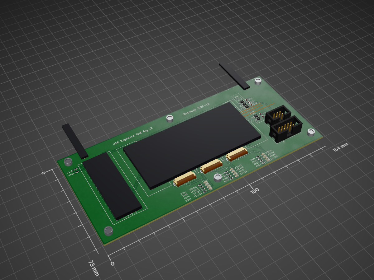
TestRig PCB is an open-source printed circuit board by RasmusB, from the RasmusB/USB-Keyboard-Adapter repository on GitHub. It is a 2-layer board of 164 × 73 mm with 95 parts on 151 nets, routed with 824 tracks and 100 vias.
It is built around the TS5A3357DCU and TCA6424ARGJ. Its parts include 25 resistors, 12 diodes, 11 capacitors, 8 ICs and 5 connectors. It belongs with the keyboards and input boards and the STM32 and AVR (ATmega, ATtiny) boards of this library.


An ATmega32u4 based keyboard controller. This was designed for use with a Psion Series 5mx keyboard, but should work for other keyboards also.
| Qty | Value | Footprint | References |
|---|---|---|---|
| 12 | 270R | Resistor_SMD:R_0603_1608Metric | R204, R205, R206, R207, R404, R405, R406, R407, R504, R505, R506, R507 |
| 11 | 100n | Capacitor_SMD:C_0603_1608Metric | C201, C202, C301, C302, C303, C304, C305, C401, C402, C501, C502 |
| 6 | 10k 1% | Resistor_SMD:R_0603_1608Metric | R201, R202, R401, R402, R501, R502 |
| 6 | M3 | MountingHole:MountingHole_3.2mm_M3 | H101, H102, H103, H104, H105, H106 |
| 5 | 4k7 | Resistor_SMD:R_0603_1608Metric | R101, R102, R203, R403, R503 |
| 5 | TS5A3357 | Package_SO:VSSOP-8_2.3x2mm_P0.5mm | U301, U302, U303, U304, U305 |
| 3 | DUT_CONN | Connector_FFC-FPC:Hirose_FH12-22S-0.5SH_1x22-1MP_P0.50mm_Horizontal | J201, J401, J501 |
| 3 | DUT_OUTLINE | USB-Keyboard:USB_KEYBOARD_ADAPTER_V1.22_DUMMY | DUT201, DUT401, DUT501 |
| 3 | GND | Pogo:Pogo_P50_Bottom | TP207, TP407, TP507 |
| 3 | GRN | LED_SMD:LED_0603_1608Metric | LED204, LED404, LED504 |
| 3 | MISO | Pogo:Pogo_P50_Bottom | TP204, TP404, TP504 |
| 3 | MOSI | Pogo:Pogo_P50_Bottom | TP203, TP403, TP503 |
| 3 | ORNG | LED_SMD:LED_0603_1608Metric | LED202, LED402, LED502 |
| 3 | RED | LED_SMD:LED_0603_1608Metric | LED201, LED401, LED501 |
| 3 | RESET | Pogo:Pogo_P50_Bottom | TP201, TP401, TP501 |
| 3 | SCK | Pogo:Pogo_P50_Bottom | TP202, TP402, TP502 |
| 3 | TCA6424A | Package_DFN_QFN:QFN-32-1EP_5x5mm_P0.5mm_EP3.1x3.1mm | U201, U401, U501 |
| 3 | VBUS | Pogo:Pogo_P50_Bottom | TP206, TP406, TP506 |
| 3 | VTARGET | Pogo:Pogo_P50_Bottom | TP205, TP405, TP505 |
| 3 | YLW | LED_SMD:LED_0603_1608Metric | LED203, LED403, LED503 |
| 2 | 10k | Resistor_SMD:R_0603_1608Metric | R103, R104 |
| 2 | eC_REG | PCB Extras:eC-Registration | REG101, REG102 |
| 1 | AVR-ISP-10 | Connector_IDC:IDC-Header_2x05_P2.54mm_Vertical | J102 |
| 1 | AVR-ISP-6 | Connector_IDC:IDC-Header_2x03_P2.54mm_Vertical | J101 |
| 1 | STM32_BLUE_PILL | BluePill:STM32F103C8T6-ARM-BOARD | MOD101 |
| 1 | TEST_JIG | USB-Keyboard:TestJig | JIG_OUTLINE_1 |

cracked-machine/FunctionGeneratorCortexM4_HW
A function generator powered by ARM Cortex M4

azonenberg/stm32mp2-baremetal-tests
Experimenting with bare metal STM32MP2 development


azonenberg/starshipraider
Open hardware test equipment


azonenberg/latentred
Open hardware 48x 1000baseT + 2x 25G SFP28 Ethernet switch

azonenberg/misc-devboards
Miscellaneous prototype hardware that wasn't major enough to warrant a dedicated repo

azonenberg/triggercrossbar
Rack mountable crossbar matrix for T&M trigger in/out signals, allowing dynamic reconfiguration of an experiment without recabling
It measures 164 × 73 mm and has 2 copper layers, 1.6 mm thick.
95 parts, built around the TS5A3357DCU and TCA6424ARGJ. The full list of its parts is on this page, with links to each part's symbol and footprint where PCBKit's library has them.
From the RasmusB/USB-Keyboard-Adapter repository on GitHub, at the commit this page was made from: the board is TestRig/v2/TestRig-PCB/TestRig-PCB.kicad_pcb and its schematic PCB/Keyboard.kicad_sch. PCBKit opens the board in the browser, with nothing to install.
Its repository states no licence, so its author keeps all rights: ask RasmusB before reusing the design.
