2 layers350 × 70 mm
Rack Front Panel
BayLibre/Labrack
A standard 1U rack front panel metal sheet and PCB providing power, connectivity and more.
50 parts1

 RICCIARDI-Adrien/Power_Button_Press_Automation
A fully analog circuit to simulate a power button press.
Power Button Press Automation is an open-source printed circuit board by RICCIARDI-Adrien, from the RICCIARDI-Adrien/Power_Button_Press_Automation repository on GitHub, published under the MIT licence. It is a 2-layer board of 20 × 30 mm with 18 parts on 9 nets, routed with 50 tracks and 12 vias.
It is built around the LM393DT, BSS138 and TBC05-02-1-G-G. Its parts include 7 resistors, 4 capacitors, 2 transistors, 2 connectors and 1 IC.


A fully analog circuit that activates an open-drain transistor for 1.5s after having waited 3s for the power supply to stabilize.
The timings can be adjusted by changing the RC circuits component values.
It is currently designed for a 12V power supply and can drive any power switch from 1.8V onwards.
The circuit will rearm itself only when the board 12V is removed then reapplied. Thus, it is possible to do a software reboot of the PC or powering it off like with a normal power button.
Digital timing diagram :
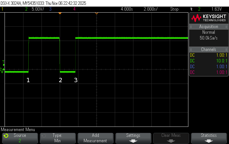
Steps :
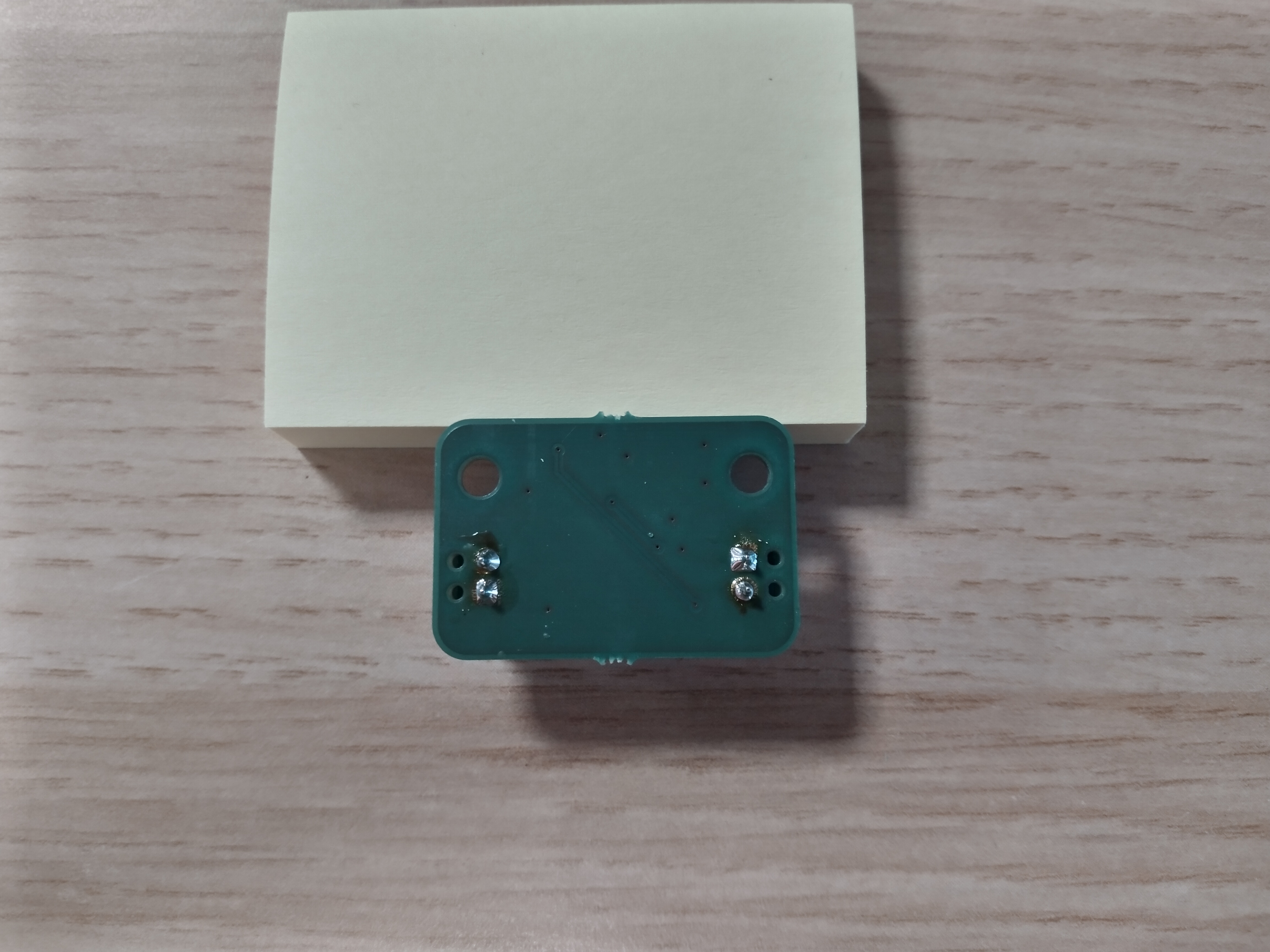
1, the power supply is not present and the button output is kind of floating.1. The button output stays high due to a pull-up connected to the +12V.2.3.Bare PCB :
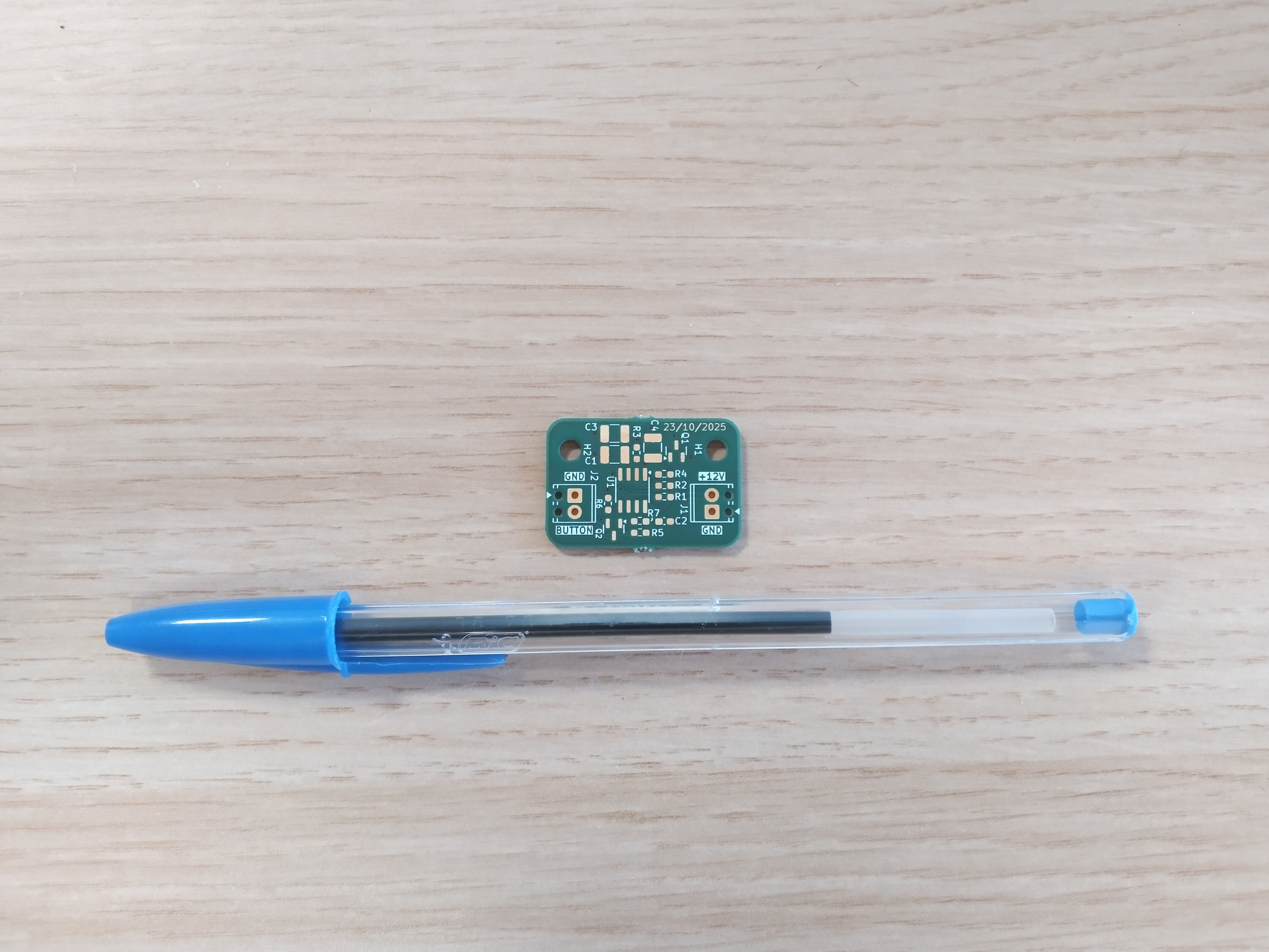
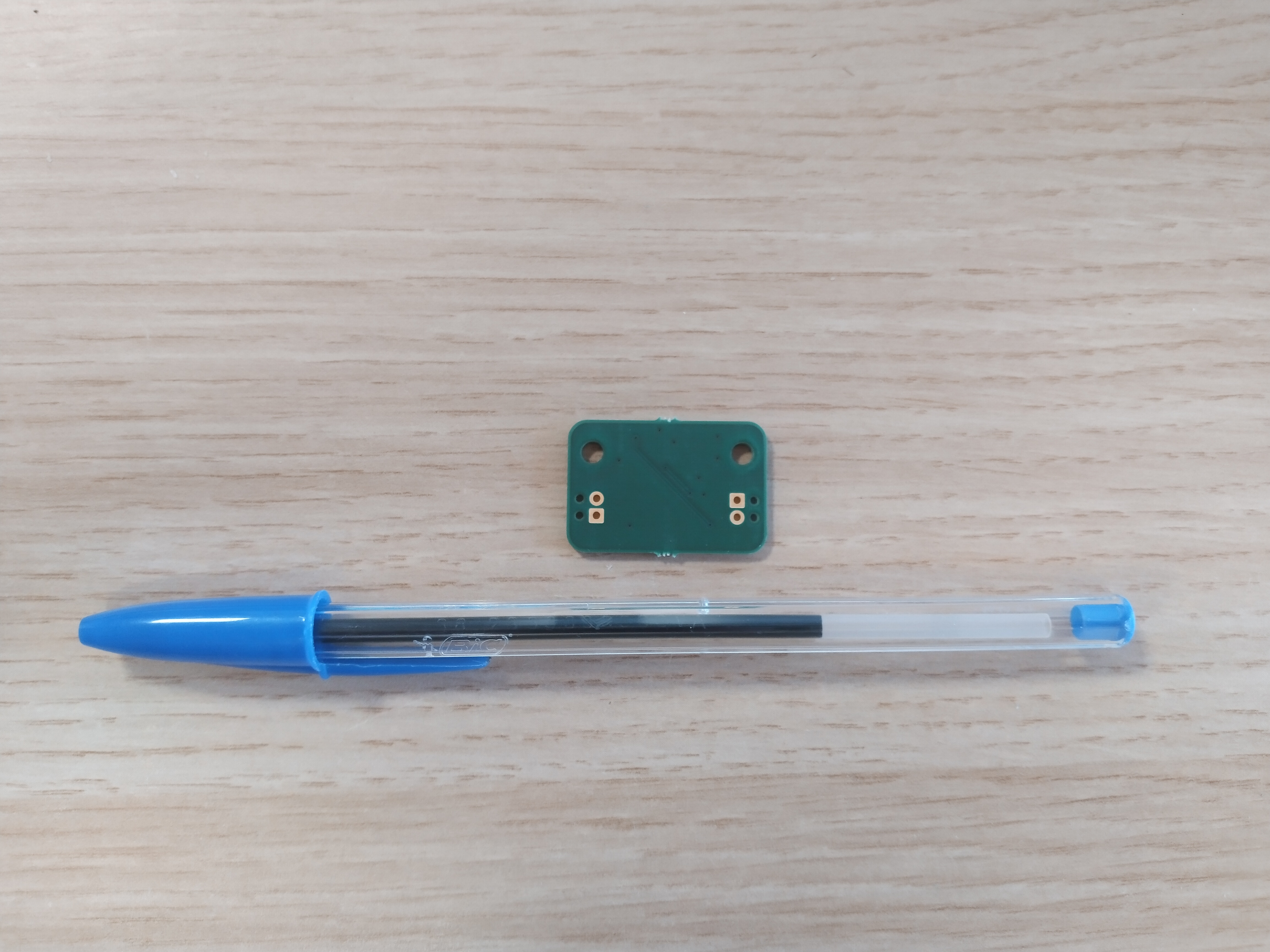
Assembled PCB :
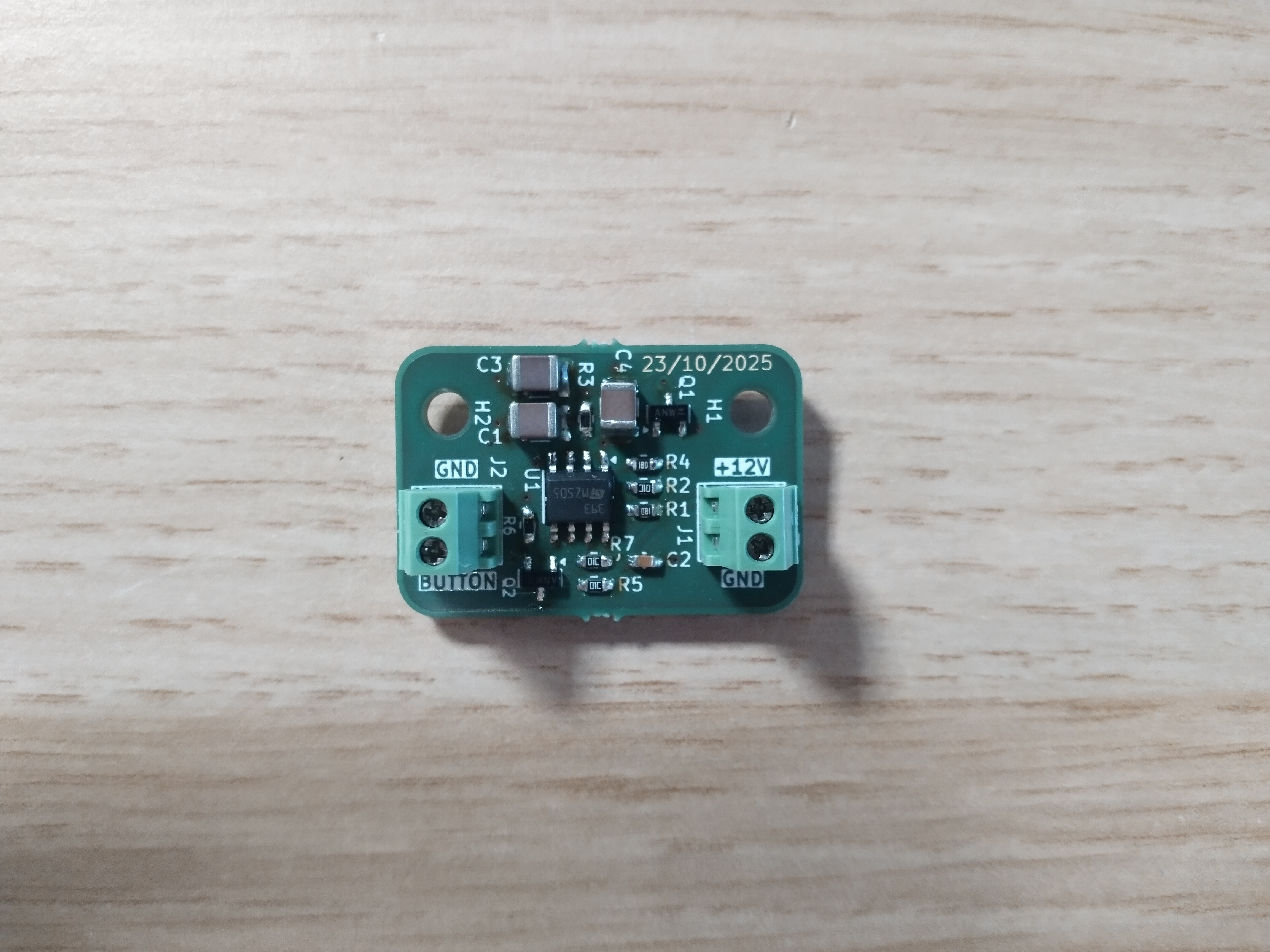
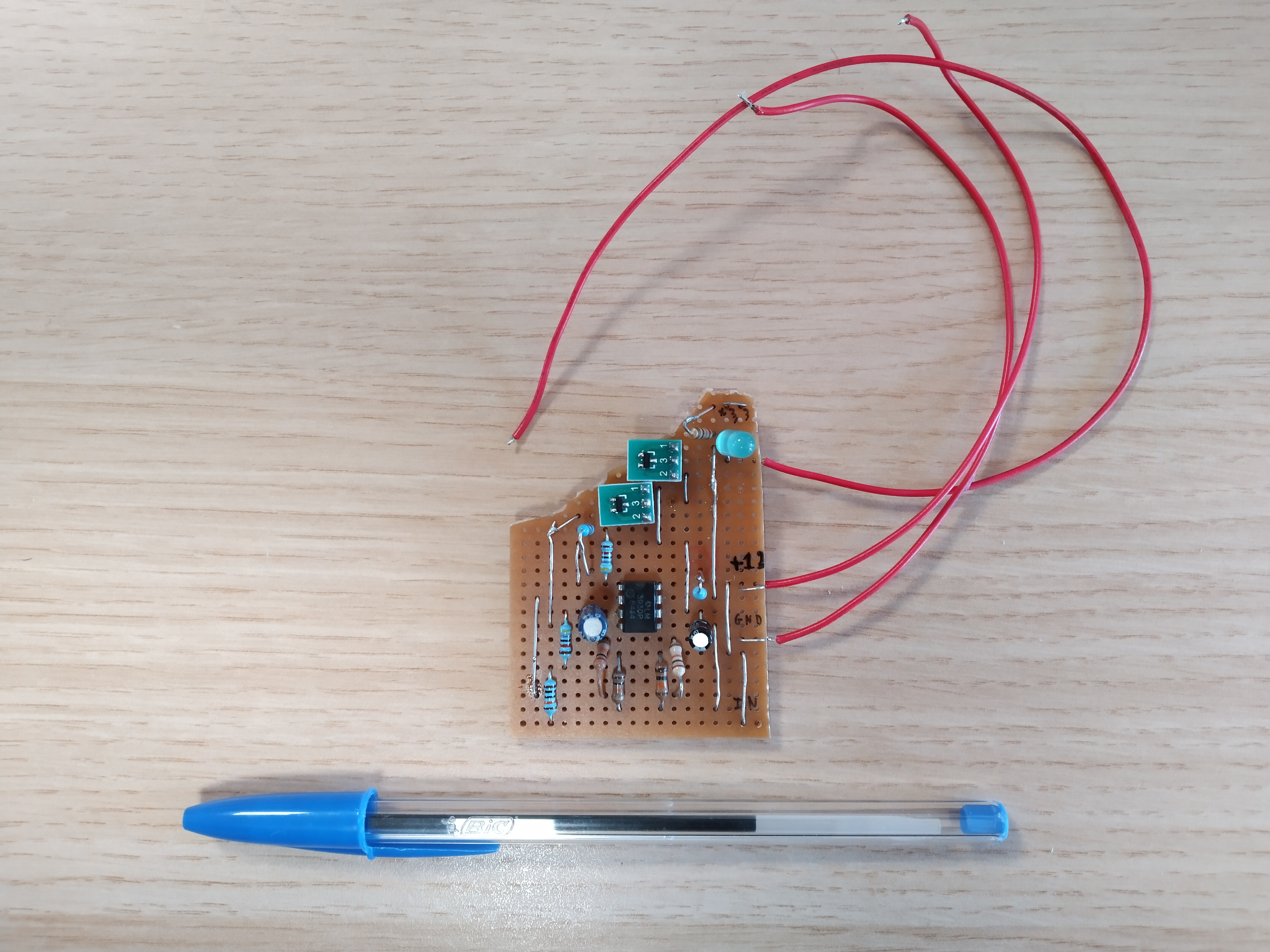
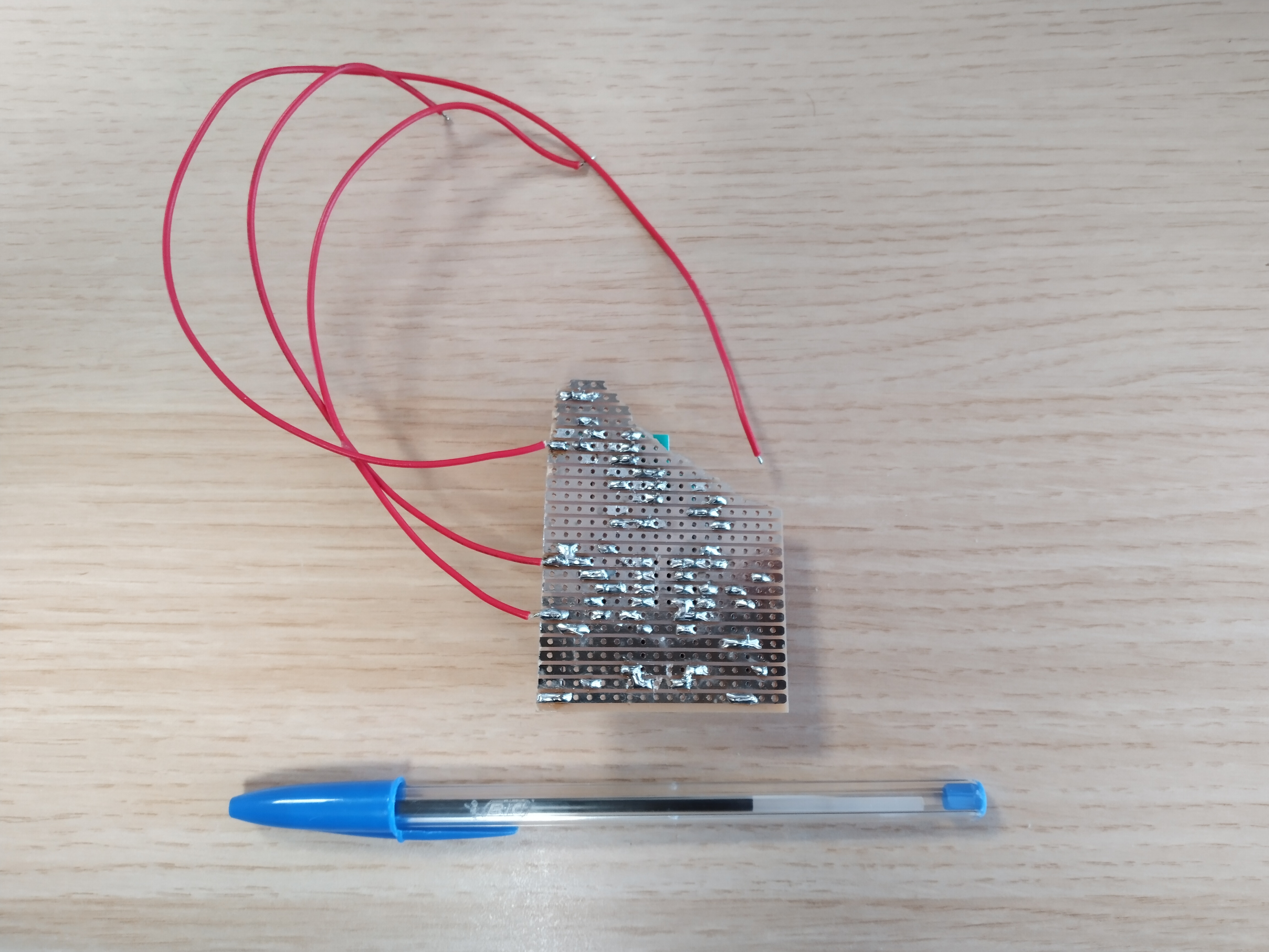
Prototype :
The prototype has been made with recycled parts from old broken machines.
| Qty | Value | Footprint | References |
|---|---|---|---|
| 3 | 10K | Resistor_SMD:R_0603_1608Metric_Pad0.98x0.95mm_HandSolder | R2, R5, R7 |
| 3 | 10u | Capacitor_SMD:C_1210_3225Metric_Pad1.33x2.70mm_HandSolder | C1, C3, C4 |
| 2 | 150K | Resistor_SMD:R_0603_1608Metric_Pad0.98x0.95mm_HandSolder | R1, R4 |
| 2 | 18K | Resistor_SMD:R_0603_1608Metric_Pad0.98x0.95mm_HandSolder | R3, R6 |
| 2 | BSS138 | Package_TO_SOT_SMD:SOT-23 | Q1, Q2 |
| 2 | MountingHole | MountingHole:MountingHole_3.2mm_M3 | H1, H2 |
| 2 | TBC05-02-1-G-G | TerminalBlock_Phoenix:TerminalBlock_Phoenix_MPT-0,5-2-2.54_1x02_P2.54mm_Horizontal | J1, J2 |
| 1 | 100n | Capacitor_SMD:C_0603_1608Metric_Pad1.08x0.95mm_HandSolder | C2 |
| 1 | LM393DT | Package_SO:SOIC-8_3.9x4.9mm_P1.27mm | U1 |
BayLibre/Labrack
A standard 1U rack front panel metal sheet and PCB providing power, connectivity and more.

jdelgranchio/haptic-linear-slider
A PCB for a motorized, haptic linear slider. An RP2354 (RP2350 with built-in flash) drives a Bourns PSM01 motorized slide potentiometer through a DRV8876 H-bridge.


ageppert/Core16-Interactive-Core-Memory
Weave 16 bits of core memory and LEDs to interact with using a magnetic wand


ageppert/Core-64-Interactive-Core-Memory-Badge
64 bits of core memory and LEDs to interact with directly using a magnetic wand.

It measures 20 × 30 mm and has 2 copper layers, 1.6 mm thick.
18 parts, built around the LM393DT, BSS138 and TBC05-02-1-G-G. The full list of its parts is on this page, with links to each part's symbol and footprint where PCBKit's library has them.
From the RICCIARDI-Adrien/Power_Button_Press_Automation repository on GitHub, at the commit this page was made from: the board is Hardware/Power_Button_Press_Automation.kicad_pcb and its schematic Hardware/Power_Button_Press_Automation.kicad_sch. PCBKit opens the board in the browser, with nothing to install.
Its repository publishes it under the MIT licence: you may reuse it on that licence's terms (keep the author's notice, and for a copyleft licence share your changes alike).