2 layers84.3 × 57.5 mm

 PituePao/three-phase-power-meter
Three-phase energy meter (ESP32-C3 + ATM90E36A) with MQTT/Home Assistant integration
Misuratore potenza is an open-source printed circuit board by PituePao, from the PituePao/three-phase-power-meter repository on GitHub, published under the MIT licence. It is a 2-layer board of 100 × 100 mm with 108 parts on 91 nets, routed with 561 tracks and 88 vias.
It is built around the ATM90E36A-AU-R, AMS1117-3.3 and XF2M-2015-1A. Its parts include 55 resistors, 29 capacitors, 5 diodes, 4 ICs and 3 connectors. It belongs with the home automation and IoT boards and the ESP32 and RISC-V boards of this library.


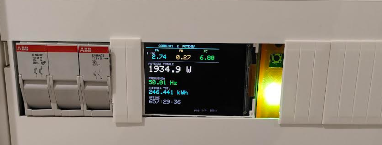
A custom three-phase energy meter based on the ATM90E36A metering IC and ESP32-C3, designed for real-time monitoring and Home Assistant integration.
This project is a complete three-phase energy monitoring solution designed from scratch, including hardware, firmware and PCB development.
The system measures electrical parameters from a three-phase network and publishes the collected data over MQTT, allowing seamless integration with Home Assistant.
The project includes:
| Component | Description |
|---|---|
| MCU | ESP32-C3 SuperMini |
| Metering IC | ATM90E36A |
| Display | ST7789 240x240 TFT |
| Current Sensors | Current Transformers |
| Voltage Measurement | Resistor Divider |
| Communication | SPI |
| Connectivity | WiFi |
The firmware has been developed in C/C++ using the Arduino framework.
Main software modules:
                   +-------------------------+
                   |      Three Phase Grid   |
                   +------------+------------+
                                |
                    Voltage & Current
                                |
                                ▼
                      +-----------------+
                      |   ATM90E36A     |
                      | Energy Meter IC |
                      +--------+--------+
                               |
                              SPI
                               |
                               ▼
                     +------------------+
                     |    ESP32-C3      |
                     +--------+---------+
                              |
          +-------------------+------------------+
          |                   |                  |
          ▼                   ▼                  ▼
     TFT Display          MQTT Broker        OTA Update
                               |
                               ▼
Home AssistantThe PCB has been entirely designed in KiCad.
Main design considerations:
| Top | Bottom |
|---|---|
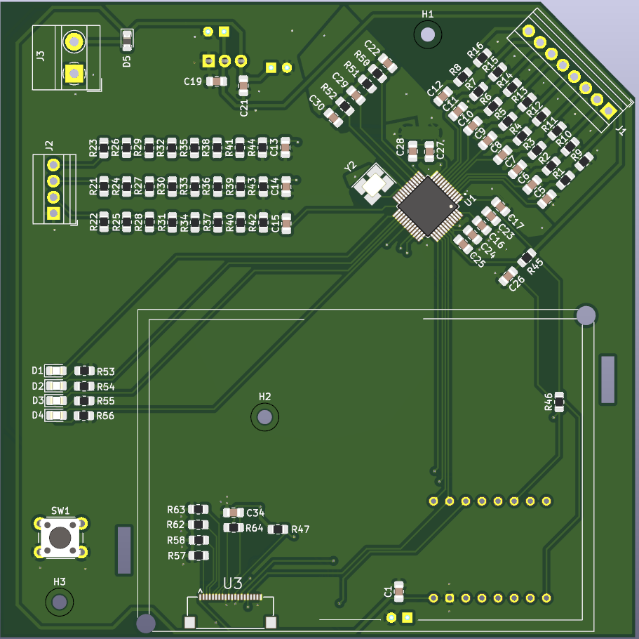 | 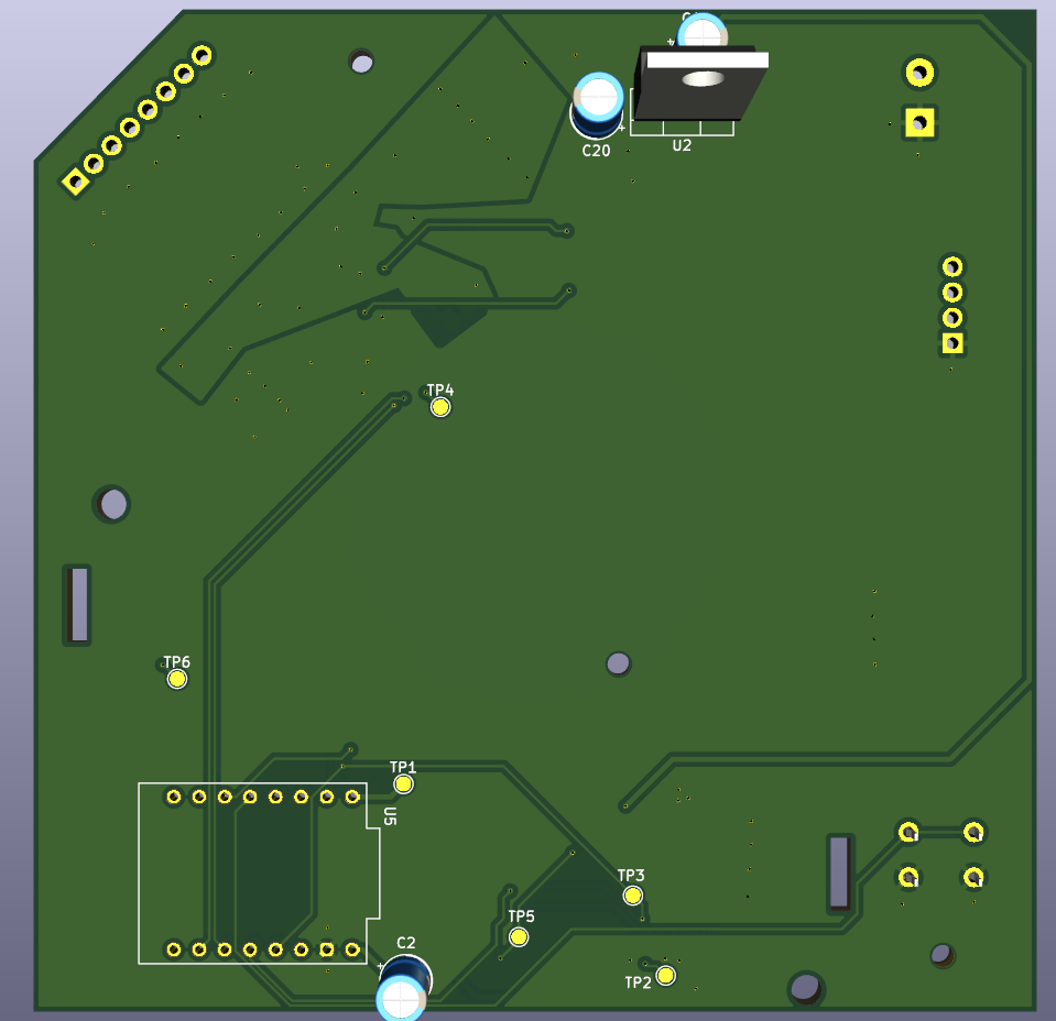 |
main()

│

├── WiFi Manager

├── MQTT Manager

├── Display Manager

├── Meter Driver

├── Configuration

└── OTA UpdateThe firmware automatically publishes MQTT Discovery messages.
Available sensors include:
During development several technical challenges were addressed:
Current status:
.
├── datasheet/
├── libraries/
├── hardware/
├── firmware/
├── docs/
│   └── images/
└── README.mdThis project is released under the MIT License.
| Qty | Value | Footprint | References |
|---|---|---|---|
| 21 | 220k | Resistor_SMD:R_0805_2012Metric_Pad1.20x1.40mm_HandSolder | R21, R22, R23, R24, R25, R26, R27, R28, R29, R30, R31, R32, R33, R34, R35, R36 +5 |
| 14 | 1k | Resistor_SMD:R_0805_2012Metric_Pad1.20x1.40mm_HandSolder | R1, R2, R3, R4, R5, R6, R7, R8, R42, R43, R44, R50, R51, R52 |
| 11 | 18n | Capacitor_SMD:C_0805_2012Metric_Pad1.18x1.45mm_HandSolder | C5, C6, C7, C8, C9, C10, C11, C12, C13, C14, C15 |
| 8 | 10R | Resistor_SMD:R_0805_2012Metric_Pad1.20x1.40mm_HandSolder | R9, R10, R11, R12, R13, R14, R15, R16 |
| 6 | TestPoint | TestPoint:TestPoint_Pad_D1.5mm | TP1, TP2, TP3, TP4, TP5, TP6 |
| 5 | 0.1uF | Capacitor_SMD:C_0805_2012Metric_Pad1.18x1.45mm_HandSolder | C16, C17, C24, C26, C27 |
| 4 | 150R | Resistor_SMD:R_0805_2012Metric_Pad1.20x1.40mm_HandSolder | R57, R58, R62, R63 |
| 4 | 18nF | Capacitor_SMD:C_0805_2012Metric_Pad1.18x1.45mm_HandSolder | C22, C29, C30, C34 |
| 4 | 510R | Resistor_SMD:R_0805_2012Metric_Pad1.20x1.40mm_HandSolder | R53, R54, R55, R56 |
| 4 | LED | LED_SMD:LED_0805_2012Metric_Pad1.15x1.40mm_HandSolder | D1, D2, D3, D4 |
| 3 | 100n | Capacitor_SMD:C_0805_2012Metric_Pad1.18x1.45mm_HandSolder | C1, C19, C21 |
| 3 | 10K | Resistor_SMD:R_0805_2012Metric_Pad1.20x1.40mm_HandSolder | R46, R47, R64 |
| 3 | 10uF | Capacitor_SMD:C_0805_2012Metric_Pad1.18x1.45mm_HandSolder | C23, C25, C28 |
| 3 | 10uF | Capacitor_THT:CP_Radial_D5.0mm_P2.50mm | C2, C18, C20 |
| 3 | MountingHole | MountingHole:MountingHole_2.2mm_M2 | H1, H2, H3 |
| 1 | 10k | Resistor_SMD:R_0805_2012Metric_Pad1.20x1.40mm_HandSolder | R45 |
| 1 | AMS1117-3.3 | Package_TO_SOT_THT:TO-220-3_Vertical | U2 |
| 1 | ATM90E36A-AU-R | ATM90E36A:QFP50P900X900X120-48N | U1 |
| 1 | Crystal_GND24 | Crystal:Crystal_SMD_3225-4Pin_3.2x2.5mm_HandSoldering | Y2 |
| 1 | D_Schottky | Diode_SMD:D_0805_2012Metric_Pad1.15x1.40mm_HandSolder | D5 |
| 1 | ESP32-C3_SUPERMINI_TH | ESP32-C3_SUPERMINI_TH:MODULE_ESP32-C3_SUPERMINI_TH | U5 |
| 1 | NetTie_2 | NetTie:NetTie-2_SMD_Pad2.0mm | NT1 |
| 1 | SW_Push | Button_Switch_THT:SW_PUSH_6mm | SW1 |
| 1 | Screw_Terminal_01x02 | TerminalBlock_MetzConnect:TerminalBlock_MetzConnect_Type011_RT05502HBWC_1x02_P5.00mm_Horizontal | J3 |
| 1 | Screw_Terminal_01x04 | TerminalBlock:TerminalBlock_Xinya_XY308-2.54-4P_1x04_P2.54mm_Horizontal | J2 |
| 1 | Screw_Terminal_01x08 | TerminalBlock:TerminalBlock_Xinya_XY308-2.54-8P_1x08_P2.54mm_Horizontal | J1 |
| 1 | XF2M-2015-1A | XF2M-2015-1A:OMRON_XF2M-2015-1A | U3 |


pascallanger/DIY-Multiprotocol-TX-Module
Multiprotocol TX Module (or MULTI-Module) is a 2.4GHz transmitter module which controls many different receivers and models.

fossasia/pslab-hardware
PSLab Hardware Design and Schematics https://pslab.io


MaltWhiskey/Mega-Cube
16x16x16 PL9823 Cube with Teensy 4.0 and FlexIO driver

It measures 100 × 100 mm and has 2 copper layers, 1.6 mm thick.
108 parts, built around the ATM90E36A-AU-R, AMS1117-3.3 and XF2M-2015-1A. The full list of its parts is on this page, with links to each part's symbol and footprint where PCBKit's library has them.
From the PituePao/three-phase-power-meter repository on GitHub, at the commit this page was made from: the board is hardware/misuratore_potenza.kicad_pcb and its schematic hardware/input_output.kicad_sch. PCBKit opens the board in the browser, with nothing to install.
Its repository publishes it under the MIT licence: you may reuse it on that licence's terms (keep the author's notice, and for a copyleft licence share your changes alike).