
4 layers128.3 × 97.8 mm
 PHS-SMCS/SMCSKart-Mainboard1
Documentation for the SMCSKart PCB
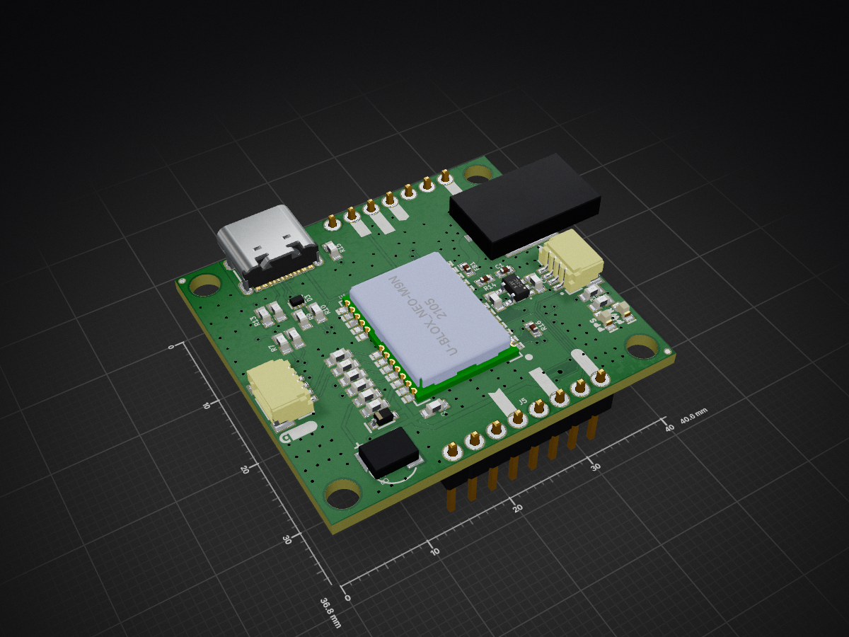
SparkFun GPS NEO M9N SMA is an open-source printed circuit board by PHS-SMCS, from the PHS-SMCS/SMCSKart-Mainboard repository on GitHub. It is a 2-layer board of 40.6 × 36.8 mm with 94 parts on 36 nets, routed with 359 tracks and 246 vias.
It is built around the PRTR5V0U2F. Its parts include 16 resistors, 6 connectors, 5 capacitors, 4 diodes and 2 ICs. It belongs with the radio and wireless and robots and motor control boards of this library.
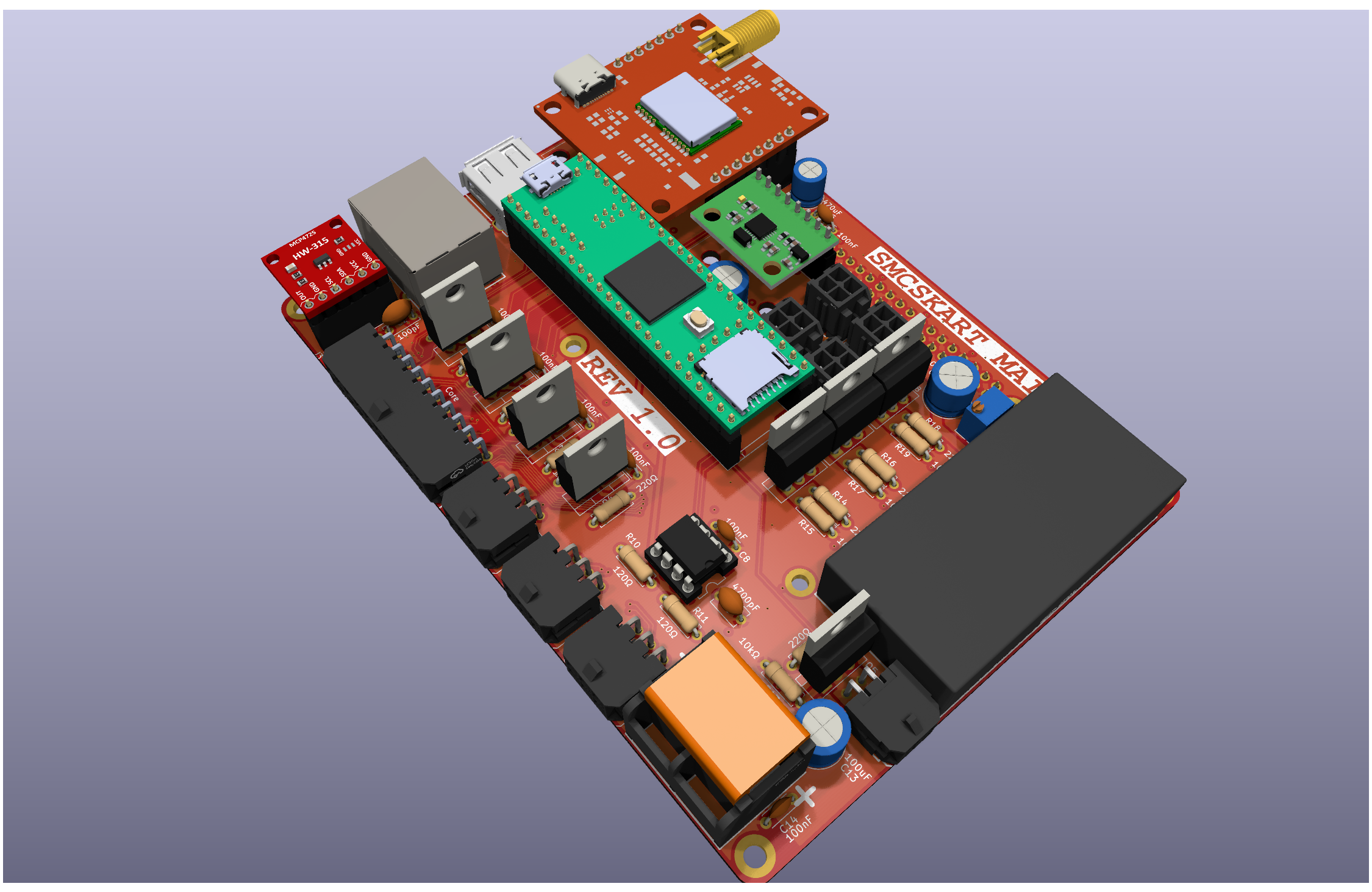
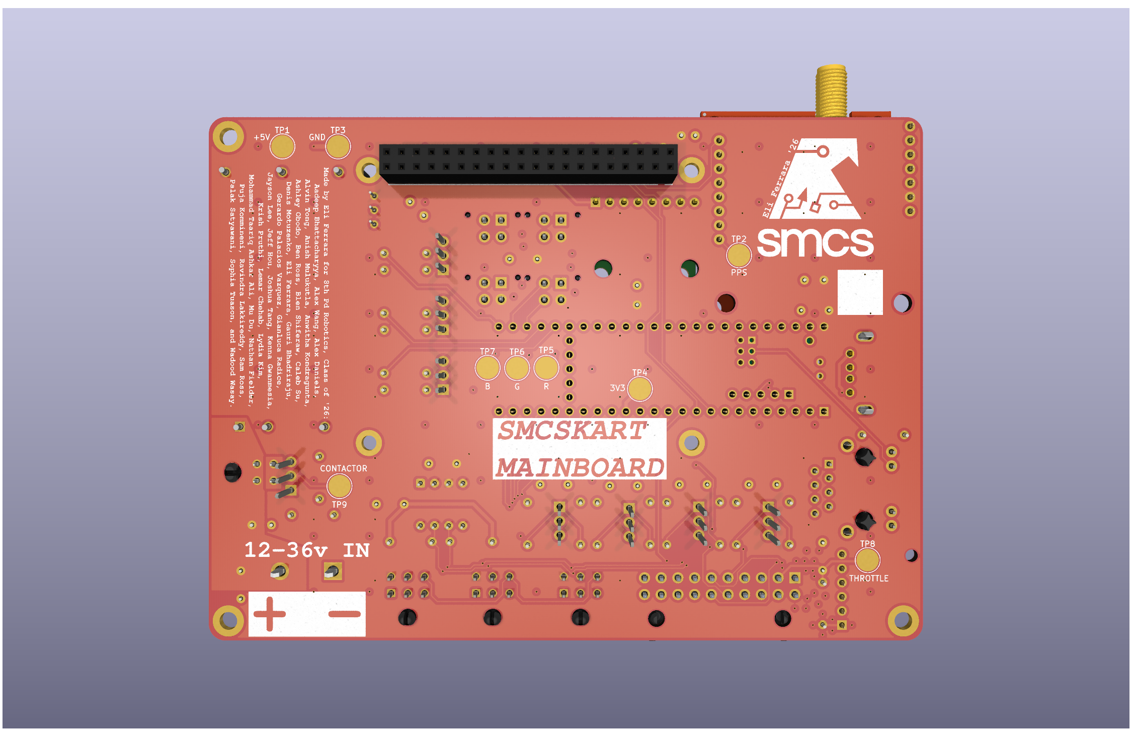
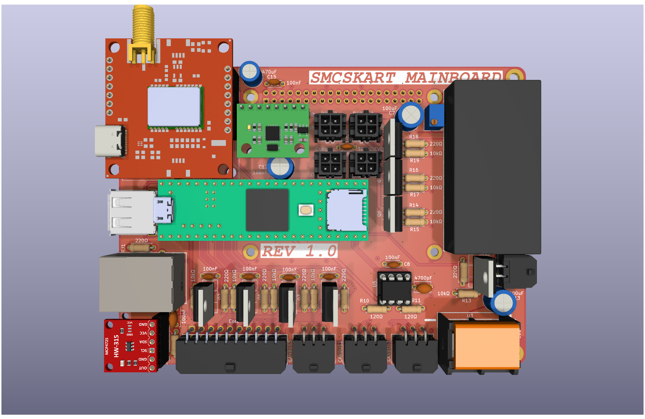
Custom PCB integrating every system in the SMCS Robotics 8th period go-kart. The board acts as the central hub between a Raspberry Pi 4, a Teensy 4.1, all motor controller I/O, sensors, and peripherals.
| Component | Description |
|---|---|
| Raspberry Pi 4 | Main compute; connected via 40-pin header |
| Teensy 4.1 | Real-time microcontroller with onboard Ethernet |
| NEO-M9N | GPS module (connected to Pi I2C + PPS to Teensy) |
| MPU6050 | 6-axis accelerometer/gyroscope (connected to Pi I2C) |
| MCP4725 | 12-bit DAC for throttle signal generation (connected to Teensy I2C) |
| MCP2562-E/P | CAN bus transceiver |
| IRLZ44N | Logic-level N-channel MOSFETs for all toggle/switch outputs (with pulldown resistors) |
| ND721000 | FarDriver BLDC/PMSM speed controller (RS232 interface) |
The board supplies three voltage rails available on the extra power port:
| Rail | Voltage |
|---|---|
| 3V3 | 3.3 V |
| 5V | 5 V |
| 24V | 24 V (also used for LED strip) |
| Pin(s) | Interface | Connected To | Notes |
|---|---|---|---|
| 0, 1 | Serial1 (TX, RX) | ND721000 ESC | RS232 level — programming/telemetry port on ESC |
| 7, 8 | Serial2 (TX, RX) | Raspberry Pi 4 | UART bridge between Teensy and Pi |
| 14, 15 | Serial3 (TX, RX) | Transceiver module | RF/wireless transceiver comms |
| 34, 35 | Serial8 (TX, RX) | FPV camera | UART control for FPV camera |
| Pin(s) | Bus | Connected To |
|---|---|---|
| 18, 19 | SDA, SCL | MCP4725 DAC (throttle control) |
| Pin(s) | Signal | Notes |
|---|---|---|
| 30, 31 | CRX, CTX | Via MCP2562-E/P transceiver; 120 Ω termination required at each end |
All toggle output pins drive an IRLZ44N MOSFET with a pulldown resistor, providing an active-low ground signal to the ESC connector.
| Pin | Function | ESC Signal | Direction |
|---|---|---|---|
| 2 | Hall Pulses input | Hall Pulses (ESC pin 18) | Input from ESC |
| 3 | Reverse toggle | REV (ESC pin 8) | Output to ESC |
| 4 | Brake toggle | Low Brake (ESC pin 21) | Output to ESC |
| 5 | High speed toggle | High Speed (ESC pin 3) | Output to ESC |
| 6 | Low speed toggle | Low Speed (ESC pin 2) | Output to ESC |
| 9 | Cruise control | Cruise/Boost connector | Output to ESC |
| 10 | PPS | NEO-M9N GPS pulse-per-second | Input from GPS |
| 32 | Contactor toggle | Main contactor relay | Output |
| Pin | Channel |
|---|---|
| 37 | Red |
| 36 | Green |
| 33 | Blue |
| Pin | Label |
|---|---|
| 25 | EX1 |
| 26 | EX2 |
| 27 | EX3 |
| 28 | EX4 |
| 29 | EX5 |
| Device | Address | Function |
|---|---|---|
| NEO-M9N | — | GPS module |
| MPU6050 | 0x68 | Accelerometer / Gyroscope |
The Teensy communicates with the ND721000 over Serial1 (pins 0/1) at RS232 levels (programming/telemetry port). In addition, discrete signals are routed between the board and the ESC's connector harness.
| ESC Pin | Color | Signal | Direction | Teensy Pin | Notes |
|---|---|---|---|---|---|
| 1 | Yellow | Hall A | → ESC | — | Motor hall sensor A |
| 2 | Blue-White | Low Speed | ← Teensy | 6 | Ground to activate low speed profile |
| 3 | Yellow-White | High Speed | ← Teensy | 5 | Ground to activate high speed profile |
| 4 | Red | HALL+ | — | — | ~14 V supply to hall sensors / encoder |
| 5 | Brown-Yellow | CAN L | ↔ | — | CAN bus low (optional; 120 Ω termination required) |
| 6 | Black | GND (Hall) | — | — | Hall sensor ground |
| 7 | Black | B− / GND | — | — | Battery negative / signal ground |
| 8 | Brown-White | REV | ← Teensy | 3 | Ground to request reverse direction |
| 9 | Purple | Speedometer signal | → | — | Analog speed output for speedometer gauge |
| 10 | Orange | Key | — | — | Main power-on input (connect to key switch via 5A fuse) |
| 11 | Gray | High Brake | ← Teensy | 4 | Active-high (12 V) brake input |
| 12 | Green | Hall B | → ESC | — | Motor hall sensor B |
| 13 | Light-Blue | SPD (digital speed pulse) | → | — | Square-wave RPM output for digital speedo / ECU |
| 14 | Black-White | FW (anti-theft) | ← | — | Ground to activate anti-theft lockout (error code 6) |
| 15 | Red-Yellow | CAN H | ↔ | — | CAN bus high (optional; 120 Ω termination required) |
| 16 | Black | GND (serial/switch) | — | — | Signal ground for serial and switch circuits |
| 17 | White | Hall P (encoder index) | → ESC | — | Once-per-revolution encoder reference pulse |
| 18 | Brown | Hall Pulses signal | → Teensy | 2 | Speed pulse output used as tachometer reference |
| 19 | Brown-Red | Lock Phase | — | — | Anti-theft motor phase lock wire |
| 20 | Orange | Key (anti-theft) | — | — | Secondary key input for anti-theft subsystem |
| 21 | Yellow-Green | Low Brake | ← Teensy | 4 | Active-low brake input; ground to signal braking |
| 22 | Blue | Hall C | → ESC | — | Motor hall sensor C |
| 23 | Brown-Blue | TxD (serial) | → Teensy | 0 (RX) | ESC serial transmit → Teensy Serial1 RX |
| 24 | White | Motor Temp | → ESC | — | Motor temperature sensor (PTC/NTC/KTY) |
| 25 | — | — | — | — | — |
| 26 | Black | GND (throttle/brake) | — | — | Shared signal ground for throttle and brake circuits |
| 27 | Green-White | TPS (throttle) | ← DAC | — | Throttle position signal (0.5–4.3 V); driven by MCP4725 |
| 28 | Red-White | ACC+ (5 V) | → throttle sensor | — | 5 V regulated supply for throttle sensor |
| 29 | Brown-Green | V+ (serial power) | → adapter | — | 5 V supply for USB-TTL programming adapter |
| 30 | Pink | B+ (anti-theft) | — | — | Always-live battery positive for anti-theft device |
| 31 | Brown-Red | RxD (serial) | ← Teensy | 1 (TX) | ESC serial receive ← Teensy Serial1 TX |
Note: High Brake (pin 11) is active-high (12 V) while Low Brake (pin 21) is active-low (GND). Both can signal braking; the board uses pin 21 via MOSFET toggle (Teensy pin 4). Note: Medium speed mode is the ESC default when neither High Speed nor Low Speed is grounded.
| Port | Description |
|---|---|
| 40-pin header | Raspberry Pi 4 HAT connector |
| USB-A | HID peripheral (keyboard, gamepad, etc.) |
| Ethernet | Networking (Teensy 4.1 native Ethernet) |
| CAN × 3 | CANBUS + I2C interface ports |
| Contactor | Trigger port for main contactor relay (Teensy pin 32) |
| FPV camera | UART port (Teensy Serial8, pins 34/35) |
| Transceiver | RF transceiver UART port (Teensy Serial3, pins 14/15) |
| Power port | Extra 3V3 / 5V / 24V supply breakout |
| LED strip | 24 V RGB PWM output (pins 37, 36, 33) |
For images of each port's annotated pinout, see ./docs/PINOUTS.md
Made by Eli Ferrara, SMCS Class of 2026 MIT License
| Qty | Value | Footprint | References |
|---|---|---|---|
| 4 | SparkFun GPS NEO_M9N_SMA:#3V3#6 | U$4, U$5, U$39, U$40 | |
| 4 | SparkFun GPS NEO_M9N_SMA:#GND#0 | U$7, U$8, U$38, U$41 | |
| 4 | 33 | SparkFun GPS NEO_M9N_SMA:0603 | R2, R3, R4, R6 |
| 4 | FIDUCIALUFIDUCIAL | SparkFun GPS NEO_M9N_SMA:MICRO-FIDUCIAL | JP21, JP61, JP71, JP81 |
| 4 | STAND-OFF | SparkFun GPS NEO_M9N_SMA:STAND-OFF | JP1, JP31, JP91, JP101 |
| 3 | 1.0uF | SparkFun GPS NEO_M9N_SMA:0603 | C3, C4, C6 |
| 3 | 1k | SparkFun GPS NEO_M9N_SMA:0603 | R1, R5, R11 |
| 2 | SparkFun GPS NEO_M9N_SMA:1X04_NO_SILK | J5, JP15 | |
| 2 | SparkFun GPS NEO_M9N_SMA:#PPS#13 | U$11, U$32 | |
| 2 | SparkFun GPS NEO_M9N_SMA:#5V#1 | U$6, U$42 | |
| 2 | 2.2k | SparkFun GPS NEO_M9N_SMA:0603 | R7, R8 |
| 2 | 27 | SparkFun GPS NEO_M9N_SMA:0603 | R9, R10 |
| 2 | 5.1k | SparkFun GPS NEO_M9N_SMA:0603 | R12, R13 |
| 2 | JUMPER-SMT_2_NC_TRACE_SILK | SparkFun GPS NEO_M9N_SMA:SMT-JUMPER_2_NC_TRACE_SILK | PPS0, PWR\0 |
| 2 | Qwiic Right Angle | SparkFun GPS NEO_M9N_SMA:JST04_1MM_RA | J2, J4 |
| 1 | SparkFun GPS NEO_M9N_SMA:#SCK#12 | U$16 | |
| 1 | SparkFun GPS NEO_M9N_SMA:##CS##6 | U$26 | |
| 1 | SparkFun GPS NEO_M9N_SMA:##RST##12 | U$27 | |
| 1 | SparkFun GPS NEO_M9N_SMA:U#BLOX19 | U$2 | |
| 1 | SparkFun GPS NEO_M9N_SMA:#RX#SDI#10 | U$15 | |
| 1 | SparkFun GPS NEO_M9N_SMA:ANT8 | U$24 | |
| 1 | SparkFun GPS NEO_M9N_SMA:#RX#SDI#4 | U$33 | |
| 1 | SparkFun GPS NEO_M9N_SMA:#SCL#18 | U$18 | |
| 1 | SparkFun GPS NEO_M9N_SMA:QWIIC_4MM | U$14 | |
| 1 | SparkFun GPS NEO_M9N_SMA:NEO#M9N20 | U$25 | |
| 1 | SparkFun GPS NEO_M9N_SMA:#SCK#3 | U$34 | |
| 1 | SparkFun GPS NEO_M9N_SMA:#INT#10 | U$30 | |
| 1 | SparkFun GPS NEO_M9N_SMA:L1#L28 | U$23 | |
| 1 | SparkFun GPS NEO_M9N_SMA:##SAFE##15 | U$3 | |
| 1 | SparkFun GPS NEO_M9N_SMA:#PWR#1 | U$17 | |
| 1 | SparkFun GPS NEO_M9N_SMA:#I2C#3 | U$29 | |
| 1 | SparkFun GPS NEO_M9N_SMA:USB-C-16P-2LAYER-PADS | J3 | |
| 1 | SparkFun GPS NEO_M9N_SMA:NEO_GPS_BOARD_SILK_FINAL#03#JPG | U$21 | |
| 1 | SparkFun GPS NEO_M9N_SMA:PWR6 | U$13 | |
| 1 | SparkFun GPS NEO_M9N_SMA:1X07_NO_SILK | J1 | |
| 1 | SparkFun GPS NEO_M9N_SMA:##RST##2 | U$28 | |
| 1 | SparkFun GPS NEO_M9N_SMA:##SAFE##11 | U$22 | |
| 1 | SparkFun GPS NEO_M9N_SMA:#SDA#9 | U$36 | |
| 1 | SparkFun GPS NEO_M9N_SMA:##CS##9 | U$1 | |
| 1 | SparkFun GPS NEO_M9N_SMA:#SPI#22 | U$12 | |
| 1 | SparkFun GPS NEO_M9N_SMA:PPS7 | U$10 | |
| 1 | SparkFun GPS NEO_M9N_SMA:#INT#16 | U$9 | |
| 1 | SparkFun GPS NEO_M9N_SMA:#SDA#17 | U$19 | |
| 1 | SparkFun GPS NEO_M9N_SMA:#TX#SDO#11 | U$20 | |
| 1 | SparkFun GPS NEO_M9N_SMA:#SCL#8 | U$35 | |
| 1 | SparkFun GPS NEO_M9N_SMA:#TX#SDO#5 | U$37 | |
| 1 | SparkFun GPS NEO_M9N_SMA:#PPS#0 | U$31 | |
| 1 | 0.1uF | SparkFun GPS NEO_M9N_SMA:0603 | C5 |
| 1 | 0.5A/40V/420mV | SparkFun GPS NEO_M9N_SMA:SOD-323 | D2 |
| 1 | 100k | SparkFun GPS NEO_M9N_SMA:0603 | R15 |
| 1 | 10k | SparkFun GPS NEO_M9N_SMA:0402 | R16 |
| 1 | 3.3V | SparkFun GPS NEO_M9N_SMA:SOT23-5 | U2 |
| 1 | 33 | SparkFun GPS NEO_M9N_SMA:0402 | R14 |
| 1 | 47pF | SparkFun GPS NEO_M9N_SMA:0402 | C1 |
| 1 | 6.8MM_COIN_CELL | SparkFun GPS NEO_M9N_SMA:ML414H_IV01E | B1 |
| 1 | ANTENNA-GROUNDEDEDGE_SMA_SMD | SparkFun GPS NEO_M9N_SMA:SMA-EDGE-SMD | E1 |
| 1 | BLUE | SparkFun GPS NEO_M9N_SMA:LED-0603 | LED1 |
| 1 | FERRITE_BEAD-120_OHM-0402 | SparkFun GPS NEO_M9N_SMA:0402 | FB1 |
| 1 | FRAME-LETTER | SparkFun GPS NEO_M9N_SMA:CREATIVE_COMMONS | FRAME1 |
| 1 | JUMPER-SMT_2_NO_SILK | SparkFun GPS NEO_M9N_SMA:SMT-JUMPER_2_NO_SILK | SPI0 |
| 1 | JUMPER-SMT_3_2-NC_TRACE_SILK | SparkFun GPS NEO_M9N_SMA:SMT-JUMPER_3_2-NC_TRACE_SILK | JP5 |
| 1 | OSHW-LOGOMINI | SparkFun GPS NEO_M9N_SMA:OSHW-LOGO-MINI | LOGO1 |
| 1 | PRTR5V0U2F | SparkFun GPS NEO_M9N_SMA:SOT886 | D3 |
| 1 | RED | SparkFun GPS NEO_M9N_SMA:LED-0603 | LED2 |
| 1 | SFE_LOGO_NAME_FLAME.1_INCH | SparkFun GPS NEO_M9N_SMA:SFE_LOGO_NAME_FLAME_.1 | LOGO2 |
| 1 | TEST-POINT3X4 | SparkFun GPS NEO_M9N_SMA:PAD.03X.04 | TP1 |
| 1 | U-BLOX_NEO-M9N | SparkFun GPS NEO_M9N_SMA:NEO-M9N_M8T_M8U | U1 |


chenzhuoyu/rainbow-board
ECP5 FPGA breakout board for Colorlight i5 / i9

shaun-lloyd/dev-ardupilot-obal
ArduPi is an open hardware Raspberry Pi hat to run Ardupilot.

oomlout/oomlout_oomp_documentation_bot
a bot that goes around generating rough documentation for kicad projects

Will946/GNSS
u-blox ZED-F9P RTK GNSS breakout board with dual-band L1/L2 reception and centimeter-level positioning accuracy.

Zmotive/HY_550CJ_Control_board
This Project is still under development and not all features have been tested. As I work through the hardware I will continue to update.

HeyPCB/senswear-kicad
Sens Wear's SensWear smart ring hardware, converted from their Altium design to KiCad 10. Design by Sens Wear (github.com/Sens-Wear/hardware), MIT.

It measures 40.6 × 36.8 mm and has 2 copper layers, 1.6 mm thick.
94 parts, built around the PRTR5V0U2F. The full list of its parts is on this page, with links to each part's symbol and footprint where PCBKit's library has them.
From the PHS-SMCS/SMCSKart-Mainboard repository on GitHub, at the commit this page was made from: the board is libs/GPS-17285/SparkFun GPS NEO_M9N_SMA/SparkFun GPS NEO_M9N_SMA.kicad_pcb and its schematic SMCSKart-Mainboard.kicad_sch. PCBKit opens the board in the browser, with nothing to install.
Its repository states no licence, so its author keeps all rights: ask PHS-SMCS before reusing the design.