

4 layers110 × 80 mm
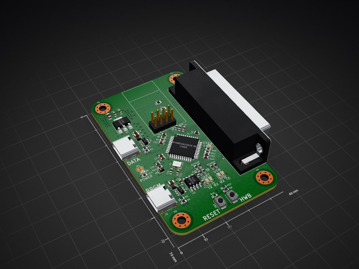
 OpenRetroPad/OpenRetroPadHW2
Custom PCB for OpenRetroPad
OpenRetroPad is an open-source printed circuit board by OpenRetroPad, from the OpenRetroPad/OpenRetroPadHW repository on GitHub. It is a 4-layer board of 46 × 74 mm with 71 parts on 77 nets, routed with 457 tracks and 123 vias.
It is built around the ATMEGA32U4-MU, CH330N and USBLC6-2SC6, with the AMS1117-3.3 among its other parts. Its parts include 20 capacitors, 19 resistors, 9 diodes, 5 ICs and 4 connectors. It belongs with the AVR (ATmega, ATtiny) boards of this library.


This board is based around an ATmega32u4 which is commonly seen on the official Arduino Micro and Leonardo boards. They are also on a fair number of third party Arduino compatible boards known as 'Pro Micro' (e.g. sparkfun's Pro Micro).
The current design includes two USB-C plugs of which both can be used for programming, J2 over a CH330N/CH340N USB-UART serial connection or J1 over USB DFU.
A 2x4 female 2.54mm/0.1in header is also available for an nRF24L01 wireless transceiver module.
Controllers can be connected via a male DB25 mounted on the PCB. The recommended way of doing this with off the shelf controllers is by splicing cheap extension cables with a DB25 connector.
The PCB has been designed to be manufactured and assembled with JLCPCB. Cost was part of the decision to use this company, but also the easy integration with their sister company LCSC which makes the ordering process for the BOM relatively painless (providing you are using parts available in their library).
KiCad was used to design the schematic and PCB. Version 6 has come leaps and bounds and is a very capable ecad software compared to commercial offerings.
The schematic uses a heirachical design and vector buses extensively. To view the pins for each vector bus, select the Tools -> Bus Definitions menu in the schematic editor.
Output PNG files were generated using the following linux commands,
pdftoppm OpenRetroPad.pdf png/OpenRetroPad.pdf -png -r 600
pdftoppm OpenRetroPad-Assembly.pdf png/OpenRetroPad-Assembly.pdf -png -r 600
pngquant --ext .png -f --skip-if-larger --speed 1 --strip png/*.pngBoard2Pdf has been used to generate the assembly PDF from the PCB layers. COlours have been adjusted to roughly match the default KiCad 6 theme colours for copper, silkscreen etc.
KiCAD JLCPCB tools has been used to simplify the part selection for the BOM and generate assembly outputs for the manufacturer.
M3 (3.2mm diameter) mounting holes have been added to the corner of the board. These holes have exposed copper for screws, but are not grounded. For precise measurements, see the assembly PDF above.
TODO:
The board is powered by either USB-C connector, which have been separated from each other, and provided with some basic reverse polarity protection, with a schottky diode on each VBUS connection. This will mean an approximate 0.3V drop on the 5V line but that should be more than fine for this purpose. The microcontroller still runs acceptably fine above 4.5V at 16MHz.
Assumptions have been made that the 5V USB supply is relatively stable so for the digital supply only decoupling capacitors are used. However, a ferrite bead has also been used for filtering the two analog supply inputs.
A larger 'bulk' 10u capacitor has been added near the each USB connector supply, and each CC pin has been pulled down with 5.1k resistors as per the USB spec Rd pulldown resistor for basic USB power. The CC pins have been routed to the microcontroller for the data connector to measure the voltage divider and power available.
A power LED is used on the 5V line. This LED can be physically disabled by cutting the JP1 solder bridge.
TODO:
The microcontroller was initially based on microchip application mate AN2519 - AVR Microcontroller Hardware Design Considerations (DS00002519).
The quad flat package was used for this microcontroller, as opposed to the quad flat no-lead package. Throughout the covid chip shortage, the QFP part were harder to source and more expensive, but have now come back down to reasonable levels.
The board can be programmed via UART, but some information is provided here for programming via USB DFU if any issues are encountered.
Bootloader uses PC7 as output for led pulsing in hardware bootloader mode ( https://github.com/arduino/ArduinoCore-avr/blob/master/bootloaders/caterina/Caterina.c#L151 and https://github.com/arduino/ArduinoCore-avr/blob/master/bootloaders/caterina/Caterina.c#L95 ). This LED can otherwise be used in user code for status indication. TX (D5) and RX (B0) are also broken out for LED activity.
Switch 1 (labelled 'HWB') enters hardware bootloader mode. Switch 2 (labelled 'Reset') resets the microcontroller. To enter the hardware bootloader, in this order: press reset, press hwb, release reset, release hwb. HWB has weak pullup to not use bootloader on reset.
USB DFU mode as per http://ww1.microchip.com/downloads/en/DeviceDoc/doc7618.pdf
DFU drivers can be found in FLIP Flip is not required to be installed unless uploading a .hex file manually
Flags to avrdude to upload: -c flip1 -p m32u4 -P usb Flip is not required to be installed for avrdude to use the protocol.
The CH330N/CH340N are interchangeable parts. Datasheet recommends not powering CH340 and MCU separately. Could cause issues when using TX/RX port for controllers.
TODO:
The DB-25 male connector is connected as per the wiring table here
The 5V and 3.3V lines are both fused for protection.
Once the microcontroller is booted (a few milliseconds), the HWB button can be used as a user programmable button.
There are multiple LEDs on the board that can be used for I/O.
The original software had functionality for wireless connections using an nRF24L01 module. This board provides a header to plug in one of these modules. They don't appear to be "official" nordic semi modules in any capacity, but any module with the pinout matching the header (check the back side of the PCB) should work.
| Qty | Value | Footprint | References |
|---|---|---|---|
| 11 | 100n | Capacitor_SMD:C_0603_1608Metric | C5, C8, C9, C10, C15, C16, C17, C18, C19, C20, C21 |
| 9 | 1k | Resistor_SMD:R_0603_1608Metric | R7, R8, R10, R12, R13, R14, R15, R17, R18 |
| 4 | 1u | Capacitor_SMD:C_0603_1608Metric | C2, C4, C7, C13 |
| 4 | 3.2mm M3 | MountingHole:MountingHole_3.2mm_M3_Pad_Via | H1, H2, H3, H4 |
| 4 | 5.1k | Resistor_SMD:R_0603_1608Metric | R1, R2, R3, R4 |
| 3 | 10u | Capacitor_SMD:C_0805_2012Metric | C1, C3, C6 |
| 2 | 10k | Resistor_SMD:R_0603_1608Metric | R11, R19 |
| 2 | 20pF | Capacitor_SMD:C_0603_1608Metric | C11, C12 |
| 2 | 22r | Resistor_SMD:R_0603_1608Metric | R5, R6 |
| 2 | 330 | Resistor_SMD:R_0603_1608Metric | R9, R16 |
| 2 | 500mA | Inductor_SMD:L_0603_1608Metric | FB3, FB4 |
| 2 | 500mA | Fuse:Fuse_0805_2012Metric | F1, F2 |
| 2 | D_Schottky | Diode_SMD:D_SOD-323 | D1, D9 |
| 2 | RX | LED_SMD:LED_0603_1608Metric | D3, D7 |
| 2 | TX | LED_SMD:LED_0603_1608Metric | D2, D8 |
| 2 | USBLC6-2SC6 | Package_TO_SOT_SMD:SOT-23-6 | U4, U5 |
| 2 | USB_C_Receptacle_USB2.0 | Connector_USB:USB_C_Receptacle_HRO_TYPE-C-31-M-12 | J1, J2 |
| 1 | 16MHz | Crystal:Crystal_SMD_3225-4Pin_3.2x2.5mm | Y1 |
| 1 | 1N5817 | Diode_SMD:D_SOD-323 | D5 |
| 1 | AMS1117-3.3 | Package_TO_SOT_SMD:SOT-223-3_TabPin2 | U1 |
| 1 | ATmega32U4-M | Package_QFP:TQFP-44_10x10mm_P0.8mm | U2 |
| 1 | CH330N | Package_SO:SOIC-8_3.9x4.9mm_P1.27mm | U3 |
| 1 | DB25_Male_MountingHoles | Connector_Dsub:DSUB-25_Male_Horizontal_P2.77x2.84mm_EdgePinOffset7.70mm_Housed_MountingHolesOffset9.12mm | J4 |
| 1 | HWB | OpenRetroPad:Alps_SKRK | SW1 |
| 1 | Logo_Open_Hardware_Large | Symbol:OSHW-Logo2_7.3x6mm_SilkScreen | LOGO1 |
| 1 | Logo_Open_Hardware_Small | Symbol:KiCad-Logo2_5mm_SilkScreen | LOGO2 |
| 1 | NRF24 | OpenRetroPad:NRF24L01 | J3 |
| 1 | Power | LED_SMD:LED_0603_1608Metric | D6 |
| 1 | RESET | OpenRetroPad:Alps_SKRK | SW2 |
| 1 | SJ_2_BR | Jumper:SolderJumper-2_P1.3mm_Bridged_RoundedPad1.0x1.5mm | JP1 |
| 1 | User | LED_SMD:LED_0603_1608Metric | D4 |


CatoLynx/16_Segment_Display_HW_Controller
ESP32-based controller board for large 16-segmend LED display


It measures 46 × 74 mm and has 4 copper layers, 1.6 mm thick.
71 parts, built around the ATMEGA32U4-MU, CH330N, USBLC6-2SC6 and AMS1117-3.3. The full list of its parts is on this page, with links to each part's symbol and footprint where PCBKit's library has them.
From the OpenRetroPad/OpenRetroPadHW repository on GitHub, at the commit this page was made from: the board is ATmega32u4/OpenRetroPad.kicad_pcb and its schematic ATmega32u4/ATMega32U4-M.kicad_sch. PCBKit opens the board in the browser, with nothing to install.
Its repository states no licence, so its author keeps all rights: ask OpenRetroPad before reusing the design.