2 layers100 × 100 mm
Sync ope
cyberboy666/sync_ope
effect send + sync restoring circuit - adapted from a gael jaton design
78 parts52

 Omnistic/aion_bypass_pcb
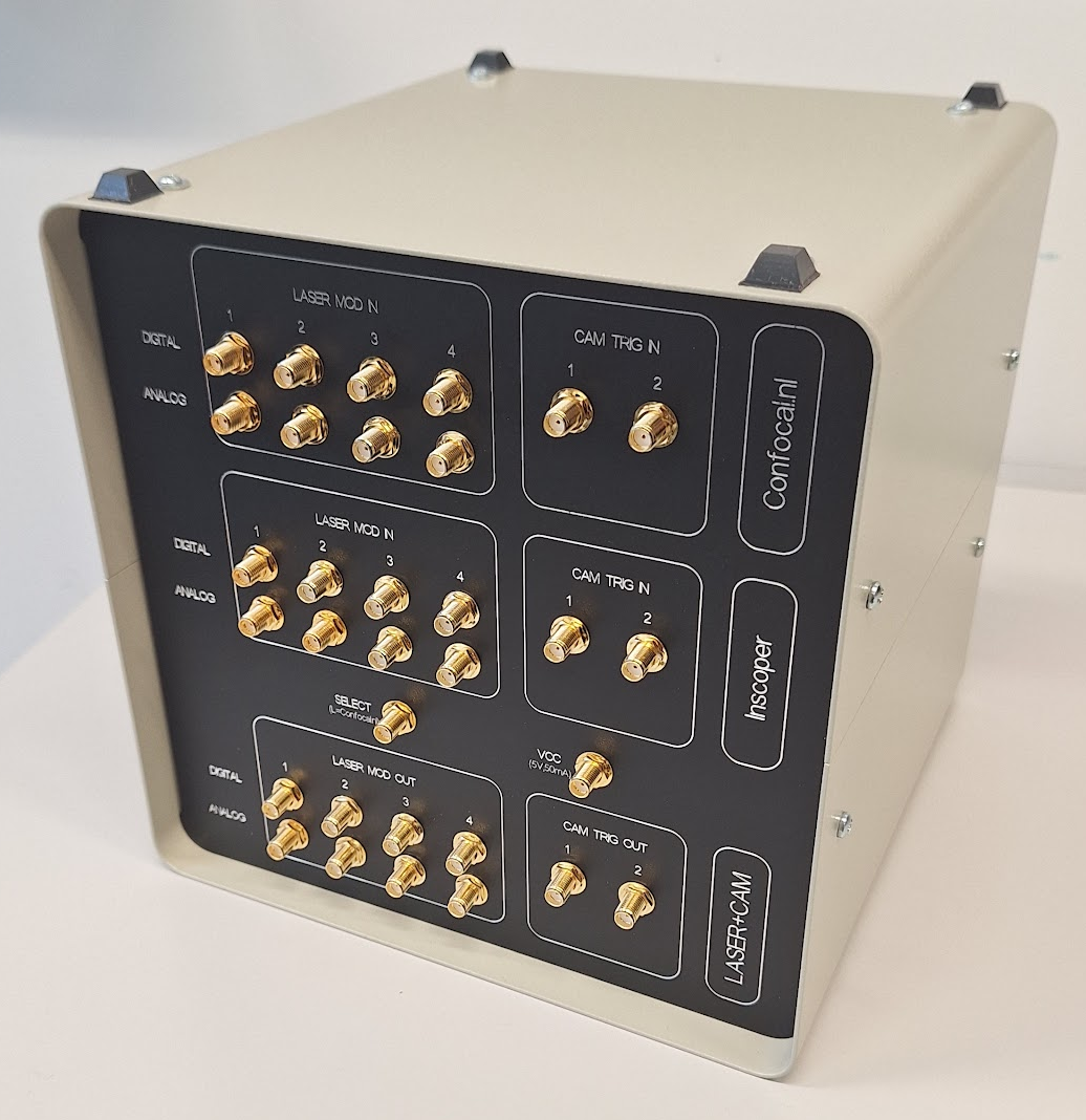
All the SELECT bits are common and a single SELECT signal is also taken from the Inscoper Device Controller. This signal effectively switches between AION control and Inscoper control (for the cameras and lasers).
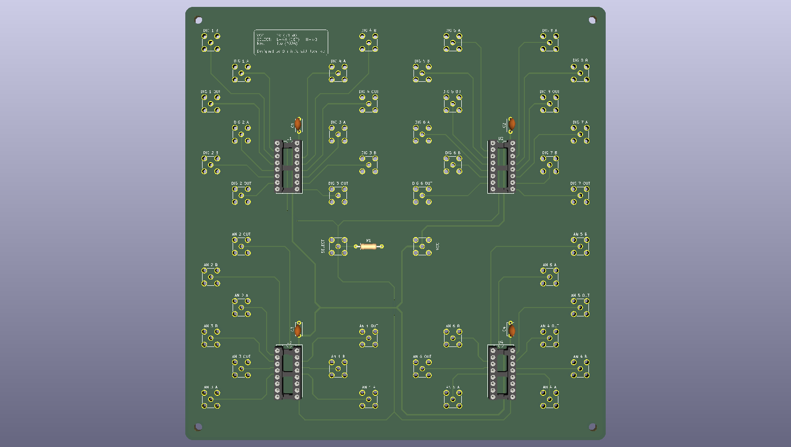
Dual ctrl an dig mux is an open-source printed circuit board by Omnistic, from the Omnistic/aion_bypass_pcb repository on GitHub, published under the MIT licence. It is a 2-layer board of 165 × 170 mm with 57 parts on 45 nets, routed with 242 tracks and 4 vias.
It is built around the 74HC157D and 74HC4053D. Its parts include 4 capacitors, 4 ICs and 1 resistor.

SELECT line, one can either use the AION (Confocal.nl) or a FRAP/TIRF module with the AION in bypass mode.HIGH.The AION microscope is controlled by Confocal.nl's own controller. The Confocal.nl controller can also be controlled by the Inscoper Device Controller. The Inscoper Device Controller can control other devices as well. For this reason, the AION can be set into an optical bypass mode, which allows accessing the cameras through the AION without making use of the ReScan, to instead perform other kinds of microscopy. However, the cameras and the laser lines (analog and digital) are normally wired to the Confocal.nl controller. This limits the way in which the cameras and the laser lines can be controlled at the level of the Inscoper Device Controller for use in other applications.
For two controllers to send signals to the same device, multiplexing is necessary. In the case of the camera trigger (digital) signal, it is not possible to simply use a T-connector because if one controller is high and the other is low a large short-circuit current would flow directly between the two controllers' outputs as they fight each other, potentially damaging the controllers, while the shared node would sit at an undefined voltage that the device could not reliably interpret as high or low.
⚠️ Those are for my particular case, please check the documentation of your devices accordingly.
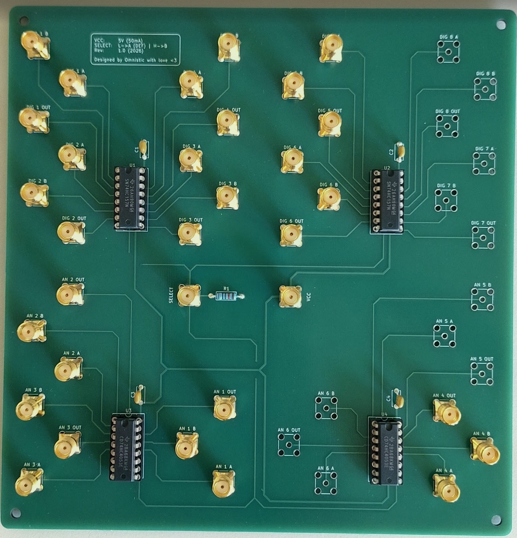
SN74HC157N is a 4 x 2:1 digital multiplexer, with a single SELECT bit. Two will be used for a total of 8 (2:1) digital channels. Although only 6 are required.
CD74HC4053E is 3 x 2:1 analog multiplexer, with three SELECT bits (1 per channel). Two will be used for a total of 6 (2:1) analog channels. Although only 4 are required.
Assuming up to two lasers are operated simultaneously, the current drawn from 2 digital and 2 analog lines is 40mA. On top of that, the two cameras only contribute 1mA (assuming 10kΩ). Multiplying by a safety factor of 1.2 that is about 50mA. The power will be supplied to the board via the Inscoper Device Controller directly.
All the SELECT bits are common and a single SELECT signal is also taken from the Inscoper Device Controller. This signal effectively switches between AION control and Inscoper control (for the cameras and lasers).
The SELECT line is pulled down by a 10kΩ resistor, defaulting to LOW, which corresponds to AION (for my use case).
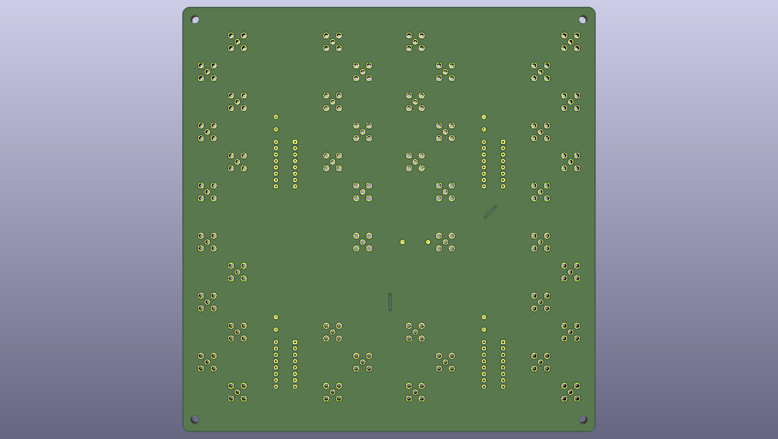
Only the SELECT crosses the PCB with minimal length in the back face to keep continuous ground zone.
100nF capacitors are used on each IC for decoupling.
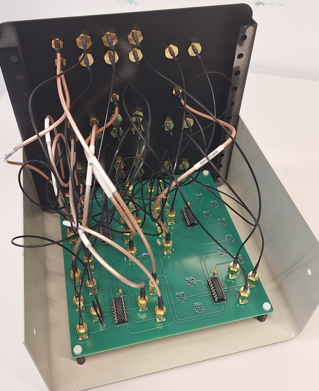
Vertical through-hole SMA connectors will be soldered to the PCB. The PCB will be mounted in a case and a front panel will have SMA (inside facing) to SMB (outside facing) connectors. Minimum distance between SMA connectors optimized for accessible mounting.
Note: I originally ordered SMA-Bulkhead cables that were thicker (not intentionally) but they sent only a few and the others were on back order. I cancelled the order and got those above that are thinner. The reason I say this is because it is easier to assemble with the thin cables imo. And also, I am sorry for the poor cable management... The enclosure foot print is perhaps a tiny bit too small but it works.
We thank Alfonso Fontao Blanco from the Microelectronics Design Center (ETHZ) for kindly reviewing the design and suggesting minor improvements (more distance between SMA connectors, mounting holes, shorter SELECT line on the back face).
| Qty | Value | Footprint | References |
|---|---|---|---|
| 44 | Conn_Coaxial | Connector_Coaxial:SMA_Amphenol_901-144_Vertical | AN 1 A, AN 1 B, AN 1 OUT, AN 2 A, AN 2 B, AN 2 OUT, AN 3 A, AN 3 B, AN 3 OUT, AN 4 A, AN 4 B, AN 4 OUT, AN 5 A, AN 5 B, AN 5 OUT, AN 6 A +28 |
| 4 | 100nF | Capacitor_THT:C_Disc_D5.0mm_W2.5mm_P5.00mm | C1, C2, C3, C4 |
| 2 | 74HC157 | Package_DIP:DIP-16_W7.62mm_Socket | U1, U2 |
| 2 | 74HC4053 | Package_DIP:DIP-16_W7.62mm_Socket | U3, U4 |
| 1 | 10k | Resistor_THT:R_Axial_DIN0207_L6.3mm_D2.5mm_P10.16mm_Horizontal | R1 |
The 53 most common of 57 parts.
cyberboy666/sync_ope
effect send + sync restoring circuit - adapted from a gael jaton design

brengi/CESE-PCB
Curso de Diseño de Circuitos Impresos de la Carrera de Especialización en Sistemas Embebidos


ModularMayhem/mmm
A eurorack filter created in collaboration by the modular mayhem DIY folks

cbaurtx/RetroBox
RetroBox is an internet radio using an ESP32-S3 system on a chip


It measures 165 × 170 mm and has 2 copper layers, 1.6 mm thick.
57 parts, built around the 74HC157D and 74HC4053D. The full list of its parts is on this page, with links to each part's symbol and footprint where PCBKit's library has them.
From the Omnistic/aion_bypass_pcb repository on GitHub, at the commit this page was made from: the board is dual_ctrl_an_dig_mux/dual_ctrl_an_dig_mux.kicad_pcb and its schematic dual_ctrl_an_dig_mux/dual_ctrl_an_dig_mux.kicad_sch. PCBKit opens the board in the browser, with nothing to install.
Its repository publishes it under the MIT licence: you may reuse it on that licence's terms (keep the author's notice, and for a copyleft licence share your changes alike).