2 layers98.6 × 83.3 mm
ThorDriveController ProtoV0
Omar-Magdy0/Proto_V0
The controller board enables BLDC motor control using ATmega328P and supports BEMF zero-crossing sensorless operation.
68 parts

 Omar-Magdy0/Proto_V0
The controller board enables BLDC motor control using ATmega328P and supports BEMF zero-crossing sensorless operation.
ThorDriveInverter ProtoV0 is an open-source printed circuit board by Omar-Magdy0, from the Omar-Magdy0/Proto_V0 repository on GitHub. It is a 2-layer board of 100 × 99.4 mm with 149 parts on 71 nets, routed with 349 tracks and 32 vias.
It is built around the ACS712ELCTR-30A-T-JSM, IR2130PBF and AMS1117-3.3, with the SD103AWS, IRF1407 and SS310 among its other parts. Its parts include 34 capacitors, 32 resistors, 19 diodes, 14 connectors and 6 transistors.


📁 Controller
v1.0ATmega328PKiCadThe controller board enables BLDC motor control using ATmega328P and supports BEMF zero-crossing sensorless operation.
Remove onBoard Potentiometer if going to install external Potentiometer
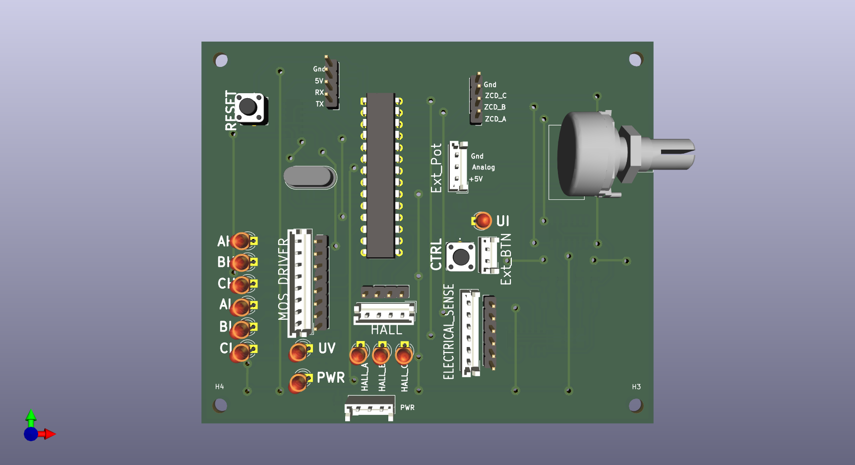
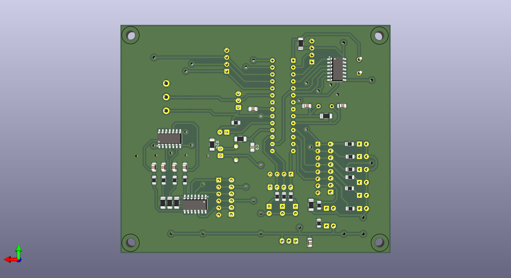
| Type | Path |
|---|---|
| 🧩 3D Model | ./Controller/Docs/*.step |
| 📝 Schematic | ./Controller/Docs/*.pdf |
| 📂 Design Files | ./Controller |
Try with: https://3dviewer.net/
Upload: ./Controller/Docs/*.step
📁 Inverter
v1.0KiCad2KW+IR2130Each phase is conditioned via:
$V_{cond} = V_{phase-ground} \times \left(\frac{2.2k}{49.2k}\right)$
Filtered with 80kHz low-pass
Calibrate as needed due to resistor tolerances
For Phase A & B:
$V_{cond} = \left( I_{line} \times 66\text{mV} + 2.5 \right) \times \left(\frac{5.1k}{15.1k}\right)$
Filtered with 80kHz low-pass
Calibrate as needed due to resistor tolerances
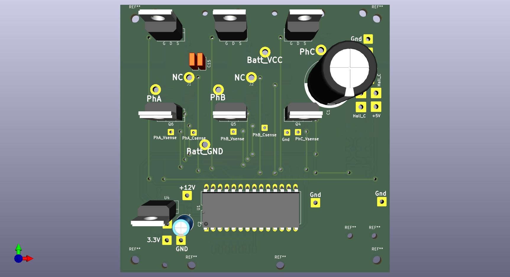
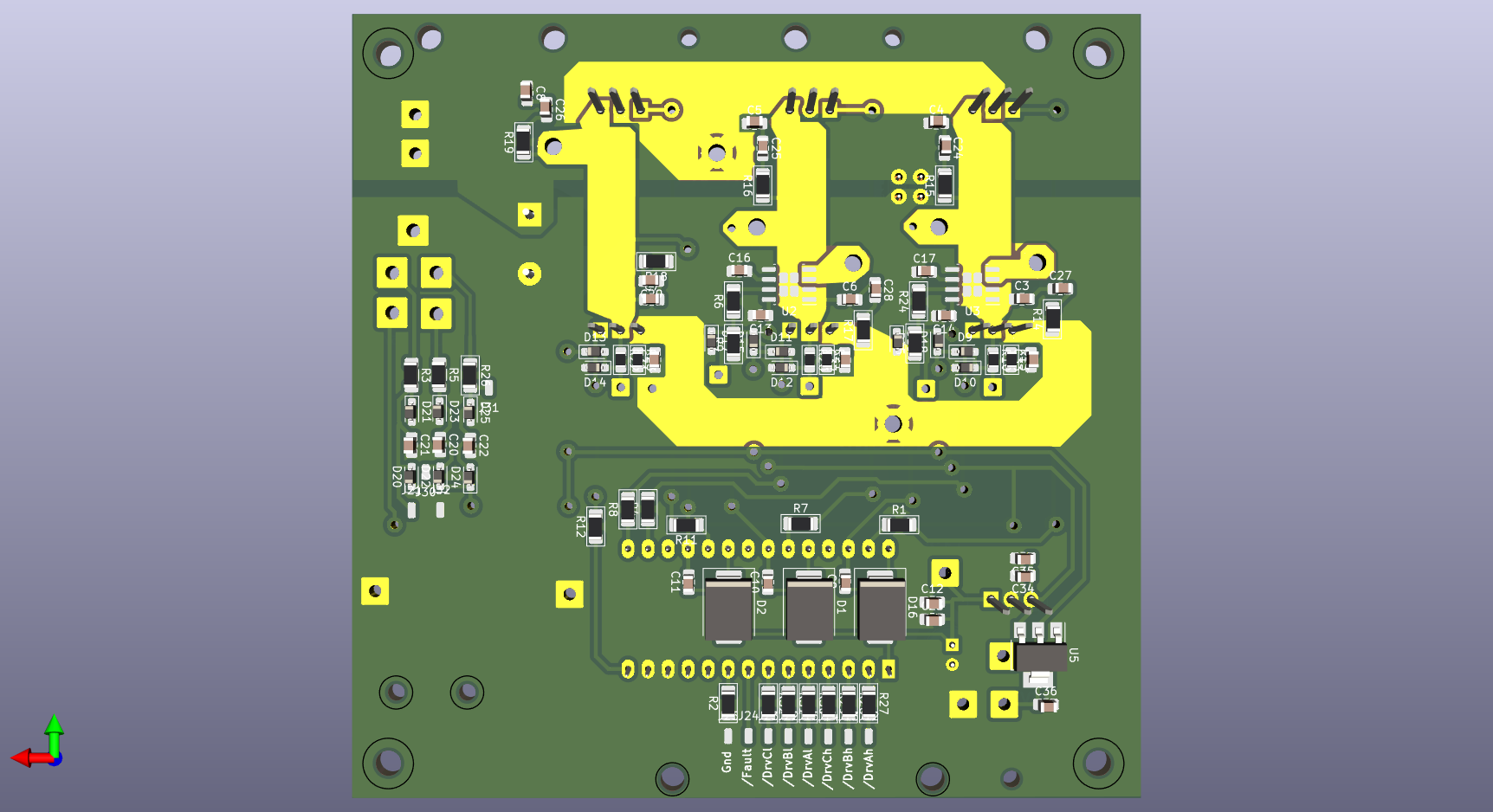
| Type | Path |
|---|---|
| 🧩 3D Model | ./Inverter/Docs/*.step |
| 📝 Schematic | ./Inverter/Docs/*.pdf |
| 📂 Design Files | ./Inverter |
Try with: https://3dviewer.net/
Upload: Docs/*.step
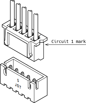
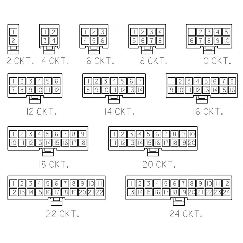
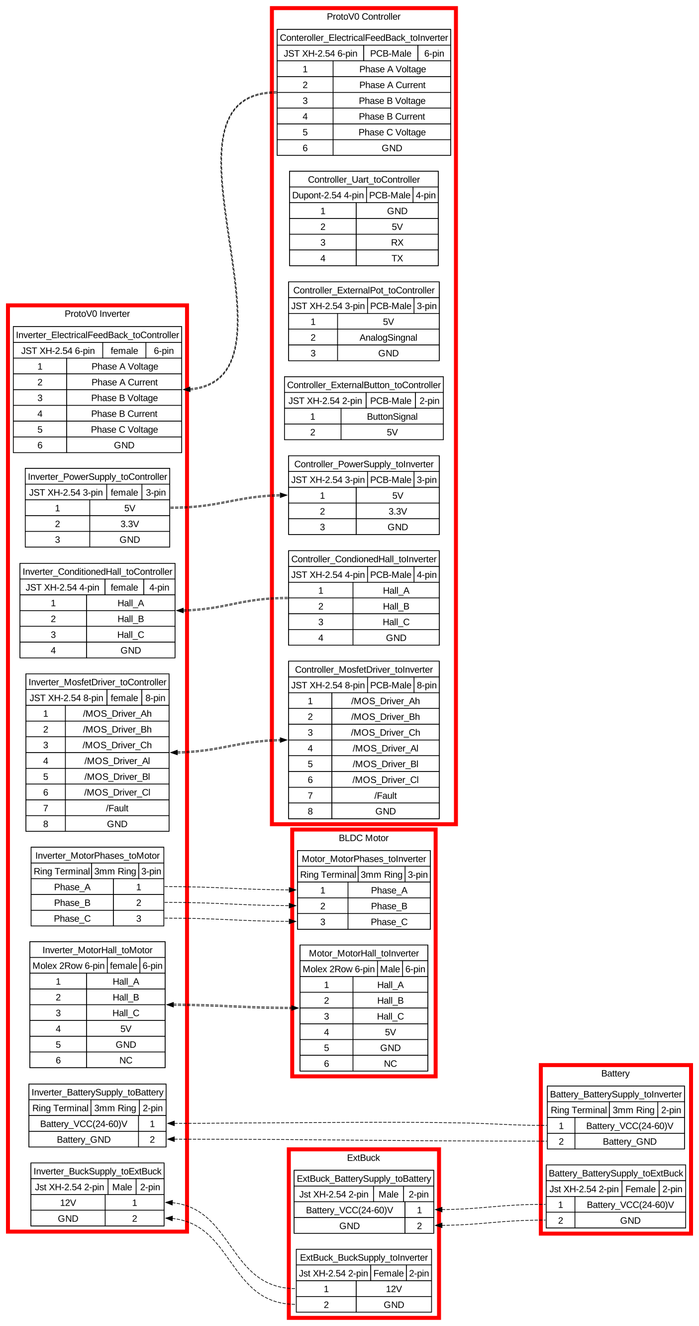
Proper connector pin labeling is essential for integration with other subsystems (sensors, MCU, battery, etc.). Images and pinout illustrations will help ensure correct assembly.
JST
Molex
🔌 Sample Harness:
Maintainer: Omar Magdy 📧 omar.magdy.om.om@gmail.com
| Qty | Value | Footprint | References |
|---|---|---|---|
| 16 | SD103AWS | Diode_SMD:D_SOD-323_HandSoldering | D9, D10, D11, D12, D13, D14, D15, D17, D18, D19, D20, D21, D22, D23, D24, D25 |
| 13 | , , , , , , , , , , , , | ||
| 12 | 4.7nF | Capacitor_SMD:C_0805_2012Metric_Pad1.18x1.45mm_HandSolder | C3, C4, C5, C6, C7, C8, C24, C25, C26, C27, C28, C29 |
| 12 | ~ | Connector_Wire:SolderWirePad_1x01_SMD_1x2mm | J12, J13, J14, J15, J21, J22, J23, J24, J25, J30, J31, J32 |
| 7 | 100 | PCM_Resistor_SMD_AKL:R_1206_3216Metric_Pad1.30x1.75mm_HandSolder | R14, R15, R16, R17, R18, R19, R26 |
| 7 | 2.2uF | Capacitor_SMD:C_0805_2012Metric_Pad1.18x1.45mm_HandSolder | C9, C10, C11, C12, C34, C35, C36 |
| 6 | 15 | PCM_Resistor_SMD_AKL:R_1206_3216Metric_Pad1.30x1.75mm_HandSolder | R1, R4, R7, R8, R11, R12 |
| 6 | 470 | PCM_Resistor_SMD_AKL:R_1206_3216Metric_Pad1.30x1.75mm_HandSolder | R27, R28, R29, R30, R31, R32 |
| 6 | IRF1407 | PCM_Package_TO_SOT_THT_AKL:TO-220-3_Vertical_GDS | Q1, Q2, Q3, Q4, Q5, Q6 |
| 5 | 1nF | Capacitor_SMD:C_0805_2012Metric_Pad1.18x1.45mm_HandSolder | C16, C17, C31, C32, C33 |
| 5 | ~ | Connector_Wire:SolderWire-1sqmm_1x01_D1.4mm_OD3.9mm | +5V, Hall_A, Hall_C, Hall_C, Hall_Gnd |
| 3 | 0.1uF | Capacitor_SMD:C_0805_2012Metric_Pad1.18x1.45mm_HandSolder | C13, C14, C23 |
| 3 | 10nF | Capacitor_SMD:C_0805_2012Metric_Pad1.18x1.45mm_HandSolder | C20, C21, C22 |
| 3 | 2.2k | PCM_Resistor_SMD_AKL:R_0805_2012Metric_Pad1.15x1.40mm_HandSolder | R13, R21, R23 |
| 3 | 47K | PCM_Resistor_SMD_AKL:R_0805_2012Metric_Pad1.15x1.40mm_HandSolder | R10, R20, R22 |
| 3 | SS310 | Diode_SMD:D_SMC | D1, D2, D16 |
| 2 | 100 | Resistor_SMD:R_1206_3216Metric_Pad1.30x1.75mm_HandSolder | R3, R5 |
| 2 | 10K | PCM_Resistor_SMD_AKL:R_1206_3216Metric_Pad1.30x1.75mm_HandSolder | R9, R25 |
| 2 | 2.2uF | Capacitor_THT:C_Rect_L4.6mm_W2.0mm_P2.50mm_MKS02_FKP02 | C15, C30 |
| 2 | 5K | PCM_Resistor_SMD_AKL:R_1206_3216Metric_Pad1.30x1.75mm_HandSolder | R6, R24 |
| 2 | ACS712ELCTR30AT | Package_SO:SOIC-8-1EP_3.9x4.9mm_P1.27mm_EP2.95x4.9mm_Mask2.71x3.4mm | U2, U3 |
| 1 | 10k | PCM_Resistor_SMD_AKL:R_1206_3216Metric_Pad1.30x1.75mm_HandSolder | R2 |
| 1 | 15 Gnd | Connector_Wire:SolderWire-0.75sqmm_1x01_D1.25mm_OD3.5mm | Gnd |
| 1 | 15Vin | Connector_Wire:SolderWire-0.75sqmm_1x01_D1.25mm_OD3.5mm | +12V |
| 1 | 22uF | Capacitor_THT:CP_Radial_D6.3mm_P2.50mm | C2 |
| 1 | 470uF | Capacitor_THT:CP_Radial_D18.0mm_P7.50mm | C1 |
| 1 | AMS1117-3.3 | Package_TO_SOT_SMD:SOT-223-3_TabPin2 | U5 |
| 1 | Bat Gnd | libMain:12AWG cableSoldered | Batt_GND |
| 1 | Bat VCC | libMain:12AWG cableSoldered | Batt_VCC |
| 1 | GND0_sense | Connector_Wire:SolderWire-0.5sqmm_1x01_D0.9mm_OD2.3mm | Gnd |
| 1 | IR2130PBF | PCM_Package_DIP_AKL:DIP-28_W15.24mm_LongPads | U1 |
| 1 | LM7805_TO220 | Package_TO_SOT_THT:TO-220-3_Vertical | U4 |
| 1 | Motor_phaseA | libMain:10mm2 CableSoldered | J1 |
| 1 | Motor_phaseASensed | libMain:10mm2 CableSoldered | PhA |
| 1 | Motor_phaseB | libMain:10mm2 CableSoldered | J2 |
| 1 | Motor_phaseBSensed | libMain:10mm2 CableSoldered | PhB |
| 1 | Motor_phaseC | libMain:10mm2 CableSoldered | PhC |
| 1 | PhaseA_Csense | Connector_Wire:SolderWire-0.5sqmm_1x01_D0.9mm_OD2.3mm | PhA_Csense |
| 1 | PhaseA_Vsense | Connector_Wire:SolderWire-0.5sqmm_1x01_D0.9mm_OD2.3mm | PhA_Vsense |
| 1 | PhaseB_Csense | Connector_Wire:SolderWire-0.5sqmm_1x01_D0.9mm_OD2.3mm | PhB_Csense |
| 1 | PhaseB_Vsense | Connector_Wire:SolderWire-0.5sqmm_1x01_D0.9mm_OD2.3mm | PhB_Vsense |
| 1 | PhaseC_Vsense | Connector_Wire:SolderWire-0.5sqmm_1x01_D0.9mm_OD2.3mm | PhC_Vsense |
The 141 most common of 149 parts.
Omar-Magdy0/Proto_V0
The controller board enables BLDC motor control using ATmega328P and supports BEMF zero-crossing sensorless operation.


Omar-Magdy0/ForgeDriveHW
ForgeDrive is an open-source research and development platform for modular, scalable, and industrial-inspired systems.


It measures 100 × 99.4 mm and has 2 copper layers, 1.6 mm thick.
149 parts, built around the ACS712ELCTR-30A-T-JSM, IR2130PBF, AMS1117-3.3 and SD103AWS. The full list of its parts is on this page, with links to each part's symbol and footprint where PCBKit's library has them.
From the Omar-Magdy0/Proto_V0 repository on GitHub, at the commit this page was made from: the board is Inverter/ThorDriveInverter_ProtoV0.kicad_pcb and its schematic Controller/Signal Conditioning.kicad_sch. PCBKit opens the board in the browser, with nothing to install.
Its repository states no licence, so its author keeps all rights: ask Omar-Magdy0 before reusing the design.