

2 layers150 × 100 mm

 NotoFederico/FuncGen1
A WiFi function and arbitrary wave generator
Amplificador is an open-source printed circuit board by NotoFederico, from the NotoFederico/FuncGen repository on GitHub, published under the GPL-3.0 licence. It is a 2-layer board of 150 × 100 mm with 46 parts on 44 nets, routed with 456 tracks and 28 vias.
It is built around the TL072 and CD4051BE. Its parts include 27 resistors, 5 ICs, 4 diodes, 4 connectors and 3 capacitors. It belongs with the radio and wireless boards of this library.
| Latest release | Latest development build |
|---|---|
 |  |
The present project aims to develop a function generator, which is exactly what its name implies: a test equipment that generates electrical signals in the form of waves that are used as stimuli for electronic measurements.
Most circuits require some type of input signal whose amplitude varies with time. The signal can be an alternating current signal (with peaks that oscillate above and below a reference) or it can vary over a range of direct current offset voltages, either positive or negative. It can be a sine wave or other analog function, a digital pulse, a binary pattern, or a purely arbitrary waveform.
The generator of signals, or functions, is the source of stimulus. Pair with a data acquisition instrument for a complete measurement solution. The two tools are connected to the input and output terminals of the device under test (DUT).
The signal generator can provide "ideal" waveforms, or it can add known and repeatable amounts and types of distortion (or errors) to the signal it delivers. This feature is one of the greatest virtues of the signal generator, as it is often impossible to create predictable distortion, exactly when and where it is needed, using only the circuit itself. The response of the device under test (DUT) in the presence of these distorted signals reveals its ability to handle voltages that fall outside the envelope of normal performance.
There are hundreds of different applications for this class of equipment, but placed in a context of electronic measurements, three categories can be divided: Verification: the designers of wireless equipment that develop new transmitting and receiving hardware must simulate baseband I&Q signals, with and without deficiencies, to verify compliance with proprietary wireless standards using arbitrary low-distortion functions.
Characterization: Newly developed digital-to-analog converters (DACs) and analog-to-digital converters (ADCs) must be thoroughly tested for their limits for linearity and distortion. Analog and digital signals are applied in phase to bring the speeds of these devices up to 1Gbps. Stress or margin test: engineers working with serial data flow architectures (commonly used in digital communication buses) need to stress their devices with deficiencies, particularly fluctuations and synchronization violations
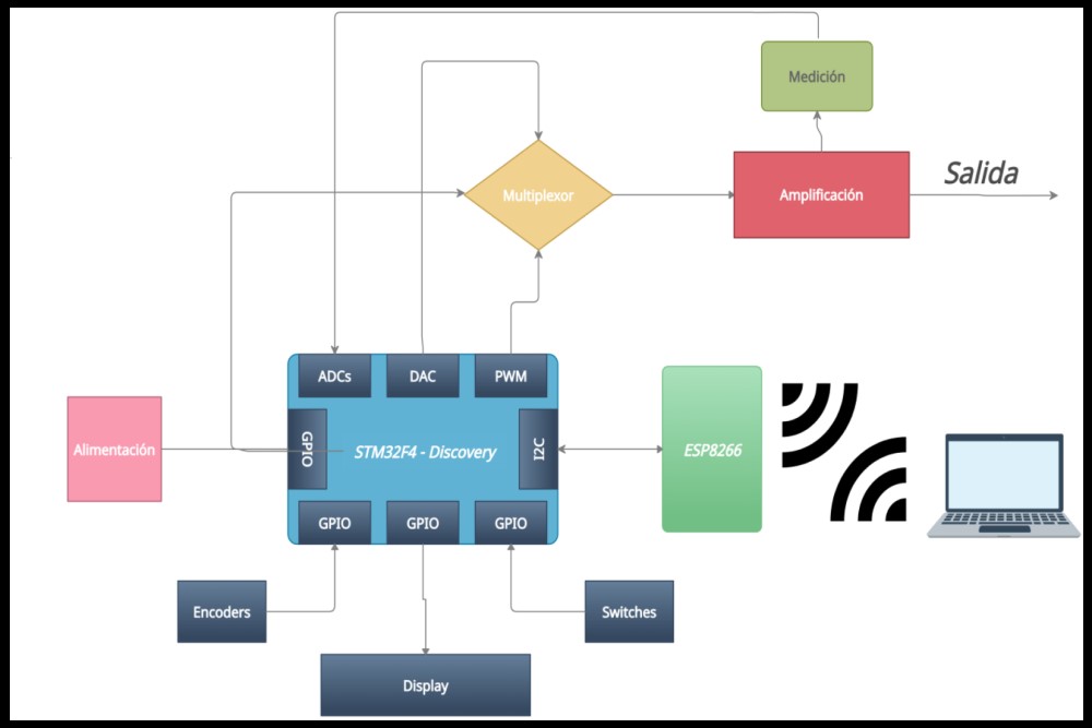
In the project in question, known signals can be generated: such as sine, semi-diverse, square, rectangular, triangular, sawtooth and white noise and arbitrary signals, which are those signals of complex origin that do not follow a regular mathematical expression and that can be generated by the user using specialized software and subsequently sent over WiFi, thanks to a dedicated website. These signals can be chosen through a menu and their parameters, such as duty, offset and amplitude, are modifiable and will be monitored in real time on a display.
FuncGen uses the gitflow workflow. If you are implementing a new feature or logic from the original game, please branch off and perform pull requests to develop. If you are fixing a bug for the next release, please branch off and perform pull requests to the correct release branch. master only contains tagged releases, you should never branch off this.
FuncGen is licensed under the GNU General Public License version 3.
| Qty | Value | Footprint | References |
|---|---|---|---|
| 15 | 10k | Resistor_THT:R_Axial_DIN0207_L6.3mm_D2.5mm_P10.16mm_Horizontal | R5, R6, R8, R9, R11, R12, R13, R17, R18, R20, R21, R22, R24, R26, R27 |
| 4 | TL072 | Package_DIP:DIP-8_W7.62mm_LongPads | U1, U2, U4, U5 |
| 3 | 33k | Resistor_THT:R_Axial_DIN0207_L6.3mm_D2.5mm_P10.16mm_Horizontal | R10, R14, R15 |
| 2 | 100nF | Capacitor_THT:C_Rect_L9.0mm_W2.5mm_P7.50mm_MKT | C2, C3 |
| 2 | 1N4007 | Diode_THT:D_DO-41_SOD81_P10.16mm_Horizontal | D3, D4 |
| 2 | 2.7k | Resistor_THT:R_Axial_DIN0207_L6.3mm_D2.5mm_P10.16mm_Horizontal | R19, R25 |
| 2 | 3.3k | Resistor_THT:R_Axial_DIN0207_L6.3mm_D2.5mm_P10.16mm_Horizontal | R16, R23 |
| 2 | 47k | Resistor_THT:R_Axial_DIN0207_L6.3mm_D2.5mm_P10.16mm_Horizontal | R2, R4 |
| 2 | 8.2k | Resistor_THT:R_Axial_DIN0207_L6.3mm_D2.5mm_P10.16mm_Horizontal | R1, R3 |
| 2 | Conn_01x03_Male | Connector_PinSocket_2.54mm:PinSocket_1x03_P2.54mm_Vertical | J2, J3 |
| 2 | D_Zener | Diode_THT:D_DO-15_P10.16mm_Horizontal | D1, D2 |
| 1 | 100k | Potentiometer_THT:Potentiometer_Alps_RK163_Dual_Horizontal | RV2 |
| 1 | 100n | Capacitor_THT:C_Rect_L9.0mm_W2.5mm_P7.50mm_MKT | C1 |
| 1 | 10k | Potentiometer_THT:Potentiometer_Alps_RK163_Single_Horizontal | RV1 |
| 1 | 5.6k | Resistor_THT:R_Axial_DIN0207_L6.3mm_D2.5mm_P10.16mm_Horizontal | R7 |
| 1 | BF245B | Package_TO_SOT_THT:TO-92L_Inline_Wide | Q1 |
| 1 | CD4051B | Package_DIP:DIP-16_W7.62mm_LongPads | U3 |
| 1 | Conn_01x02_Male | Connector_PinSocket_2.54mm:PinSocket_1x02_P2.54mm_Vertical | J4 |
| 1 | Screw_Terminal_01x05 | TerminalBlock_Altech:Altech_AK300_1x05_P5.00mm_45-Degree | J1 |

polykit/polykit-x-voice-card
Schematics and PCB layout for a voice card with multimode filter for a polyphonic synthesizer

polykit/polykit-x-mainboard
Schematics and PCB layout for a mainboard for an 8 voice polyphonic synthesizer


cpldcpu/TouchSynth
Analog Monophonic Synthesizer with a touch keyboard. Controller by CH32V00x


james-l-key/Esp32_patch_bay_circuit
Circuit and PCB for Esp32_patch_bay


SamyIOoOI/RetroCom
A 4-Station one-to-one two-way INTERCOM built around the AT89C52-PI24 RetroMCU (8051 Core).
It measures 150 × 100 mm and has 2 copper layers, 1.6 mm thick.
46 parts, built around the TL072 and CD4051BE. The full list of its parts is on this page, with links to each part's symbol and footprint where PCBKit's library has them.
From the NotoFederico/FuncGen repository on GitHub, at the commit this page was made from: the board is FuncGen_Amplifier/FuncGen[Amplifier v.1.2]/Amplificador.kicad_pcb. PCBKit opens the board in the browser, with nothing to install.
Its repository publishes it under the GPL-3.0 licence: you may reuse it on that licence's terms (keep the author's notice, and for a copyleft licence share your changes alike).