


4 layers15 × 29.2 mm
Fuimini V2
Zipra1/Fuimini-V2
nRF flavoured SlimeVR-compatible trackers. Now with higher volume production in mind!
62 parts3CERN-OHL-S-2.0

 NicholasKorth/Slim-Sleep-Tracker
A low-profile wrist wearable that measures motion, optical heart rate and SpO2 and streams them over Bluetooth LE to a PC visualizer.
Tracker PCB is an open-source printed circuit board by NicholasKorth, from the NicholasKorth/Slim-Sleep-Tracker repository on GitHub. It is a 4-layer board of 31.8 × 15.3 mm with 64 parts on 94 nets, routed with 520 tracks and 234 vias.
It is built around the NRF52840-QIAA-R, MAX30208CLB+T and MAXM86161EFD+T, with the BQ25120AYFPR, GT-USB-7010ASV and LSM6DSV16XTR among its other parts. Its parts include 30 capacitors, 11 resistors, 7 ICs, 3 inductors and 2 switches. It belongs with the nRF52 and nRF5x boards of this library.


A low-profile wrist wearable that measures motion, optical heart rate and SpO2 and streams them over Bluetooth LE to a PC visualizer.
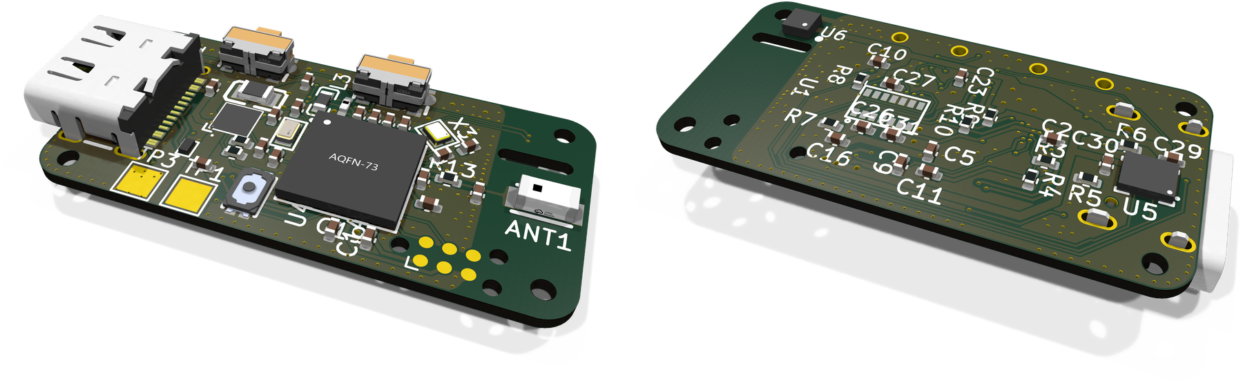
3D renders from the board file: top side on the left, bottom (skin) side on the right. The optical sensor U1 has no 3D model and shows as bare pads.
The tracker is a 31.75 x 15.25 mm board worn on the inner wrist. The motion sensor, the optical heart-rate and SpO2 sensor and the skin temperature sensor sit on the bottom side, against the skin. The top side carries the nRF52840 microcontroller and radio, the USB-C charging port, the charger, two side buttons and a chip antenna. The firmware streams sensor packets over Bluetooth LE, and a Python visualizer on a PC shows orientation, the optical (PPG) signal, heart rate, SpO2 and battery level.
It is part of a sleep project and pairs with my Dual-Zone Bed Climate System, BedCooler. The link between the two is not part of this firmware.
This is not a medical device. The heart-rate and SpO2 values are experimental and have not been validated against a reference.
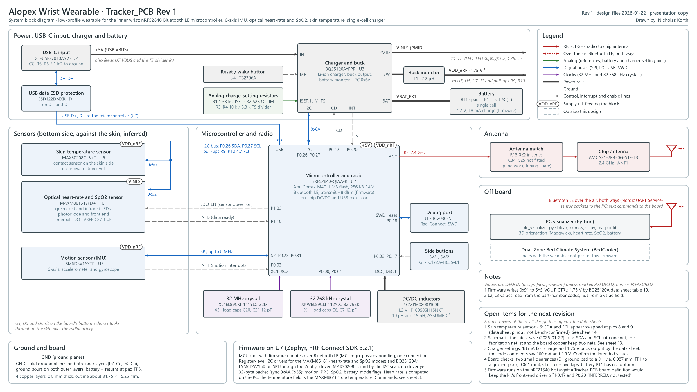
Block diagram as SVG. More views: one-page overview, angled render, top render, bottom render, signal map, functional layout, and the full schematic as PDF.
Values come from the design files (schematic, board and firmware), not from measurements.
| Microcontroller and radio | Nordic nRF52840 (Cortex-M4F, 1 MB flash, 256 KB RAM), Bluetooth LE at +8 dBm, chip antenna |
| Motion | ST LSM6DSV16X accelerometer and gyroscope on SPI (up to 8 MHz) |
| Optical | Maxim MAXM86161 heart-rate and SpO2 module on I2C (green LED for heart rate, red and infrared for SpO2) |
| Skin temperature | Maxim MAX30208 on I2C (fitted, no firmware driver yet) |
| Power | USB-C 5 V input; TI BQ25120A charger with buck output; single-cell lithium battery (off the board) |
| Board | 31.75 x 15.25 mm, 0.8 mm thick, 4 copper layers (both inner layers ground); 60 parts on both sides |
| Firmware | Zephyr on nRF Connect SDK 3.2.1, MCUboot bootloader, firmware updates over Bluetooth |
| Data link | Nordic UART Service; 32-byte sensor packets at about 12.5 per second; text commands |
hardware/          KiCad 9 project: schematic (4 sheets), routed board, project-local
                   symbol/footprint/3D-model library (libs/), board STEP model
hardware/production/  Gerbers and drill files (Tracker_PCB.zip), IPC netlist, BOM, placement
firmware/          Zephyr application for the nRF52840 (see firmware/README.md)
firmware/prototype/   earlier bring-up firmware and test scripts, kept for reference
tools/visualizer/  Python Bluetooth LE visualizer
docs/ schematic PDF, block diagram, firmware diagram and board rendersOpen hardware/Tracker_PCB.kicad_pro in KiCad 9. The parts library is inside the project (hardware/libs/easyeda2kicad), so no global library setup is needed. The 0402 resistors and capacitors use KiCad's own 3D models.
| Sheet | Contents |
|---|---|
Tracker_PCB.kicad_sch | Root: system overview and the connections between sheets |
power.kicad_sch | USB-C input with ESD protection, BQ25120A charger and buck, battery, reset/wake button |
mcu.kicad_sch | nRF52840, 32 MHz and 32.768 kHz crystals, DC/DC inductors, antenna match, side buttons, Tag-Connect debug port, I2C pull-ups |
sensors.kicad_sch | MAXM86161 optical sensor, MAX30208 skin temperature sensor, LSM6DSV16X motion sensor |
The schematic here is a redrawn copy of my original five-sheet design with the same parts, values, footprints and connections. SDA and SCL are drawn as two separate nets, as on the fabricated board; my last save of the original schematic had joined them into one net by mistake.
The board file was routed against that original schematic. Its copper matches the Gerbers, but SDA and SCL still carry one shared net name there (/MCU NRF52840/P0.26), and its footprints point at the original sheets. Before editing the board, run Tools > Update PCB from Schematic with "Re-link footprints to schematic symbols based on their reference designators" turned on.
Bus and pin assignments:
The Gerbers in hardware/production/Tracker_PCB.zip (2025-12-26) are the set the board was ordered from, and their copper matches the board file. bom.csv and positions.csv are in the JLCPCB format from the KiCad fabrication toolkit. The battery BT1 is a schematic symbol only and has no footprint.
firmware/ is a Zephyr application that started from Nordic's Peripheral UART sample. Build and flash steps are in firmware/README.md.
nrf.START, STOP, STATUS, HR_ON, HR_OFF, SPO2_ON, SPO2_OFF, TEMP, HELP, and the experimental IMU_MODE / HEALTH_MODE pair (a 100 Hz motion-only packet).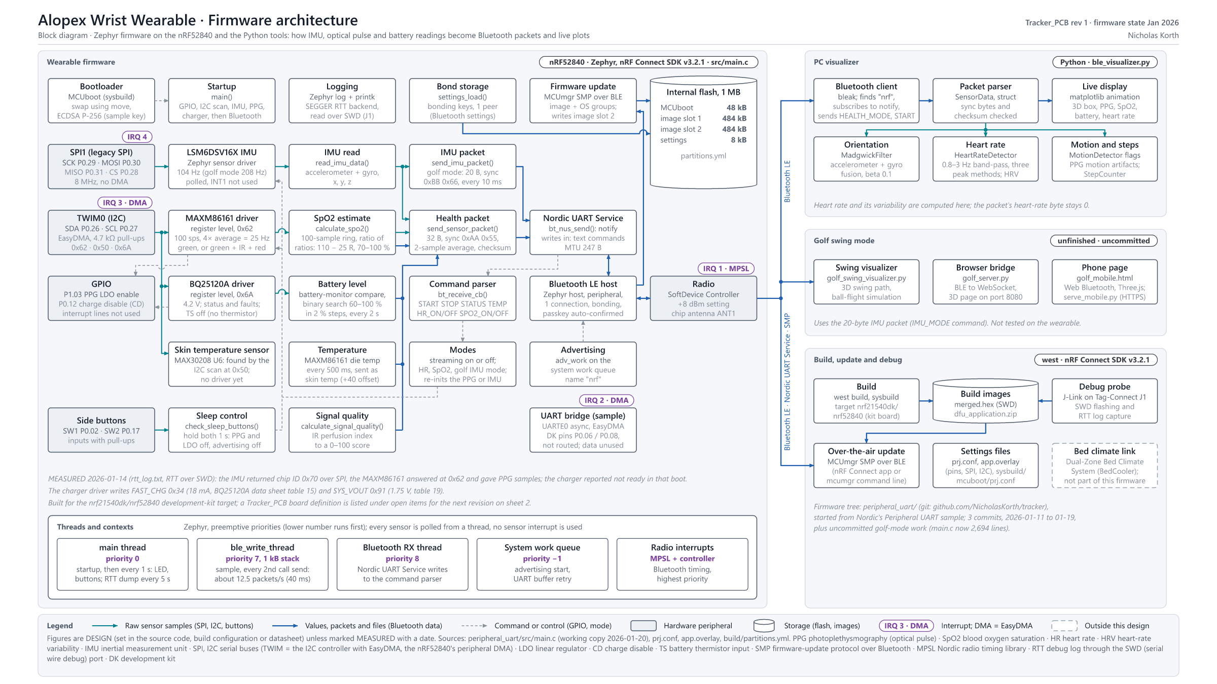
The firmware diagram also shows the golf-swing tools I used with IMU_MODE; they are experimental and not included in this repository.
tools/visualizer/ble_visualizer.py connects to the tracker, sends HEALTH_MODE and START, and plots live data: 3D orientation (Madgwick filter), the PPG signal with heart-rate detection, SpO2 and battery level. On-screen buttons switch the heart-rate and SpO2 modes.
cd tools/visualizer
python -m venv .venv
.venv\Scripts\activate          (Linux or macOS: source .venv/bin/activate)
pip install -r requirements.txt
python ble_visualizer.py
It needs Python 3.9 or later and a Bluetooth LE adapter on the PC, and it looks for a device whose name contains nrf. ble_scan.py lists nearby Bluetooth LE devices if the tracker is not found.
This is the first board revision and the project is partly unfinished. The firmware reads the motion sensor's ID over SPI and finds the optical sensor on I2C. The skin temperature sensor is fitted but not yet supported in firmware; the temperature field in the packet is currently the optical module's die temperature. There is no battery-life, current or accuracy measurement yet.
From a review of the rev 1 design files against the data sheets:
CC BY-NC-SA 4.0: Creative Commons Attribution-NonCommercial-ShareAlike 4.0 International. You may share and adapt this work for non-commercial purposes with attribution, under the same license. Firmware files that carry a Nordic Semiconductor copyright header (they started from Nordic's sample code) keep Nordic's 5-Clause license.
| Qty | Value | Footprint | References |
|---|---|---|---|
| 5 | 100nF | Capacitor_SMD:C_0402_1005Metric | C8, C14, C15, C16, C19 |
| 4 | 10uF | Capacitor_SMD:C_0402_1005Metric | C2, C3, C28, C31 |
| 4 | 12pF | Capacitor_SMD:C_0402_1005Metric | C6, C7, C20, C21 |
| 3 | 1uF | Capacitor_SMD:C_0402_1005Metric | C1, C26, C27 |
| 3 | 4.7µF | Capacitor_SMD:C_0402_1005Metric | C5, C9, C11 |
| 3 | N.C. | Capacitor_SMD:C_0402_1005Metric | C23, C25, C34 |
| 2 | .1uF | Capacitor_SMD:C_0402_1005Metric | C29, C30 |
| 2 | 1.0µF | Capacitor_SMD:C_0402_1005Metric | C10, C12 |
| 2 | 100k | Resistor_SMD:R_0402_1005Metric | R7, R8 |
| 2 | 4.7k | Resistor_SMD:R_0402_1005Metric | R9, R10 |
| 2 | 5.1k | Resistor_SMD:R_0402_1005Metric | R5, R6 |
| 2 | GT-TC172A-H035-L1 | easyeda2kicad:SW-SMD_GT-TC172A-H035-L1 | SW1, SW2 |
| 2 | TestPoint | TestPoint:TestPoint_Pad_2.0x2.0mm | TP1, TP3 |
| 1 | |||
| 1 | 0 | Resistor_SMD:R_0402_1005Metric | R13 |
| 1 | 1.33k | Resistor_SMD:R_0402_1005Metric | R1 |
| 1 | 100pF | Capacitor_SMD:C_0402_1005Metric | C22 |
| 1 | 10k | Resistor_SMD:R_0402_1005Metric | R3 |
| 1 | 3.3k | Resistor_SMD:R_0402_1005Metric | R4 |
| 1 | 4.7uF | Capacitor_SMD:C_0402_1005Metric | C4 |
| 1 | 47nF | Capacitor_SMD:C_0402_1005Metric | C13 |
| 1 | 523 | Resistor_SMD:R_0402_1005Metric | R2 |
| 1 | 820pF | Capacitor_SMD:C_0402_1005Metric | C18 |
| 1 | AMCA31-2R450G-S1F-T3 | easyeda2kicad:ANT-SMD_L3.2-W1.6_AMCA31 | ANT1 |
| 1 | BQ25120AYFPR | easyeda2kicad:DSBGA-25_L2.5-W2.6-R5-C5-P0.40-BL | U3 |
| 1 | CMI160808J100KT | easyeda2kicad:L0603 | L2 |
| 1 | Conn_ARM_SWD_TagConnect_TC2030-NL | Connector:Tag-Connect_TC2030-IDC-NL_2x03_P1.27mm_Vertical | J1 |
| 1 | ESD122DMXR | easyeda2kicad:X2SON-3_L1.0-W0.6-L | D1 |
| 1 | GT-USB-7010ASV | easyeda2kicad:USB-C-SMD_G-SWITCH_GT-USB-7010ASV | U2 |
| 1 | LSM6DSV16XTR | easyeda2kicad:LGA-14_L3.0-W2.5-P0.50-BR | U5 |
| 1 | MAX30208CLB+T | easyeda2kicad:LGA-10_L2.0-W2.0_MAX30208CLB | U6 |
| 1 | MAXM86161EFD+T | easyeda2kicad:OLGA-14_L4.3-W2.9-P0.60-TL | U1 |
| 1 | MLP2012S2R2MT0S1 | easyeda2kicad:L0805 | L1 |
| 1 | NRF52840-QIAA-R | easyeda2kicad:AQFN-73_L7.0-W7.0-P0.50-BL-EP4.8 | U7 |
| 1 | TS2306A 240GF MSM 9_C2976675 | easyeda2kicad:SW-SMD_4P-L3.0-W2.0-P0.85-LS3.5 | U4 |
| 1 | VHF100505H15NKT | easyeda2kicad:L0402-RD | L3 |
| 1 | XKWEL89CLI-112YLC-32.768K | easyeda2kicad:OSC-SMD_2P-L1.6-W1.0 | X1 |
| 1 | XL4EL89CKI-111YLC-32M | easyeda2kicad:CRYSTAL-SMD_4P-L1.6-W1.2-BL | X3 |
The 61 most common of 64 parts.
Zipra1/Fuimini-V2
nRF flavoured SlimeVR-compatible trackers. Now with higher volume production in mind!

JaphD/Phasetag
Compact nRF54L15 Bluetooth Channel Sounding tag with dual PCB antennas, motion sensing, and rechargeable power management. Designed in KiCad 10.

Protocentral/healthypi-move-hw
Hardware files for the HealthyPi Move


GiovaSanta/PulseOxyemeter-LotiBloxy
a bluetooth pulse oxymeter Printed Circuit Board Design Project. PCB is meant to take spo2 measurements and sends results to an application via Bluetooth


tracelabs-pcb/pocketssd-21
Compact USB 3.2 Gen2 to NVMe M.2 bridge PCB — JMS583, 6-layer

It measures 31.8 × 15.3 mm and has 4 copper layers, 0.8 mm thick.
64 parts, built around the NRF52840-QIAA-R, MAX30208CLB+T, MAXM86161EFD+T and BQ25120AYFPR. The full list of its parts is on this page, with links to each part's symbol and footprint where PCBKit's library has them.
From the NicholasKorth/Slim-Sleep-Tracker repository on GitHub, at the commit this page was made from: the board is hardware/Tracker_PCB.kicad_pcb and its schematic hardware/Tracker_PCB.kicad_sch. PCBKit opens the board in the browser, with nothing to install.
Its repository states no licence, so its author keeps all rights: ask NicholasKorth before reusing the design.