2 layers182 × 105 mm
PocketComputerUniversalInterface
N1UGK/PCUI_Public
Collection of Programs and Utilities for the Pocket Computer Universal Interface
161 parts15

 N1UGK/RetroLink_Public
RetroLink connects a standard POTS (Plain Old Telephone Service) analog telephone to the Internet over Wi-Fi, allowing peer-to-peer calling between devices and retro telephony interfacing.
RetroLink is an open-source printed circuit board by N1UGK, from the N1UGK/RetroLink_Public repository on GitHub. It is a 2-layer board of 154 × 91 mm with 95 parts on 123 nets, routed with 1,056 tracks and 141 vias.
It is built around the TLV320AIC1110PBS, PJS008-2120-0 and BQ24090DGQR, with the MAX40200AUK+T, HSMM-A100-S00J1 and TS02-66-55-BK-160-LCR-D among its other parts. Its parts include 30 resistors, 21 capacitors, 13 connectors, 11 ICs and 5 switches.


RetroLink connects a standard POTS (Plain Old Telephone Service) analog telephone to the Internet over Wi-Fi, allowing peer-to-peer calling between devices and retro telephony interfacing. The RetroLink is intended for private telephone networks in the same building, campus, or even across the globe. It will not require subscription fees or a third party "app" or platform to use. The idea came from my daughter (who is 6) asking for a phone to call her friends. This device can be configured for connecting a close circle of friends or family and using their chosen "phone number" to dial and connect to them. Any standard "retro" telephone can be plugged into the RetroLink.
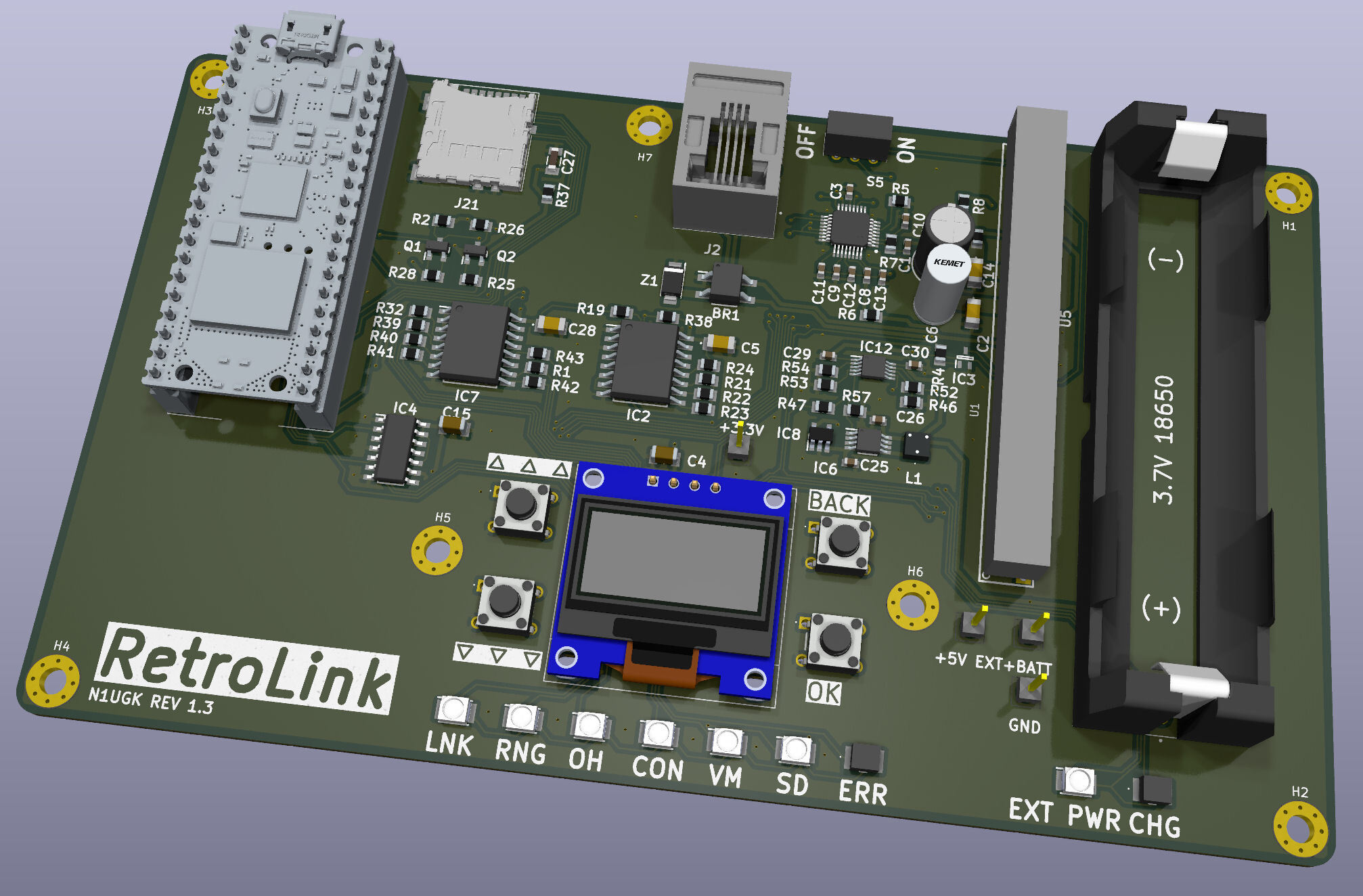
RetroLink provides a complete, self-contained telephone line interface for real analog telephones (both rotary and DTMF touch-tone). It generates real ringing voltages, provides line battery feed, detects off-hook and on-hook states, digitizes 2-wire voice audio with hardware codecs, and streams bidirectional voice data over Wi-Fi.
| Component | Specification |
|---|---|
| Microcontroller | Raspberry Pi Pico 2 W (RP2350 @ 150MHz) |
| SLIC Module | Silvertel Ag1170-S5 (5V, 600Ω 2-wire impedance) |
| Ring Generator | Onboard Ag1170 ringing (65Vrms @ 20Hz, REN 3 capable) |
| Voice Codec | TI TLV320AIC1110 (PCM / G.711 µ-law, 8 kHz) |
| Display | 0.96" 128x64 I2C OLED (0x3C) |
| I/O Expanders | 2x MAX7329 I2C Expanders (0x38, 0x3A) |
| Power Supply | Single 18650 Li-Ion Cell with BQ24090 Charger & MCP1642B 5V Boost |
| Connector | Standard RJ-11 6P4C Modular Phone Jack |
To update the firmware:
Settings -> Update Firmware, or hold the bootsel/startup button combo on power-up.RETROLINK will appear..uf2 file from the Firmware/ folder onto the drive.Firmware/: Official firmware release binaries (.uf2) and release notes.Hardware/: 3D CAD STEP models, schematics, and mechanical design files.Documentation/: User guides, application notes, and reference manuals.b99fa2f (Initial commit for RetroLink_Public repository structure)
| Qty | Value | Footprint | References |
|---|---|---|---|
| 13 | 10K | footprints:RESC2013X65N | R2, R4, R19, R21, R22, R23, R24, R25, R26, R28, R37, R46, R57 |
| 8 | 100nF | footprints:CAPC1608X90N | C1, C3, C8, C9, C10, C11, C12, C13 |
| 7 | 3.3K | footprints:RESC2013X65N | R1, R32, R39, R40, R41, R42, R47 |
| 7 | HSMM-A100-S00J1 | footprints:LEDM3528X200N | CON1, LED7, LNK1, OH1, RNG1, SD1, VM1 |
| 7 | MountingHole_Pad | MountingHole:MountingHole_3.2mm_M3_Pad_Via | H1, H2, H3, H4, H5, H6, H7 |
| 4 | 10uF | footprints:CAPC1608X90N | C25, C26, C29, C30 |
| 4 | SAMTEC-HMTSW-101-24-X-S-290 | footprints:SAMTEC-HMTSW-101-24-X-S-290 | J10, J11, J12, J28 |
| 4 | TS02-66-55-BK-160-LCR-D | footprints:TS026655BK160LCRD | S1, S2, S3, S4 |
| 2 | 0.047uF | footprints:C1206 | C5, C28 |
| 2 | 0.1uF | footprints:CAPC3216X229N | C4, C15 |
| 2 | 100nF | footprints:C1206 | C2, C14 |
| 2 | 150 | footprints:RESC2013X65N | R43, R52 |
| 2 | BSS138 | footprints:SOT95P240X120-3N | Q1, Q2 |
| 2 | HSMS-A100-L00J1 | footprints:HSMSA100L00J1 | ERR1, LED8 |
| 1 | 0.1uF | footprints:CAPC3216X94N | C27 |
| 1 | 0K | footprints:RESC2013X65N | R6 |
| 1 | 100K | footprints:RESC2013X65N | R38 |
| 1 | 100K1% | footprints:RESC2013X65N | R5 |
| 1 | 100uF 6.3V | footprints:CAPPRD200W50D500H1250 | C6 |
| 1 | 1043 | footprints:1043 | U5 |
| 1 | 10R | footprints:RESC2013X65N | R3 |
| 1 | 1K | footprints:RESC2013X65N | R54 |
| 1 | 220uF 10V | footprints:CAPPRD250W50D655H1250 | C7 |
| 1 | 2K | footprints:RESC2013X65N | R53 |
| 1 | 4.7uH | footprints:EPL3015472MLC | L1 |
| 1 | 47K | footprints:RESC2013X65N | R8 |
| 1 | 8.2K | footprints:RESC2013X65N | R7 |
| 1 | 95501-2641 | footprints:955012641 | J2 |
| 1 | Ag1170-S5 | footprints:Ag1170-S5 | U1 |
| 1 | BC846AW-7-F | footprints:SOT65P210X110-3N | IC3 |
| 1 | BQ24090DGQR | footprints:SOP50P490X110-11N | IC12 |
| 1 | IIC 0x38 MAX7329AWE+T | footprints:SOIC127P1032X265-16N | IC7 |
| 1 | IIC 0x3A MAX7329AWE+T | footprints:SOIC127P1032X265-16N | IC2 |
| 1 | IIC 0x3C DM-OLED096-636 | footprints:Display_128x64_096_I2C | U3 |
| 1 | MAX40200AUK+T | footprints:SOT95P280X145-5N | IC8 |
| 1 | MB4S | footprints:SOP245P670X290-4N | BR1 |
| 1 | MCP1642B-50I_MS | footprints:SOP65P490X110-8N | IC6 |
| 1 | MHSS1104 | footprints:MHSS1104 | S5 |
| 1 | PJS008-2120-0 | footprints:PJS00821200 | J21 |
| 1 | SC0918 | footprints:MODULE_SC0918 | A1 |
| 1 | SMAF4762A-TP | footprints:SODFL5026X125N | Z1 |
| 1 | SN74AHCT125DR | footprints:SOIC127P600X175-14N | IC4 |
| 1 | TLV320AIC1110PBS | footprints:QFP50P700X700X120-32N | IC1 |
N1UGK/PCUI_Public
Collection of Programs and Utilities for the Pocket Computer Universal Interface


Heckus/QUT-OpenFCU
The primary objective is to create an alternative to the difficult-to-source off-the-shelf Pixhawk 6. This work builds upon a edited pixracer version produced by KAI (Wesley) in 2022.


It measures 154 × 91 mm and has 2 copper layers, 1.6 mm thick.
95 parts, built around the TLV320AIC1110PBS, PJS008-2120-0, BQ24090DGQR and MAX40200AUK+T. The full list of its parts is on this page, with links to each part's symbol and footprint where PCBKit's library has them.
From the N1UGK/RetroLink_Public repository on GitHub, at the commit this page was made from: the board is Hardware/KiCad/RetroLink.kicad_pcb and its schematic Hardware/KiCad/RetroLink.kicad_sch. PCBKit opens the board in the browser, with nothing to install.
Its repository states no licence, so its author keeps all rights: ask N1UGK before reusing the design.