4 layers53 × 39 mm
Avclan mockingboard rounded
halleysfifthinc/AVCLAN-Mockingboard
Emulate a CD Changer on a Toyota AVC LAN network
43 parts65GPL-3.0

 MichielVanwelsenaere/HomeAutomation.ModbusRtuSensorHub7
PCB with small footprint designed to act as a Modbus RTU slave.
ModbusRtuSensorHub is an open-source printed circuit board by MichielVanwelsenaere, from the MichielVanwelsenaere/HomeAutomation.ModbusRtuSensorHub repository on GitHub, published under the MIT licence. It is a 2-layer board of 30.7 × 34.3 mm with 23 parts on 27 nets, routed with 363 tracks and 18 vias.
It is built around the ATTINY3216-SF, MAX1487CSA+T and MIC5504-3.3YM5. Its parts include 8 resistors, 4 capacitors, 2 ICs and 1 diode. It belongs with the interfaces and adapters and home automation and IoT boards and the AVR (ATmega, ATtiny) boards of this library.




:rotating_light: This project is not yet in V1.0 state and is to be considered a work in progress. A release will be created when everything is working as expected.
This PCB with limited footprint is designed to provide a robust and versitale sensor hub using Modbus RTU over RS485.
PCB measurements: ca 32mm x 30.5mm x 11mm
| PCB Front | PCB Back |
|---|---|
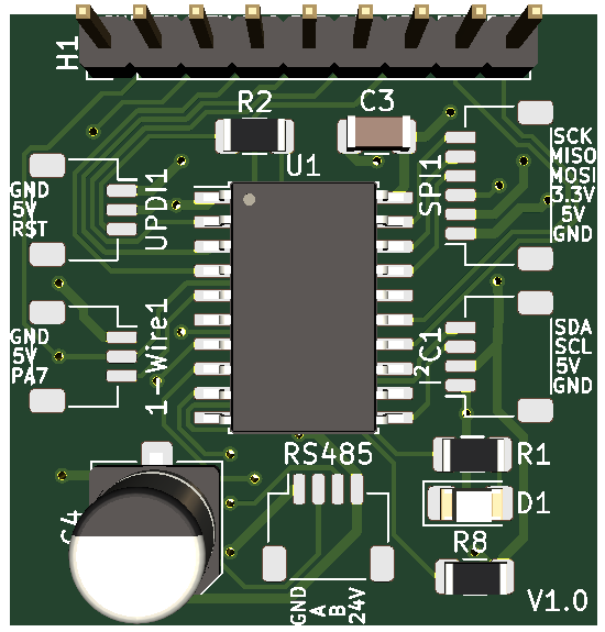 | 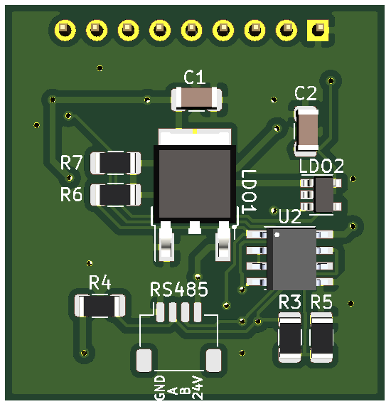 |
The sensor hub leverages the very capable ATtiny3216 (arduino compatible!).
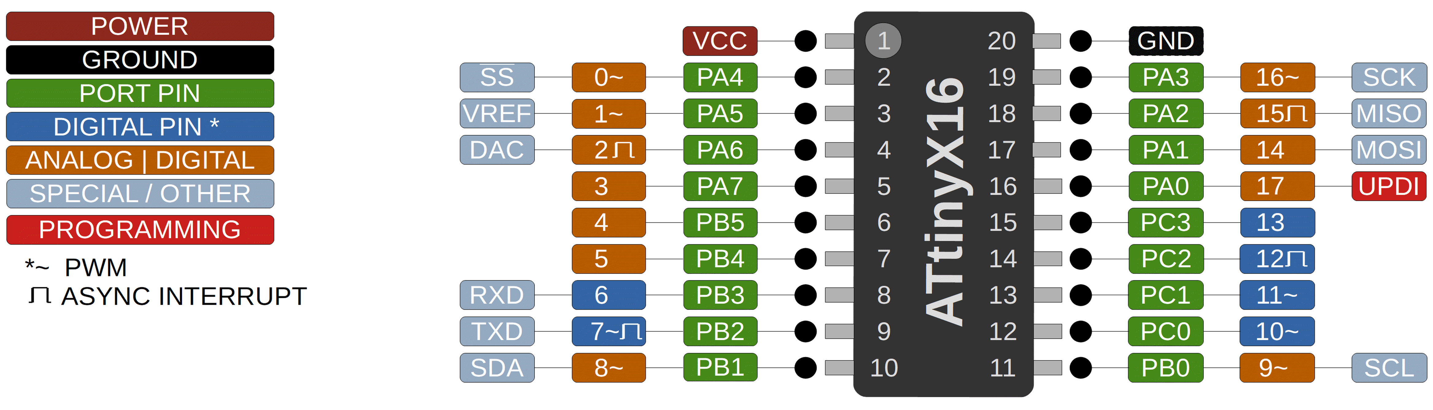
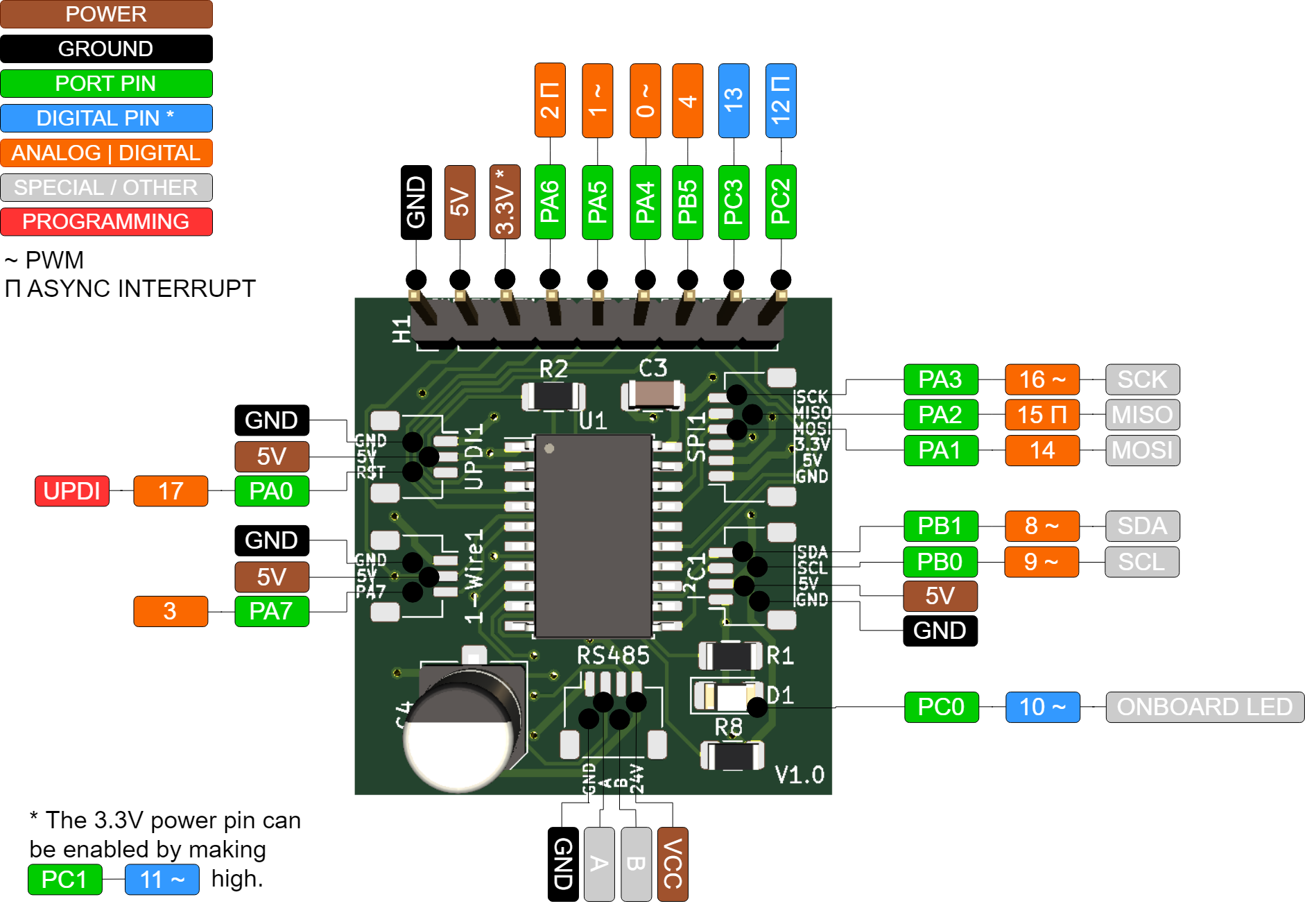
| Qty | Value | Footprint | References |
|---|---|---|---|
| 5 | 10k | Resistor_SMD:R_1206_3216Metric | R4, R5, R6, R7, R8 |
| 3 | 100u | Capacitor_SMD:C_1206_3216Metric | C1, C2, C3 |
| 2 | Conn_01x03 | Connector_JST:JST_SH_SM03B-SRSS-TB_1x03-1MP_P1.00mm_Horizontal | 1-Wire1, UPDI1 |
| 1 | 100u | Capacitor_SMD:CP_Elec_6.3x7.7 | C4 |
| 1 | 120 | Resistor_SMD:R_1206_3216Metric | R3 |
| 1 | 300 | Resistor_SMD:R_1206_3216Metric | R1 |
| 1 | 4.7k | Resistor_SMD:R_1206_3216Metric | R2 |
| 1 | ATtiny3216-S | Package_SO:SOIC-20W_7.5x12.8mm_P1.27mm | U1 |
| 1 | Conn_01x04 | Connector_JST:JST_XH_S4B-XH-A-1_1x04_P2.50mm_Horizontal | RS485 |
| 1 | Conn_01x04 | Connector_JST:JST_SH_SM04B-SRSS-TB_1x04-1MP_P1.00mm_Horizontal | I²C1 |
| 1 | Conn_01x06 | Connector_JST:JST_SH_SM06B-SRSS-TB_1x06-1MP_P1.00mm_Horizontal | SPI1 |
| 1 | Conn_01x9 | Connector_PinHeader_2.54mm:PinHeader_1x09_P2.54mm_Vertical | H1 |
| 1 | LD1086DT50TR | Package_TO_SOT_SMD:TO-252-2 | LDO1 |
| 1 | LED | LED_SMD:LED_1206_3216Metric_Pad1.42x1.75mm_HandSolder | D1 |
| 1 | MAX1487CSA+T | MAX1487CSA_T:SOIC127P600X175-8N | U2 |
| 1 | MIC5504-3.3YM5 | Package_TO_SOT_SMD:SOT-23-5 | LDO2 |
halleysfifthinc/AVCLAN-Mockingboard
Emulate a CD Changer on a Toyota AVC LAN network


DJM0/LoadShed
Off-grid 4-channel PWM load controller with regulated 12 V output from any 12–32 V battery. Sunrise/sunset + RTC scheduling, LiFePO₄ battery protection, dimming pots and an OLED. ATtiny3216 firmware + KiCad hardware.


alexanderenrique/smart_tbird
Smart Thunderbird vehicle electronics — ESP32 nodes, alternator delay, display, and tooling.


gugray/InterGalacticReceiver
Tune in to alien transmissions on a CRT screen! Shaders are involved.

It measures 30.7 × 34.3 mm and has 2 copper layers, 1.6 mm thick.
23 parts, built around the ATTINY3216-SF, MAX1487CSA+T and MIC5504-3.3YM5. The full list of its parts is on this page, with links to each part's symbol and footprint where PCBKit's library has them.
From the MichielVanwelsenaere/HomeAutomation.ModbusRtuSensorHub repository on GitHub, at the commit this page was made from: the board is src/ModbusRtuSensorHub.kicad_pcb. PCBKit opens the board in the browser, with nothing to install.
Its repository publishes it under the MIT licence: you may reuse it on that licence's terms (keep the author's notice, and for a copyleft licence share your changes alike).