2 layers92 × 110.6 mm

 Miceuz/SolarCampingLentern1
Solar powered camping lantern
Solar lantern is an open-source printed circuit board by Miceuz, from the Miceuz/SolarCampingLentern repository on GitHub. It is a 2-layer board of 153 × 123 mm with 65 parts on 36 nets, routed with 312 tracks and 389 vias.
It is built around the ATTINY441-SSU, MCP1664-E/OT and CN3791, with the RU20P7C among its other parts. Its parts include 21 resistors, 14 capacitors, 12 diodes, 3 ICs and 3 transistors. It belongs with the power boards and the AVR (ATmega, ATtiny) boards of this library.


I started seeing a lot of disposable electronic cigarettes being used. As everyone knows, those devices contain perfectly rechargeable LiPo battery. And I've seen them thrown away everywhere - on streets, in general waste thrash cans, etc. While a lot of my friends have successfully refilled juice and re-charged the battery, the devices are not built to last - heating coil dies after several re-uses anyway. I have decided to look for a way to recycle those batteries.
So I have decided to make a lantern for my camping needs and also investigate a product parameter space. The idea popped in to my mind during a summer music festival, actually. When you camp with your friends and need a bit of extra light in the camp at night. It was a sunny summer, so of course I had to have it solar powered. Provided unlimited supply of batteries, can it be self sufficient in it's power needs just from solar energy while still being manageable in camp environment?
It's always a good idea to check what's available at the market. Maybe there is a product on the market that does just that? Just a piece of my expenses, not worth spending my time?
I have gauged the amount of needed light from my Lumilight pocket torch I have lost and my "cyclope" torch from Decathlon I got this year. 100lm is not a huge amount of light but still not that bad - it's enough to see people and stuff around, human eye is logarithmic and adapts to low light conditions.
Run time is a modest guess from a festival scenario - you might need light from 11 at night to 3 in the morning, roughly.
Charging time is a lazy day camping, maybe I will remember to pull it out and put on a sun sometime. It's not full effective sun time, just general time the device spends in sun semi-kinda-charging.
There are devices that target the same light output I want. Some of these specifications are inferred as not all manufacturers provide all the information I needed. SunLight 100 does almost exactly what I want, but solar battery this size barely will produce 8.3Wh needed in 7h of charging time. All in all solar in all of these products seems to be a nice addition to USB charging, not the main power provider.
Also I have bought some not-so-cheap crap from local hardware store that pretended like it can do what I want, but solar battery was total crap in those, outputting mere single digit milli-amps.
Thus, I have easily convinced myself that this is well worth as a hobby project. Besides, had to use those batteries up! So, with the battery sourcing question sorted out, let's not think about price too much and look what happens if we push on the light output efficiency and solar input efficiency.
In the times of supply chain collapse, choosing a MMPT capable converter chip for storing solar energy to the battery was not an easy thing. They all are either not available or expensive. Luckily I have stumbled on this board by PC Tech featuring CN3791. Basically this project could have ended just there, as this board was all I needed - I have made my first prototype using it. Although I had to extract a bit more efficiency by having a dedicated led driver, also add some computer control to the thing.
It's one of the most efficient LEDs available at electronic distributors at the time. What's interesting and handy is that it's practically voltage controlled - it has a nice shallow IV curve. Provided you extract the heat from them though. They will happily do 100lm at 0.6W, the efficiency is even higher if you run them at half the rating. That's why I have doubled them up in my design.
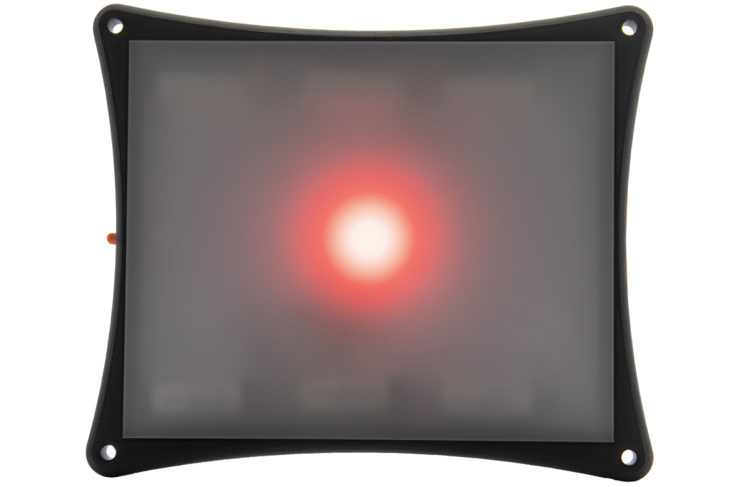
Also I have decided to throw in a red light source, to see if it might be usable too. Red light does not dazzle humans too much, so it makes a good low level standby light source for the night. I did not want to add additional complication of channel switching for led driver chip, thus decided to power red led directly from MCU pin.
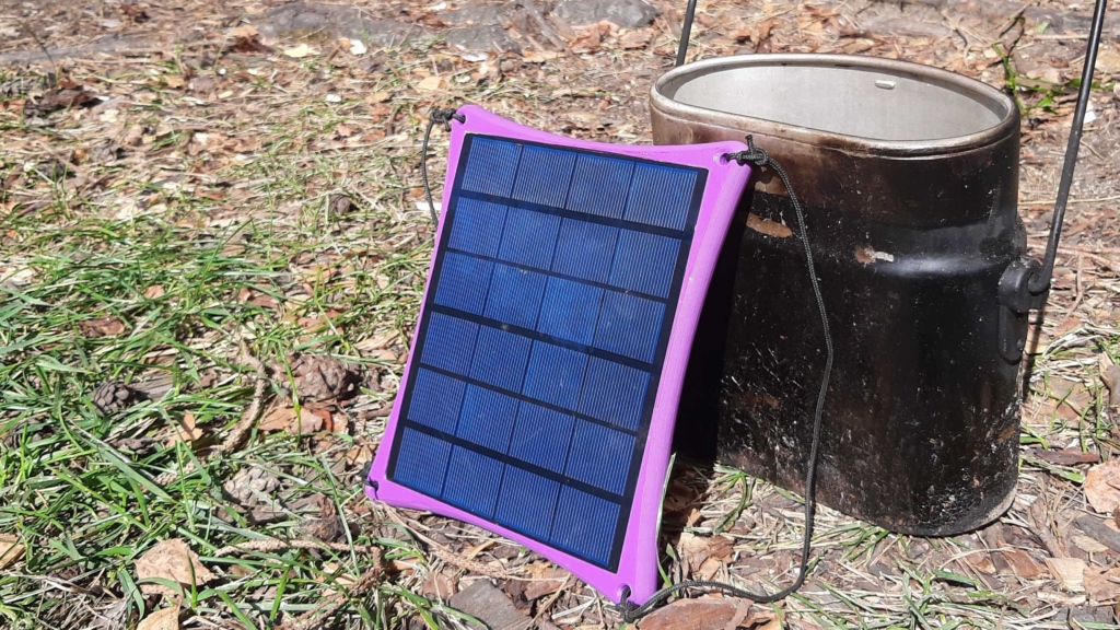
These panels, available at local suppliers, looked like a good trade-off between size and output power. Besides, not a lot to choose from, really. I have measured them and they were outputting the rated power, but it dropped drastically with non-perfect orientation to the sun, thus it has to be de-rated significantly. I have guesstimated MPPT point of the panel to be somewhere at 80% of it's open circuit voltage and measured about the same with a potentiometer hooked up to it.
If you replicate this design, be warned that battery failure is a risk to be considered!
Batteries are re-used from electronic cigarettes. I don't really know if they retain their safety ratings after they have been re-charged, but people around are re-charging them and I've heard of no fires happening.
They come with a protection board and I have tried shorting and over-discharging them - seem to work fine, also I've seen my friends ridiculously abusing them with high charge currents on par of 3C. Their longevity is to be proven though as they might not be optimized for a lot of re-charge cycles, but it seems their safety is on par with standards mandatory with CE marking. I am happy to delay their travel to a landfill or a recycler.
It has plenty of solar - 1h of perfect sunlight should provide enough of charge for 4 required hours. Seems to make sense to have more battery capacity, but there is a small trade-off with the weight. It will be interesting to experiment with battery sizes and see what run times are achievable.

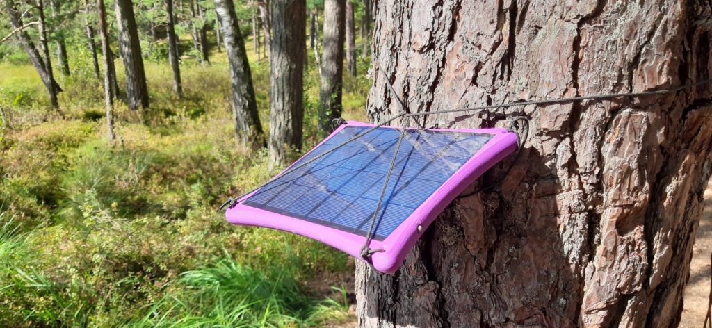
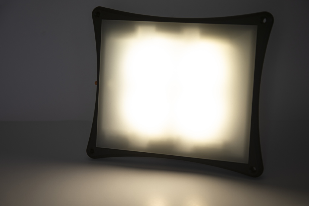
Size and shape of the device is dictated by the solar panel. Since I wanted a lot of solar power, I knew I will not be able to make it as compact as commercially available devices. Also mechanical side of things is not my strength, so I went for a simple flat panel. One of use cases for such a light would be as a coaster for a water bottle - that makes a pretty nice low effort table light. Also I've added 4 holes to attach the lantern with rope - to a branch or a tarp.
All assembly is glue based (blergh!). Batteries are glued to the PCB. PCB is glued and soldered to the solar panel. Both the solar panel and plexiglass are glued to a 3D printed plastic frame.
Considering the usage scenario, of course it should have some level of ingress protection. Provided all glue seams are tight (sic!), the only place for water to seep in is through a button hole. I am going to experiment with printing of the frame from flexible plastics and have the button hole closed, but for the first revision there's going to be a small seam between hole and plunger and IPX6 rated button behind it.
I have chosen my beloved attiny441 - I have a stock of them and I am used to them and it's a relief to spend some time in a simple naive world of 8-bit microcontrollers. It's pretty low power too.
Software functions:
| Item | Weight, g |
|---|---|
| 3.5W solar panel | 96 |
| Plexiglass | 73 |
| Frame | 56 |
| PCB 0.8mm | 36 |
| Battery 380mAh 7g, 3pack | 22 |
| Electronic components | 4 |
| Glue | 10 |
| Total | 297 |
| Item | Price, € |
|---|---|
| Solar panel | 13 |
| Electronic components | 6.3 |
| PCB | 5.1 |
| Frame | 2 |
| Plexiglass | 0.6 |
| Batteries | 0 |
| Total | 27 |
Prices are for a small batch of 10 units.
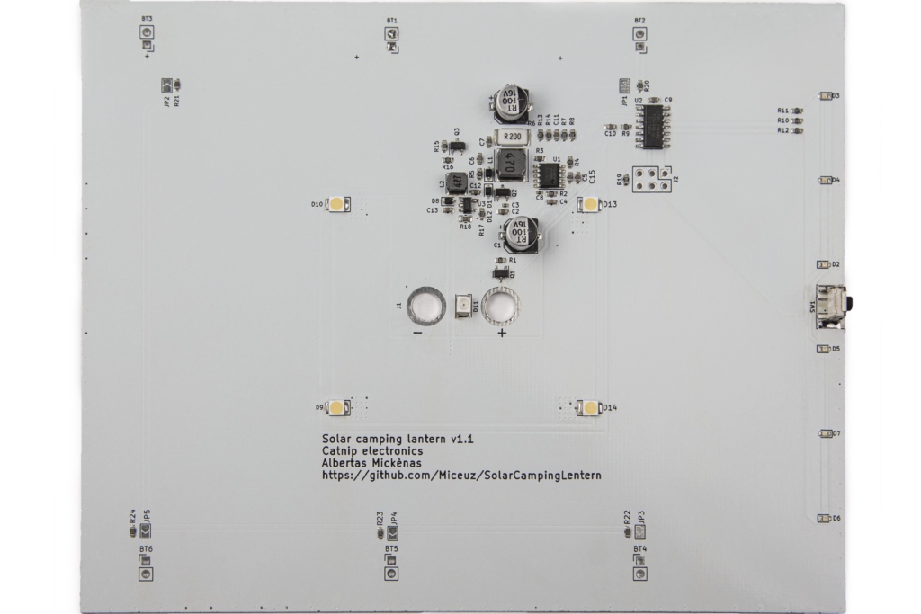
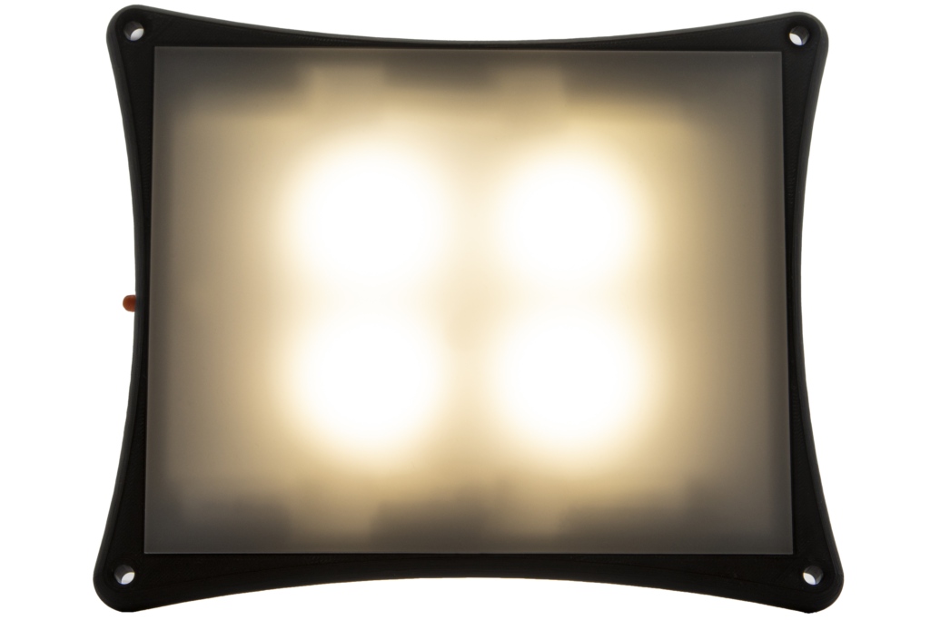
I took me 3 PCB iterations to get it right, I had to adjust a button position so it's easier to find in the dark, also I had to spread battery level indication leds along the edge so they would be distinguishable behind the plexiglass. Finally I have used 4 while leds instead of two, also spaced out as the single light source was a bit too strong.
Weight is a concern, but here I am limited to materials I have access to. I have made some improvements by using a 0.8mm PCB, maybe I can make the frame lighter, but the real limiting factors are solar pannel and plexiglass.
I have tried using the first prototype while camping at sunny autumn and it proved to be working very well. Working time with 870mAh battery was a little too short for long autumn evenings at full 100lm, but it was able to fully charge during the next day. Later I brought the panel to a rainy camping trip in December. Panel was barely charging the 5.5Ah battery, but it held almost two evenings allowing us to set up camp, prepare wood and chill under the red light in addition to fire. I think it's not much useful for rainy winter in Easter Europe, but it will be a perfect light for summer camping.
| Qty | Value | Footprint | References |
|---|---|---|---|
| 7 | 4u7 | Capacitor_SMD:C_0603_1608Metric | C2, C7, C9, C10, C11, C12, C13 |
| 6 | LED | Diode_SMD:D_0603_1608Metric | D2, D3, D4, D5, D6, D7 |
| 5 | 22k | Resistor_SMD:R_0603_1608Metric | R1, R3, R9, R15, R17 |
| 3 | 120 | Resistor_SMD:R_0603_1608Metric | R4, R5, R16 |
| 3 | 1k | Resistor_SMD:R_0603_1608Metric | R10, R11, R12 |
| 3 | Battery_Cell | Connector_PinHeader_2.54mm:PinHeader_1x02_P2.54mm_Vertical | BT1, BT2, BT3 |
| 3 | D_Schottky | Diode_SMD:D_SOD-323 | D1, D8, D12 |
| 3 | RU20P7C | Package_TO_SOT_SMD:SOT-23 | Q1, Q2, Q3 |
| 2 | 100n | Capacitor_SMD:C_0603_1608Metric | C4, C6 |
| 2 | 100u | Capacitor_SMD:CP_Elec_6.3x5.4_Nichicon | C1, C14 |
| 2 | 1M | Resistor_SMD:R_0603_1608Metric | R7, R8 |
| 2 | 1u | Capacitor_SMD:C_0402_1005Metric | C3, C8 |
| 2 | 43 | Resistor_SMD:R_0603_1608Metric | R20, R21 |
| 2 | LED | miceuz-lib:DS207 | D9, D10 |
| 2 | R | Resistor_SMD:R_0603_1608Metric | R13, R14 |
| 2 | SolderJumper_2_Open | Jumper:SolderJumper-2_P1.3mm_Open_TrianglePad1.0x1.5mm | JP1, JP2 |
| 1 | 0R2 | Resistor_SMD:R_2512_6332Metric | R6 |
| 1 | 100 | Resistor_SMD:R_0603_1608Metric | R19 |
| 1 | 220n | Capacitor_SMD:C_0603_1608Metric | C5 |
| 1 | 2R5 | Resistor_SMD:R_0805_2012Metric | R18 |
| 1 | 47u | Inductor_SMD:L_Coilcraft_XAL60xx_6.36x6.56mm | L1 |
| 1 | 4u7 | Inductor_SMD:L_Taiyo-Yuden_MD-4040 | L2 |
| 1 | 75k | Resistor_SMD:R_0603_1608Metric | R2 |
| 1 | ATtiny441-SS | Package_SO:SOIC-14_3.9x8.7mm_P1.27mm | U2 |
| 1 | AVR-ISP-6 | Connector_PinHeader_2.54mm:PinHeader_2x03_P2.54mm_Vertical | J2 |
| 1 | CN3791 | Package_SO:SSOP-10_3.9x4.9mm_P1.00mm | U1 |
| 1 | LOGO | miceuz-lib:catnip | G*** |
| 1 | MCP1664 | Package_TO_SOT_SMD:SOT-23-5 | U3 |
| 1 | PV | Connector_PinHeader_2.54mm:PinHeader_1x02_P2.54mm_Vertical | J1 |
| 1 | RED LED | LED_SMD:LED_PLCC-2 | D11 |
| 1 | SW_Push | Button_Switch_SMD:SW_Push_1P1T_NO_6x6mm_H9.5mm | SW1 |
The 64 most common of 65 parts.

punkfab/pcb-corpus
235 real KiCad boards from open-source hardware repositories, prepared as a placement and routing benchmark

Miceuz/i2c-moisture-sensor
I2C based soil moisture sensor

Miceuz/rs485-moist-sensor
Digital (RS485 - based) soil moisture and temperature sensor


Miceuz/rs485-breakout
A tiny development board to quickly prototype RS485/Modbus devices
It measures 153 × 123 mm and has 2 copper layers, 0.8 mm thick.
65 parts, built around the ATTINY441-SSU, MCP1664-E/OT, CN3791 and RU20P7C. The full list of its parts is on this page, with links to each part's symbol and footprint where PCBKit's library has them.
From the Miceuz/SolarCampingLentern repository on GitHub, at the commit this page was made from: the board is solar_lantern/solar_lantern.kicad_pcb and its schematic solar_lantern/battery.kicad_sch. PCBKit opens the board in the browser, with nothing to install.
Its repository states no licence, so its author keeps all rights: ask Miceuz before reusing the design.