

2 layers129.9 × 63.6 mm
Traeger rev 2.3.0.kicad pro
jazzmonger/Traeger-PID-Controller
Traeger Smoker/Grill Controller based on an
45 parts36
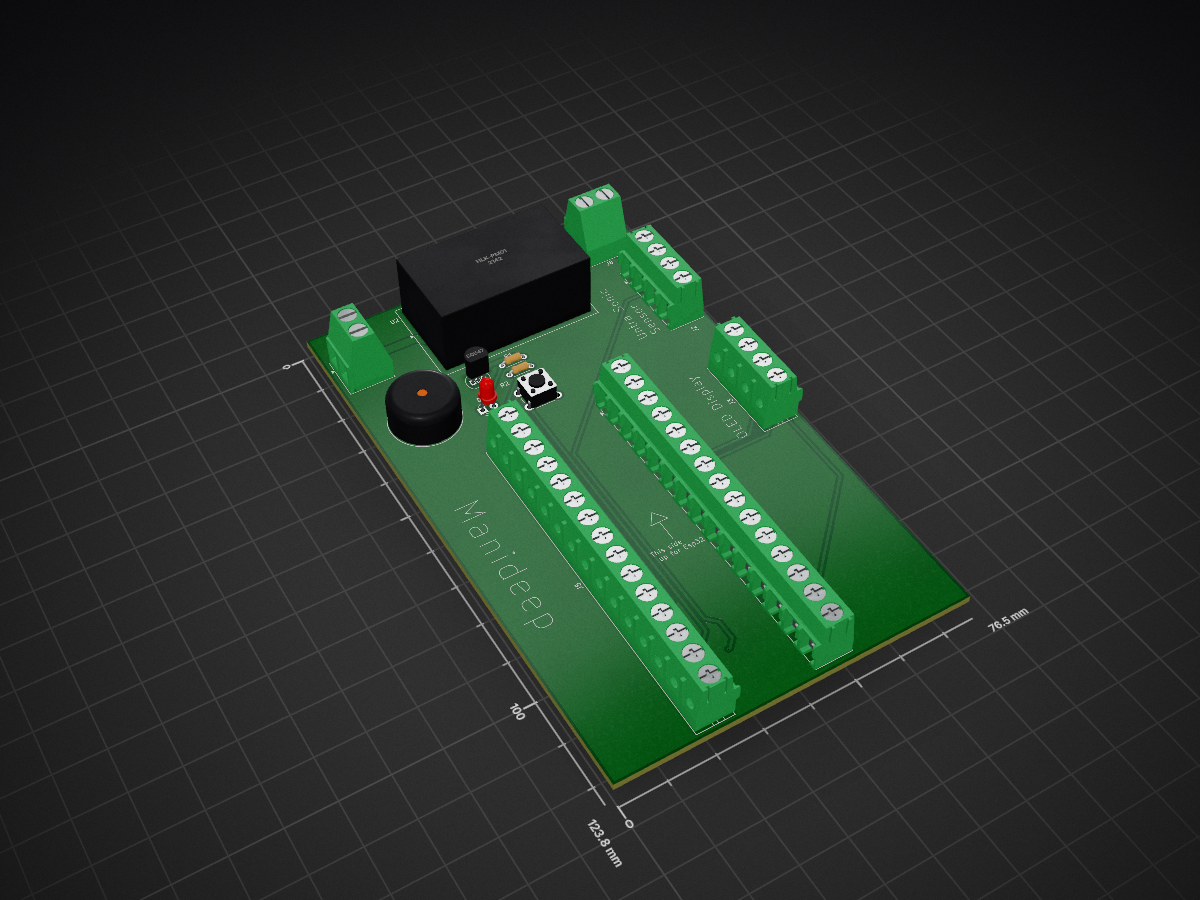
 Manideep136/Water-Level-Indicator
This project is an ESP32-based Water Level Indicator PCB designed to monitor the water level in a tank using an ultrasonic sensor and provide visual and audible alerts.
Water Level Indicator is an open-source printed circuit board by Manideep136, from the Manideep136/Water-Level-Indicator repository on GitHub. It is a 2-layer board of 76.5 × 123.8 mm with 13 parts on 35 nets, routed with 77 tracks and 2 vias.
It is built around the HLK-PM01 and BC547. Its parts include 6 connectors, 2 resistors, 1 IC, 1 diode and 1 transistor.
Project Overview
This project is an ESP32-based Water Level Indicator PCB designed to monitor the water level in a tank using an ultrasonic sensor and provide visual and audible alerts.
The PCB is designed in KiCad and provides connections for an ESP32 DevKit V1 (30-pin), ultrasonic sensor, OLED display, buzzer, LED indicator, push button, and power supply.
The ESP32 processes the distance measured by the ultrasonic sensor and determines the approximate water level. The status can be displayed on an OLED and indicated using LEDs and a buzzer.
Features ESP32 DevKit V1 based controller Ultrasonic water-level measurement OLED display interface using I²C LED status indication Buzzer alarm for high/critical water level Push-button input Transistor-driven buzzer circuit Removable ESP32 module Through-hole mounting for ESP32 headers External 5 V DC power input Designed using KiCad PCB layout suitable for prototype/college project development
🚀 Working Principle The ultrasonic sensor sends an ultrasonic pulse toward the water surface. The reflected signal is received by the sensor. The ESP32 calculates the distance to the water surface. The water level is calculated from the tank dimensions. The current water-level status can be displayed on the OLED. LEDs provide visual status indication. The buzzer provides an audible warning when the water reaches a defined critical level. The push button provides an additional user-control interface. 🔧 Future Improvements
Possible future versions can include:
Automatic water pump control Wi-Fi monitoring Mobile/web dashboard MQTT/ThingsBoard integration Water-level percentage calculation Multiple tank monitoring Low-water warning Overflow protection Relay/SSR output Capacitive water-level sensing PCB-mounted voltage regulator and protection circuit ⚠️ Important Design Notes Verify the exact ESP32 DevKit V1 dimensions before PCB manufacturing. Verify the 25.40 mm header row spacing against the physical ESP32 board. Use 2.54 mm pitch headers. Use appropriate voltage-level protection for a 5 V ultrasonic ECHO signal. Keep sensor wiring away from noisy/high-current traces. Use an external certified DC power supply for the prototype. Check ERC and DRC before generating Gerber files. Verify all connector pinouts before manufacturing. 📜 License
This project is intended for educational, academic, and personal development purposes.
Feel free to modify and improve the design for your own projects.
| Qty | Value | Footprint | References |
|---|---|---|---|
| 2 | Conn_01x15_Pin | TerminalBlock:TerminalBlock_MaiXu_MX126-5.0-15P_1x15_P5.00mm | J5, J6 |
| 2 | R | Resistor_THT:R_Axial_DIN0204_L3.6mm_D1.6mm_P5.08mm_Horizontal | R1, R2 |
| 2 | Screw_Terminal_01x02 | TerminalBlock_Phoenix:TerminalBlock_Phoenix_MKDS-1,5-2-5.08_1x02_P5.08mm_Horizontal | J7, J8 |
| 1 | BC547 | Package_TO_SOT_THT:TO-92_Inline | Q1 |
| 1 | Buzzer | Buzzer_Beeper:Buzzer_15x7.5RM7.6 | BZ1 |
| 1 | Conn_01x04_Pin | TerminalBlock:TerminalBlock_MaiXu_MX126-5.0-04P_1x04_P5.00mm | J2 |
| 1 | HLK-PM01 | Converter_ACDC:Converter_ACDC_Hi-Link_HLK-PMxx | U2 |
| 1 | LED | LED_THT:LED_D3.0mm | D1 |
| 1 | SW_Push | Button_Switch_THT:SW_PUSH_6mm | SW1 |
| 1 | Screw_Terminal_01x04 | TerminalBlock:TerminalBlock_MaiXu_MX126-5.0-04P_1x04_P5.00mm | J3 |
jazzmonger/Traeger-PID-Controller
Traeger Smoker/Grill Controller based on an

haripradhap14/ESP32-4CH-Relay-Controller-
4-channel IoT relay controller using ESP32-WROOM-32E for home automation.


AdharTechnologies/ESP8266_D1_MINI_IoT_switch
kindly read this blog for full understanding: https://docs.google.com/document/d/e/2PACX-1vSAi6zmGvRynDwEvqRe5kNtlbvMZqgKHYD9E6emAaTxG17WCHXLFxFSK3p-E7R5uc0UGJ3i0j8vB/pub

ayannsinghhh/home-automation-esp32-pcb
This project is a custom-designed home automation PCB built using an ESP32, aimed at controlling multiple household appliances through relay switching.


HenryqueFarias16/AgroTron
Projeto de Automação agrícola com microcontrolador ESP12-E

Rocheez/arcade-light-switch
A simple light switch made from discrete components
It measures 76.5 × 123.8 mm and has 2 copper layers, 1.6 mm thick.
13 parts, built around the HLK-PM01 and BC547. The full list of its parts is on this page, with links to each part's symbol and footprint where PCBKit's library has them.
From the Manideep136/Water-Level-Indicator repository on GitHub, at the commit this page was made from: the board is Water Level Indicator/Water Level Indicator.kicad_pcb and its schematic Water Level Indicator/Water Level Indicator.kicad_sch. PCBKit opens the board in the browser, with nothing to install.
Its repository states no licence, so its author keeps all rights: ask Manideep136 before reusing the design.