
2 layers69.8 × 52.7 mm
Stm32 lcd driver
sigma-prj/stm32-titan-lcd-driver-tm1621d-sample
Sample STM32 F030R8 NUCLEO board application to drive 7-Segments LCD using Titan TM1621D driver
15 partsCC0-1.0

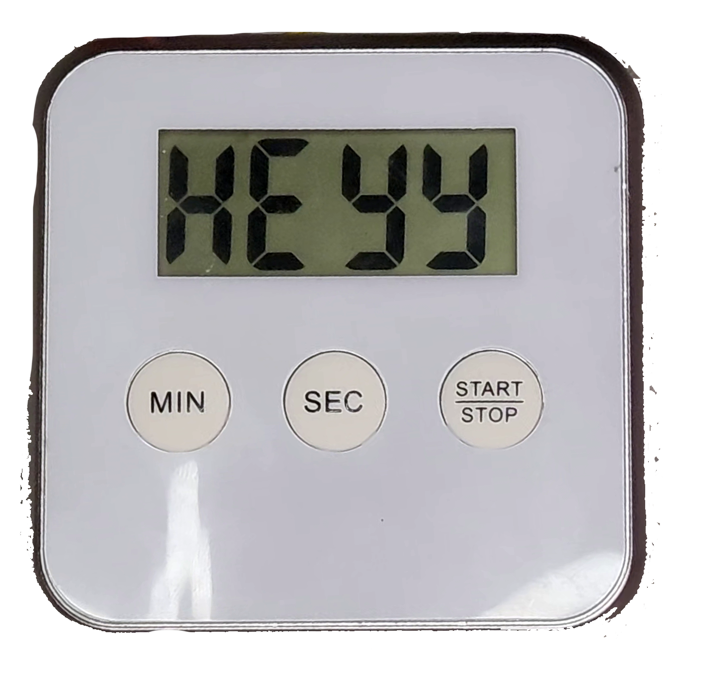
A replacement PCB board for common 4 digit 7 segment LCD kitchen timers.
Egg timer is an open-source printed circuit board by MakersFunDuck, from the MakersFunDuck/Common-Kitchen-Timer-With-LCD-Replacement-Board repository on GitHub, published under the GPL-3.0 licence. It is a 2-layer board of 51 × 43 mm with 25 parts on 39 nets, routed with 307 tracks and 48 vias.
It is built around the ATTINY13A-SU, ESP-12E and TM1621D, with the AMS1117-3.3 among its other parts. Its parts include 5 resistors, 5 ICs, 5 connectors, 4 capacitors and 3 switches. It belongs with the lEDs and displays boards and the ESP8266 and AVR (ATmega, ATtiny) boards of this library.


A replacement PCB board for common 4 digit 7 segment LCD kitchen timers
It uses a cheap TM1621D LCD driver. You can solder either Attiny13A, or ESP12E module.
The "Print" function can print out supported letters on the screen. However it is not optimised for memory constains for Attiny13A.
Folder descriptions:
Datasheets: Where datasheets of the components are located (also translations from Chinese)
Fabrication files: Gerber files. You can just upload those to any PCB manufacturer website to get your PCB.
Firmware: Code examples which is written using Arduino framework.
KiCAD files: KiCAD schematics and PCB files
Schematics and Layout files: PDF files for the PCB and Schematics.
If you want to use another LCD, or make your own PCB designs, I explained them in a video if you are interested. https://youtu.be/JNZbfLtlbZA
| Qty | Value | Footprint | References |
|---|---|---|---|
| 4 | Conn_01x01 | Connector_PinHeader_2.00mm:PinHeader_1x01_P2.00mm_Vertical | J2, J3, J4, J5 |
| 3 | 1k | Resistor_SMD:R_0805_2012Metric_Pad1.20x1.40mm_HandSolder | R1, R2, R4 |
| 3 | SW_Push | lcd:contact pad | SW1, SW2, SW3 |
| 2 | 100nF | Capacitor_SMD:C_0805_2012Metric_Pad1.18x1.45mm_HandSolder | C2, C4 |
| 2 | 10uF | Capacitor_SMD:C_0805_2012Metric_Pad1.18x1.45mm_HandSolder | C1, C3 |
| 1 | 0Ω | Resistor_SMD:R_0805_2012Metric_Pad1.20x1.40mm_HandSolder | R5 |
| 1 | 1K | Resistor_SMD:R_0805_2012Metric_Pad1.20x1.40mm_HandSolder | R3 |
| 1 | AMS1117-3.3 | Package_TO_SOT_SMD:SOT-223-3_TabPin2 | U4 |
| 1 | ATtiny13A-S | Package_SO:SOIC-8W_5.3x5.3mm_P1.27mm | U5 |
| 1 | Buzzer | Buzzer_Beeper:Buzzer_12x9.5RM7.6 | BZ1 |
| 1 | Conn_01x05 | Connector_PinHeader_2.00mm:PinHeader_1x05_P2.00mm_Vertical | J1 |
| 1 | ESP-12E | RF_Module:ESP-12E | U1 |
| 1 | LOGO | lcd:duck | G*** |
| 1 | R_Potentiometer | Potentiometer_THT:Potentiometer_Runtron_RM-065_Vertical | RV1 |
| 1 | TM1621D | Package_SO:SOIC-24W_7.5x15.4mm_P1.27mm | U2 |
| 1 | bare-lcd | lcd:bare-lcd-footprint12 | U3 |
sigma-prj/stm32-titan-lcd-driver-tm1621d-sample
Sample STM32 F030R8 NUCLEO board application to drive 7-Segments LCD using Titan TM1621D driver

andykarpov/karabas-pro
FPGA based retrocomputer with FDD and HDD controllers

iotmakervn/iot-wifi-uno-hw
Open hardware ESP8266 Uno board - Internet Of Things WiFi Uno

andrewngai/HomekitKnock
This repo is the resources for the project on https://youtu.be/X5OxuFtGn0

BogdanTheGeek/ESP_RC
An Open-Source Transmitter/Receiver for RC Planes, Cars, Boats and more based on ESP-NOW

KushlaVR/models-heart
Можливості: Керування через WIFI з телефона або ПК 5 незалежних каналів (світлодіоди/сервомотори) 1 Н-міст для підключення мотора (піковий струм до 3А) Вмонтована BMS 1S та контроллер заряду Li-Ion акумулятора з…

atom-robotics-lab/ThermoGlow-Coaster
This project is an ESP12E based Temperature Controlled Smart Coaster. The project uses the following: ESP12E Module 12 x WS2812B SMD LEDs MLX90614 Temperature Sensor I2C Module Power Bank Charge-Boost Module for…

cyberstormdotmu/ESP12E-breakout
A simple and open source ESP12E/ ESP8266 breakout board. You will need an external programmer to program the module but most of the components required to run the module are present. Made with KiCad.
It measures 51 × 43 mm and has 2 copper layers, 4.69 mm thick.
25 parts, built around the ATTINY13A-SU, ESP-12E, TM1621D and AMS1117-3.3. The full list of its parts is on this page, with links to each part's symbol and footprint where PCBKit's library has them.
From the MakersFunDuck/Common-Kitchen-Timer-With-LCD-Replacement-Board repository on GitHub, at the commit this page was made from: the board is KiCAD files/egg-timer.kicad_pcb and its schematic KiCAD files/egg-timer.kicad_sch. PCBKit opens the board in the browser, with nothing to install.
Its repository publishes it under the GPL-3.0 licence: you may reuse it on that licence's terms (keep the author's notice, and for a copyleft licence share your changes alike).