
4 layers234 × 84 mm
Main panel
google/mozc-devices
Circuit diagrams and firmware source code for Gboard DIY keyboards
234 parts3kApache-2.0

 LeoMos10/uncomMonACROPAD
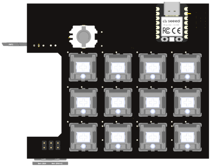
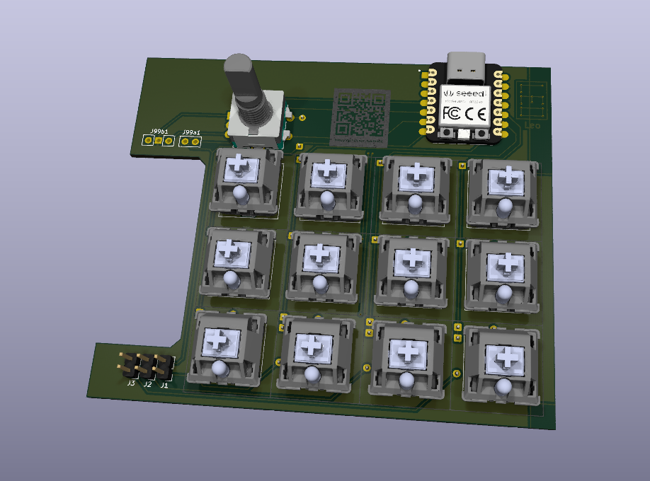
uncomMonACROPAD is a 12-key macropad with a rotary encoder (2 possible mount option: side and top) and an addressable RGB LED under every key.
HackPad is an open-source printed circuit board by LeoMos10, from the LeoMos10/uncomMonACROPAD repository on GitHub. It is a 2-layer board of 100 × 85 mm with 47 parts on 42 nets, routed with 235 tracks and 30 vias.
It is built around the SK6812MINI-E. Its parts include 28 diodes, 13 switches, 5 connectors and 1 IC.
uncomMonACROPAD is a 12-key macropad with a rotary encoder (2 possible mount option: side and top) and an addressable RGB LED under every key. The case is sandwich mount, 2 part 3D printed plus keycaps and knob and mounting hardware (M3 screws and heatset inserts). The PCB is a 2 layer designed in KiCad, and it runs on a Seeed Studio XIAO RP2040.
made for left handed and uncommon side mount layout.
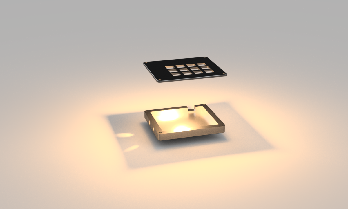
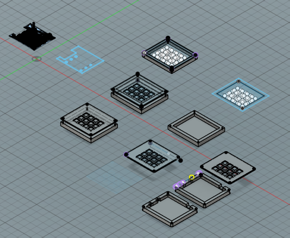
The case was designed in Fusion 360. It is a sandwich mount: a bottom tray with the USB-C cutout and side hole for side button, and a switch plate.
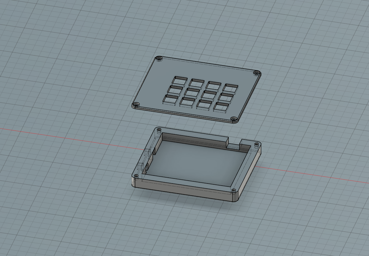
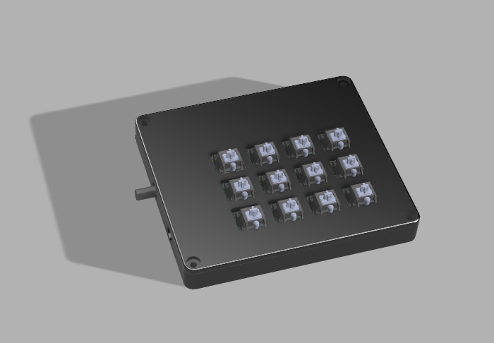
Assembled:
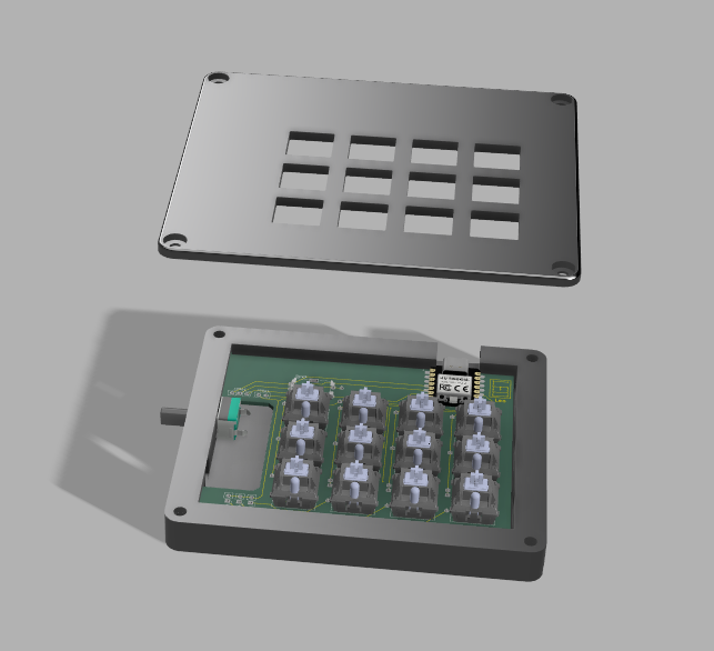
Taken apart, with the PCB sitting in the bottom tray:
The PCB was made in KiCad.
board:
interactive HTML mount guide (made with a KiCad extension)
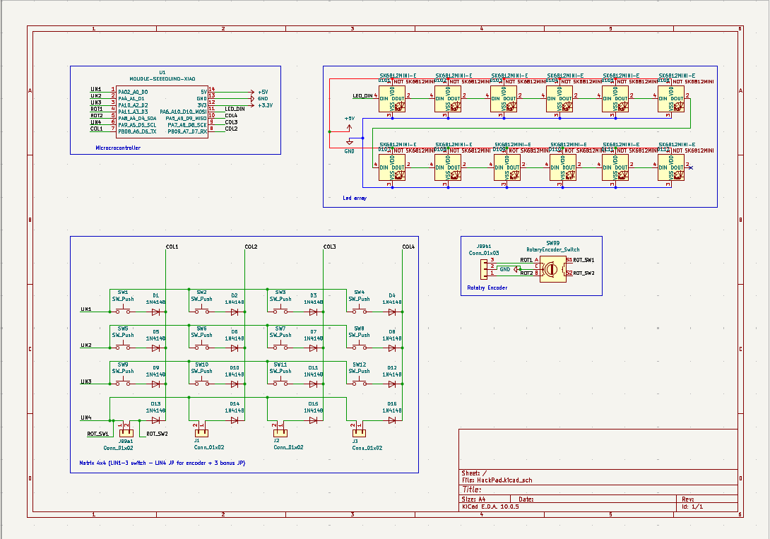
ERC: 0 errors.
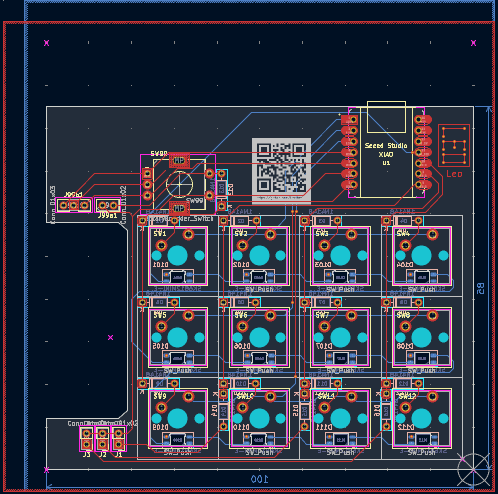
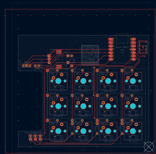
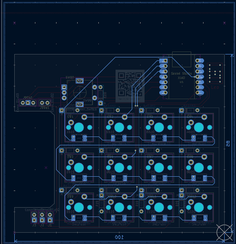
Front copper and back copper in the editor (red is F.Cu, blue is B.Cu):
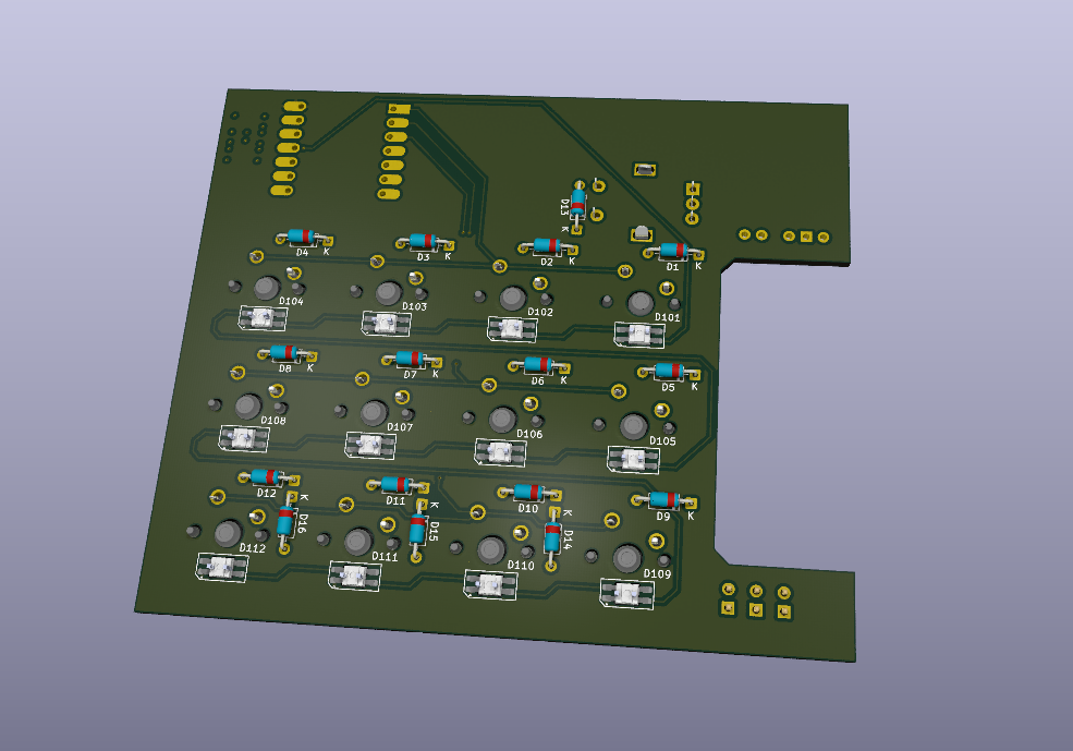
3D renders of the board:
the firmware used for now is KMK, for now I selected this because is a lot easier than QMK, because it doesnt have a toolchain (it isent compiled)
This hackpad uses a 4x4 matrix grid
| x | 1 | 2 | 3 | 4 |
|---|---|---|---|---|
| 1 | bt1 | bt2 | bt3 | bt4 |
| 2 | bt5 | bt6 | bt7 | bt8 |
| 3 | bt9 | bt10 | bt11 | bt12 |
| 4 | encder bt | jp1 | jp2 | jp3 |
[!TIP] most of the part come from the kit so they dont have links
| Quantity | Part | Link |
|---|---|---|
| 1 | Seeed Studio XIAO RP2040 | https://wiki.seeedstudio.com/XIAO-RP2040/ |
| 16 | 1N4148 diode | https://assets.nexperia.com/documents/data-sheet/1N4148_1N4448.pdf |
| 12 | Cherry MX style switches | |
| 12 | Keycaps | |
| 12 | SK6812MINI-E RGB LED | https://cdn-shop.adafruit.com/product-files/4960/4960_SK6812MINI-E_REV02_EN.pdf |
| 1 | EC11E rotary encoder with switch | |
| 3 | 2.54mm pin header 1x02, expansion for 3 extra switches (J1, J2, J3) | - |
| 1 | 2.54mm pin header 1x02, no GND(custom footprint) (J99A1) | - |
| 1 | 2.54mm pin header 1x03 (J99B1) | - |
| 1 | Rotary encoder knob | - |
| 4 | M3x5x4mm heatset inserts | |
| 4 | M3x16mm screws | |
| 1 | 3D printed case (PLA) | - |
| 1 | PCB (JLCPCB) | - |
| 1 | side button (optional, 65mm diameter) | - |
AI was never used for:
instead, it was used a little for:
a few things:
| Qty | Value | Footprint | References |
|---|---|---|---|
| 16 | 1N4148 | Diode_THT:D_DO-35_SOD27_P7.62mm_Horizontal | D1, D2, D3, D4, D5, D6, D7, D8, D9, D10, D11, D12, D13, D14, D15, D16 |
| 12 | SK6812MINI-E | LED_SMD:LED_SK6812MINI-E_3.2x2.8mm_P1.5mm_ReverseMount | D101, D102, D103, D104, D105, D106, D107, D108, D109, D110, D111, D112 |
| 12 | SW_Push | Button_Switch_Keyboard:SW_Cherry_MX_1.00u_PCB | SW1, SW2, SW3, SW4, SW5, SW6, SW7, SW8, SW9, SW10, SW11, SW12 |
| 3 | Conn_01x02 | Connector_PinHeader_2.54mm:PinHeader_1x02_P2.54mm_Vertical | J1, J2, J3 |
| 1 | Conn_01x02 | custom_pin:PinHeader_1x02_P2.54mm_Vertical_no_gnd | J99a1 |
| 1 | Conn_01x03 | custom_pin:PinHeader_1x03_P2.54mm_Vertical | J99b1 |
| 1 | MOUDLE-SEEEDUINO-XIAO | HackPad:XIAO-Generic-Hybrid-14P-2.54-21X17.8MM | U1 |
| 1 | RotaryEncoder_Switch | Rotary_Encoder:RotaryEncoder_Alps_EC11E-Switch_Vertical_H20mm | SW99 |
google/mozc-devices
Circuit diagrams and firmware source code for Gboard DIY keyboards

Bastardkb/Dilemma
The Dilemma is a vertical stagger low-profile keyboard with mods.

Pwnsat/FlatSat
Flatsat v1.0 is a hardware based platform for aerospace cybersecurity research

adamws/kicad-kbplacer
KiCad plugin for automatic keyboard's key placement and routing

imchipwood/dumbpad
Simple 4x4 numpad with rotary encoder. Powered by QMK via ATmega32u4 Pro Micro

makerforgetech/modular-biped
An open source framework for creating a bipedal modular companion robot.


It measures 100 × 85 mm and has 2 copper layers, 1.6 mm thick.
47 parts, built around the SK6812MINI-E. The full list of its parts is on this page, with links to each part's symbol and footprint where PCBKit's library has them.
From the LeoMos10/uncomMonACROPAD repository on GitHub, at the commit this page was made from: the board is PCB/HackPad.kicad_pcb and its schematic PCB/HackPad.kicad_sch. PCBKit opens the board in the browser, with nothing to install.
Its repository states no licence, so its author keeps all rights: ask LeoMos10 before reusing the design.