

2 layers88 × 78.3 mm

 LaboratorioGluon/ArduDCLoad3
Arduino Based Electronic DC Load.
CargaElectronica is an open-source printed circuit board by LaboratorioGluon, from the LaboratorioGluon/ArduDCLoad repository on GitHub, published under the GPL-2.0 licence. It is a 2-layer board of 88 × 94.3 mm with 56 parts on 41 nets, routed with 253 tracks and 14 vias.
It is built around the TL072 and IRFP460. Its parts include 24 resistors, 4 ICs, 3 diodes, 3 connectors and 3 switches. It belongs with the AVR (ATmega, ATtiny) boards of this library.
A configurable multipurpose DC Load board developed directly on Twitch
The values of the resistors can be calculated to adapt the PCB to your needs.
With defaul values máximum values are:
And this is how it looks:
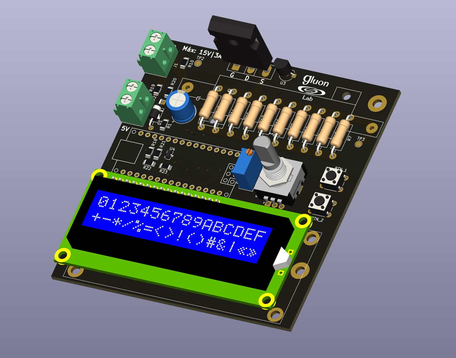
Here we will see how to customize the circuit for our need. The ADCL (ArduDCLoad) can be configure to mount a beefy TO-247 or small TO-220 MOSFETS. Also, it also contains the footprint for 10 resistors( L: 10mm, D: 3.6mm, P:15mm) or big chunky wirewound resistor (L:50mm, W:14mm).
Lets see how to adapt it to your need (we will calculate the values for the current values in the design)
Set what do you need for V_TEST and I_TEST. The circuit can only support around 5-6A máximum.
In our case
V_TEST = 15V I_TEST = 3A
The ideal values would be between 1 to 0.1 Ohms. The lower the current you expect, the bigget the value should be. In our case, for 3A, with 1 Ohm, we have 3V drop, so we can go with 1 Ohm. (We expect to test more than 3V)
| Qty | Value | Footprint | References |
|---|---|---|---|
| 6 | 1/1w | Resistor_THT:R_Axial_DIN0411_L9.9mm_D3.6mm_P15.24mm_Horizontal | R9, R11, R12, R14, R15, R16 |
| 4 | 1/1W | Resistor_THT:R_Axial_DIN0411_L9.9mm_D3.6mm_P15.24mm_Horizontal | R6, R7, R13, R17 |
| 3 | TestPoint | TestPoint:TestPoint_Pad_D2.0mm | TP1, TP2, TP3 |
| 2 | 1k | Resistor_SMD:R_1206_3216Metric_Pad1.30x1.75mm_HandSolder | R2, R21 |
| 2 | 330 | Resistor_SMD:R_1206_3216Metric_Pad1.30x1.75mm_HandSolder | R3, R8 |
| 1 | 1Meg | Resistor_SMD:R_1206_3216Metric_Pad1.30x1.75mm_HandSolder | R10 |
| 1 | 10k | Resistor_SMD:R_1206_3216Metric_Pad1.30x1.75mm_HandSolder | R20 |
| 1 | 10k; 1/4w | Resistor_SMD:R_1206_3216Metric_Pad1.30x1.75mm_HandSolder | R5 |
| 1 | 1Meg | Resistor_SMD:R_1206_3216Metric_Pad1.30x1.75mm_HandSolder | R24 |
| 1 | 1k5 | Resistor_SMD:R_1206_3216Metric_Pad1.30x1.75mm_HandSolder | R22 |
| 1 | 200 | Potentiometer_THT:Potentiometer_Bourns_3296W_Vertical | RV1 |
| 1 | 220 | Resistor_SMD:R_1206_3216Metric_Pad1.30x1.75mm_HandSolder | R25 |
| 1 | 33k | Resistor_SMD:R_1206_3216Metric_Pad1.30x1.75mm_HandSolder | R19 |
| 1 | 3k3 | Resistor_SMD:R_1206_3216Metric_Pad1.30x1.75mm_HandSolder | R4 |
| 1 | 470R | Resistor_SMD:R_1206_3216Metric_Pad1.30x1.75mm_HandSolder | R1 |
| 1 | 470uF | Capacitor_THT:CP_Radial_D8.0mm_P3.50mm | C1 |
| 1 | 680 | Resistor_SMD:R_1206_3216Metric_Pad1.30x1.75mm_HandSolder | R18 |
| 1 | AnalogRef | TestPoint:TestPoint_Pad_D2.0mm | TP4 |
| 1 | Arduino_Nano | Arduinos:arduino_nano | A1 |
| 1 | Btn.BCK | Button_Switch_THT:SW_PUSH_6mm_H4.3mm | SW3 |
| 1 | Btn.OK | Button_Switch_THT:SW_PUSH_6mm_H4.3mm | SW2 |
| 1 | D_Schottky | Diode_SMD:D_SOD-323_HandSoldering | D2 |
| 1 | FAN_OUTPUT | Connector_PinHeader_2.54mm:PinHeader_1x02_P2.54mm_Vertical | J3 |
| 1 | FanCtrl | TestPoint:TestPoint_Pad_D2.0mm | TP5 |
| 1 | IRFP460 | Package_TO_SOT_THT:TO-247-3_Vertical | Q1 |
| 1 | LED | LED_THT:LED_D5.0mm_Horizontal_O1.27mm_Z3.0mm | D3 |
| 1 | LM35-LP | Package_TO_SOT_THT:TO-92_Inline_Wide | U3 |
| 1 | LOGO | GluonLib:LogoGluon_25mm | G*** |
| 1 | LOGO | GluonLib:g | G*** |
| 1 | Pantalla_LCD_16x2_i2c | Connector_PinHeader_2.54mm:PinHeader_1x04_P2.54mm_Horizontal | U2 |
| 1 | Q_NMOS_GSD | Package_TO_SOT_SMD:SOT-23 | Q2 |
| 1 | Rotary_Encoder_Switch | Rotary_Encoder:RotaryEncoder_Alps_EC11E-Switch_Vertical_H20mm | SW1 |
| 1 | TL072 | Package_SO:SOIC-8_3.9x4.9mm_P1.27mm | U1 |
| 1 | TL431DBZ | Package_TO_SOT_SMD:SOT-23 | U4 |
| 1 | Voltage_IN | TerminalBlock:TerminalBlock_bornier-2_P5.08mm | J2 |
| 1 | Voltage_test | TerminalBlock:TerminalBlock_bornier-2_P5.08mm | J1 |
| 1 | Zener 5v | Diode_THT:D_A-405_P10.16mm_Horizontal | D1 |
The 49 most common of 56 parts.

Operationorange01/Flyback-Driver
driver for high voltage flyback transformer

Firestorm108/HFDRSSTC-Plasma-Flame-Generator-
A plasma flame generator, or high frequency dual resonant solid state tesla coil! It uses some really clever electronics to achieve this, and is a staple in plasma physics, being able to produce 4" flames at less than…

Firestorm108/mini-SSTC
A miniature CW SSTC driver! Fully through hole components and can be made for extremely cheap.

Ramprasad69975/ASIZSC-Converter-Design
KiCad schematic and PCB design of an Advanced Switched-Inductor Z-Source Converter (ASIZSC).


ohmtech-rdi/eurorack-blocks
Software to Hardware Prototyping for Eurorack using C++, Max/Gen~ or Faust

ctag-fh-kiel/ctag-tbd
CTAG TBD >>to be determined<< an extendible open source Eurorack sound module

plinkysynth/plinky_public
a public release of the plinky sw and hw
It measures 88 × 94.3 mm and has 2 copper layers, 1.6 mm thick.
56 parts, built around the TL072 and IRFP460. The full list of its parts is on this page, with links to each part's symbol and footprint where PCBKit's library has them.
From the LaboratorioGluon/ArduDCLoad repository on GitHub, at the commit this page was made from: the board is Schematics/CargaElectronica.kicad_pcb and its schematic Schematics/CargaElectronica.kicad_sch. PCBKit opens the board in the browser, with nothing to install.
Its repository publishes it under the GPL-2.0 licence: you may reuse it on that licence's terms (keep the author's notice, and for a copyleft licence share your changes alike).