
2 layers334.6 × 129.8 mm
Keyboard75 original
KevLe12/Vamora75
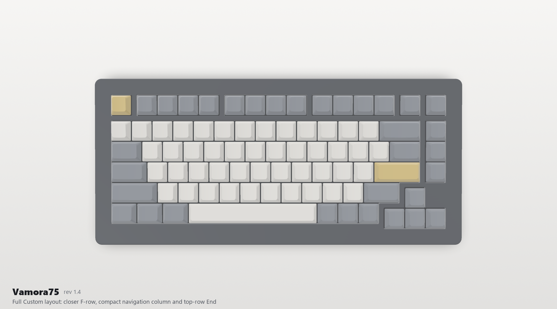
Revision 1.4 adopts all 82 key positions and widths from the supplied Custom layout, including the closer F-row, inward navigation column and End in the top row.
174 parts

 KevLe12/Vamora75
Revision 1.4 adopts all 82 key positions and widths from the supplied Custom layout, including the closer F-row, inward navigation column and End in the top row.
Vamora75 is an open-source printed circuit board by KevLe12, from the KevLe12/Vamora75 repository on GitHub. It is a 2-layer board of 315.6 × 129.8 mm with 208 parts on 139 nets, routed with 1,276 tracks and 274 vias.
It is built around the 1N4148W, 0402CG150J500NT and ABM8-272-T3, with the SMD0805-050 and TS-1187A-B-A-B among its other parts. Its parts include 82 diodes, 65 switches, 16 capacitors, 8 resistors and 1 crystal.


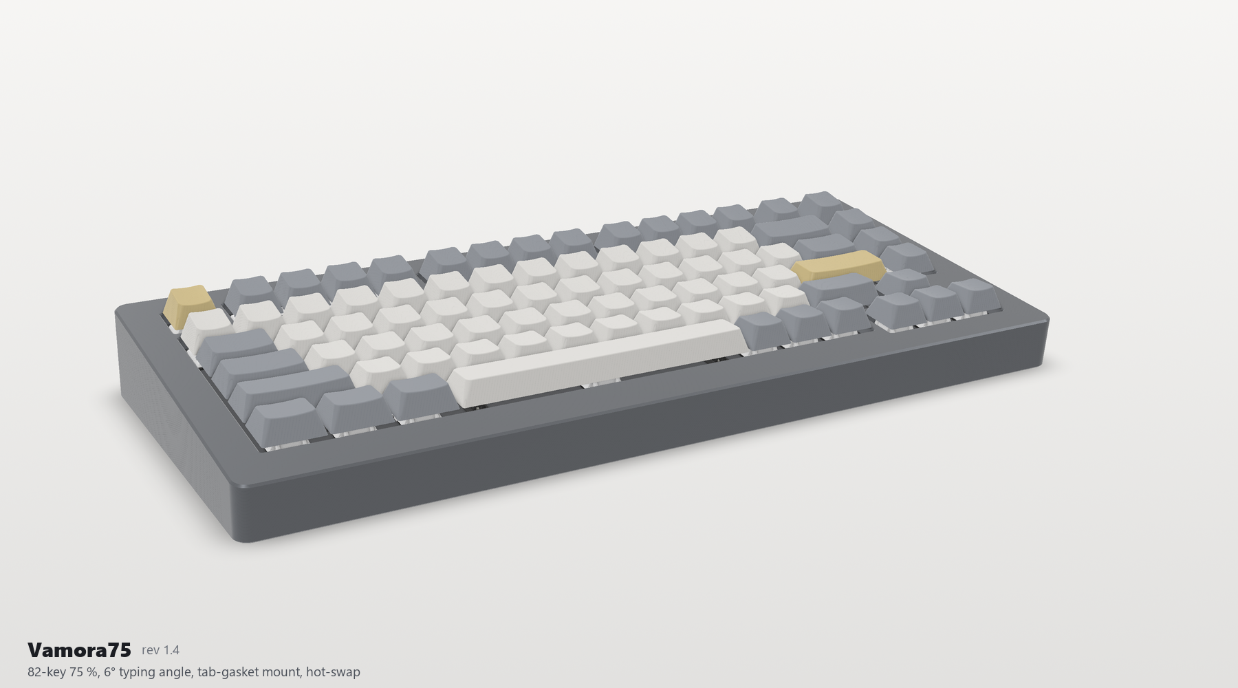
An 82-key 75 % mechanical keyboard with a 6° typing angle, a tab-gasket mount, hot-swap sockets and an on-board RP2040. Designed by Kevin Le, Sammy DeGraaff and Mohammed-Mehdi Hamdaoui.
Status: revision 1.4, prototype design checked in software, not built yet. ERC, DRC, schematic parity, plate DRC, 14 CAD interference checks and 30 firmware tests all pass (validation/STATUS.md). Build one prototype before a group order and work through the open items in DESIGN_REVIEW.md.
Revision 1.4 adopts all 82 key positions and widths from the supplied Custom layout, including the closer F-row, inward navigation column and End in the top row. USB-C is at the rear-left and the controller is below the spacebar. The USB pair requires fabricator confirmation of 90 ohm differential impedance; see fabrication notes.
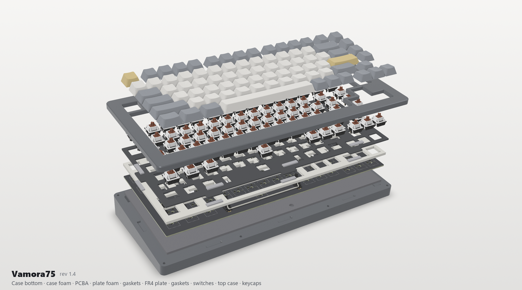
| Exploded | Top |
|---|---|
 |  |
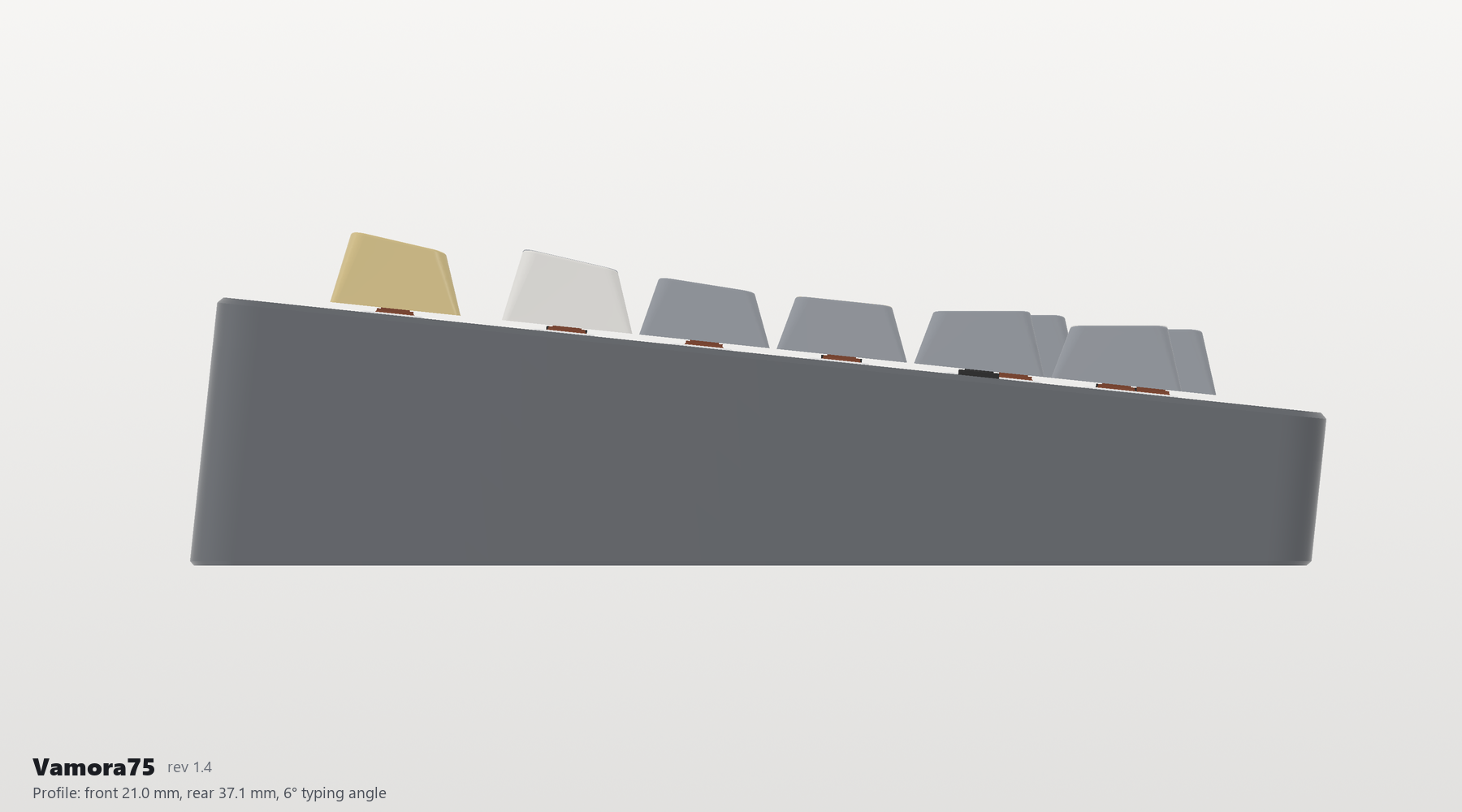
| Profile | Underside |
 |  |
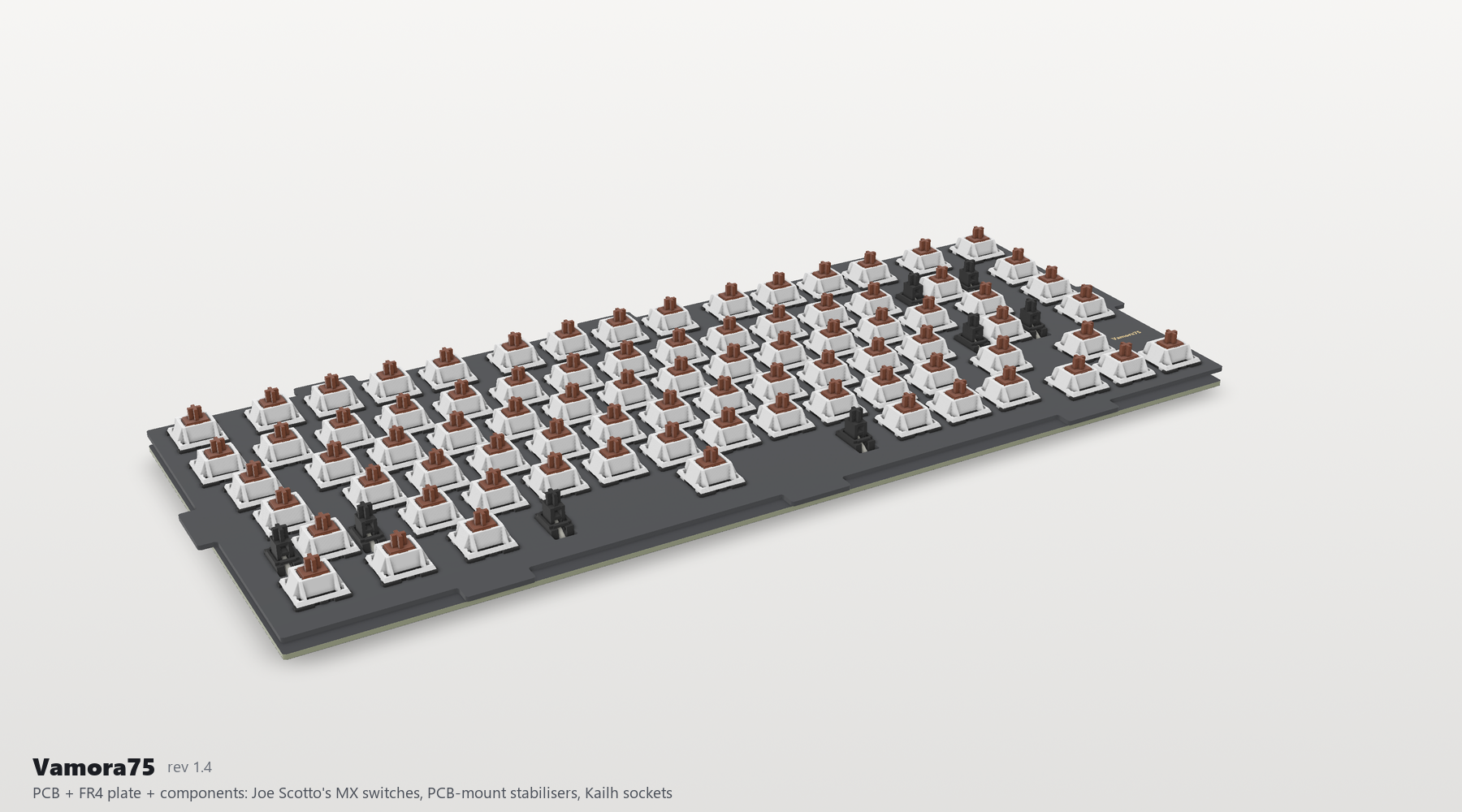
PCB + plate + components (no case): Joe Scotto's MX switches, the PCB-mount stabilisers, Kailh sockets and every SMD part (3D file, quick-look .glb):
| Front ("Vamora75" silkscreen) | Back (Nam Quốc Sơn Hà, designers, gold stabiliser rings) |
|---|---|
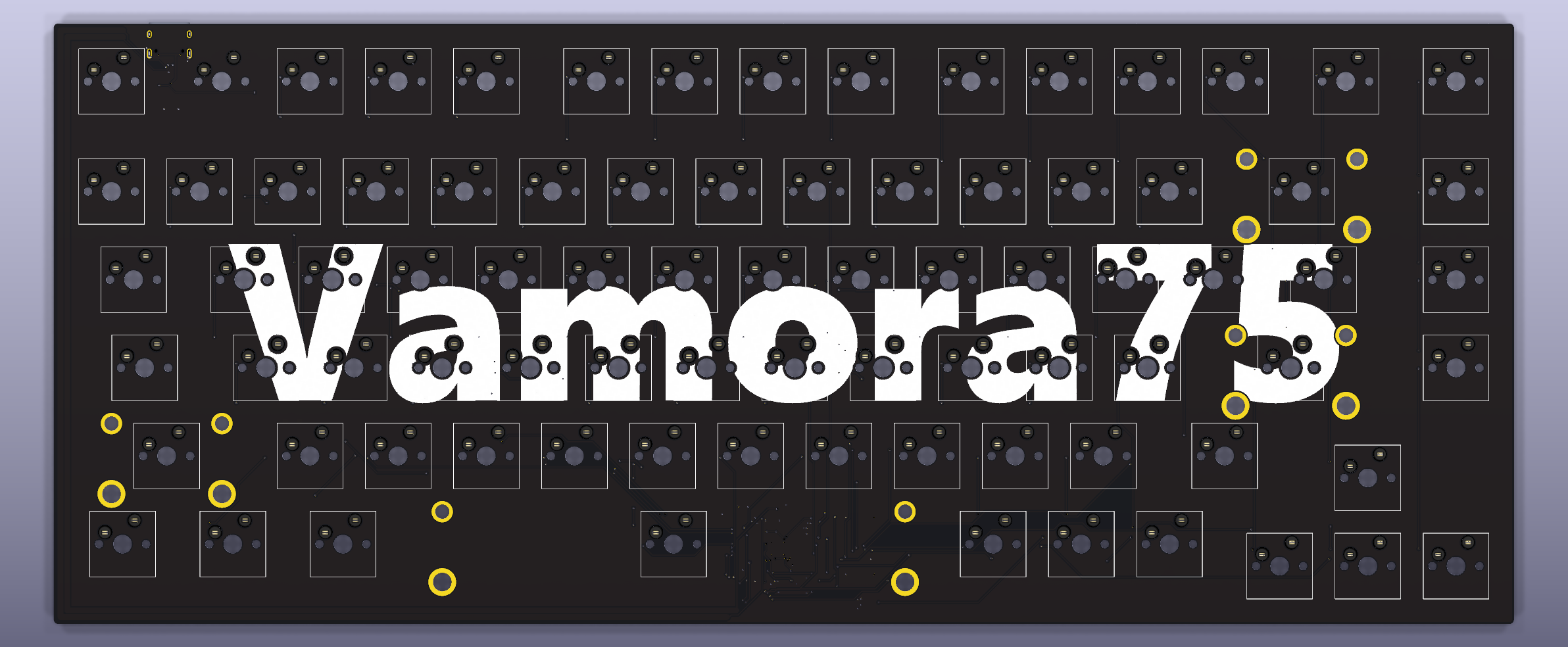 | 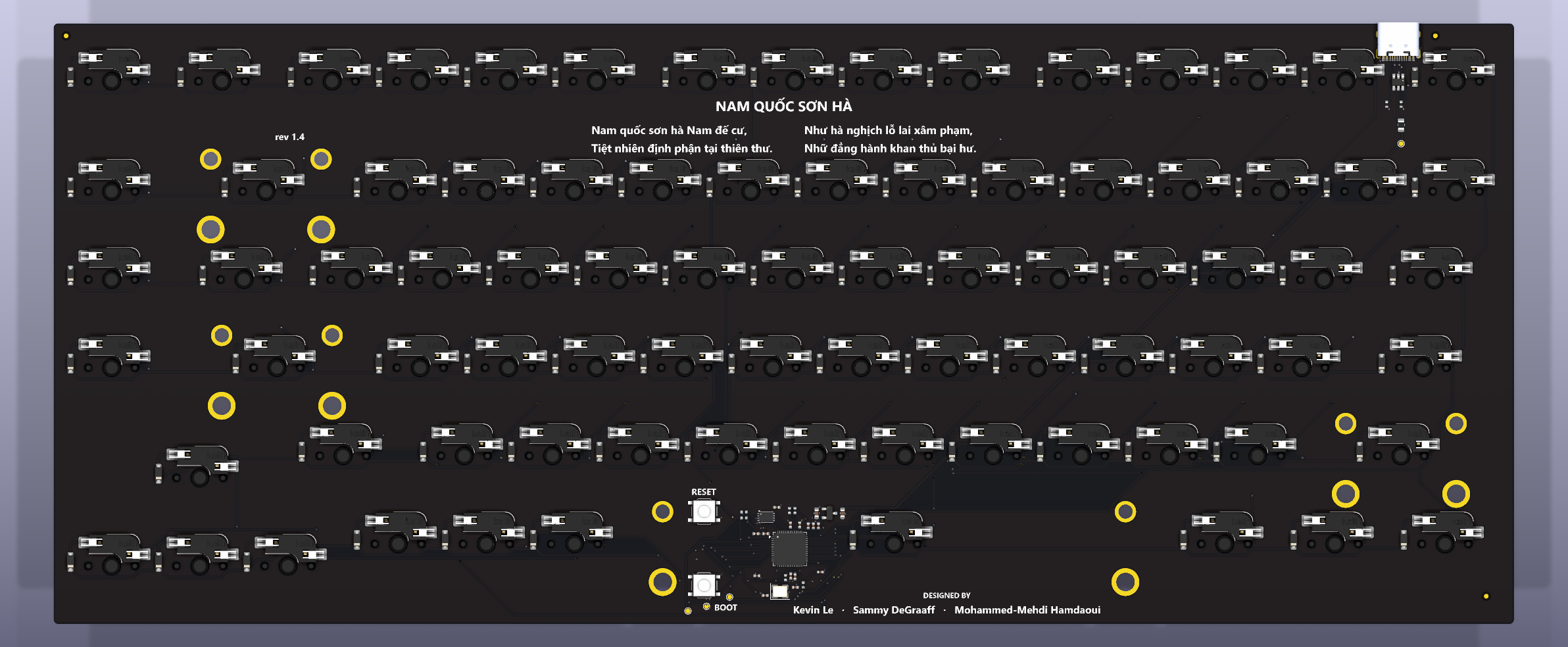 |
| With Joe Scotto's switch models | FR4 plate (name in gold ENIG, under the top case) |
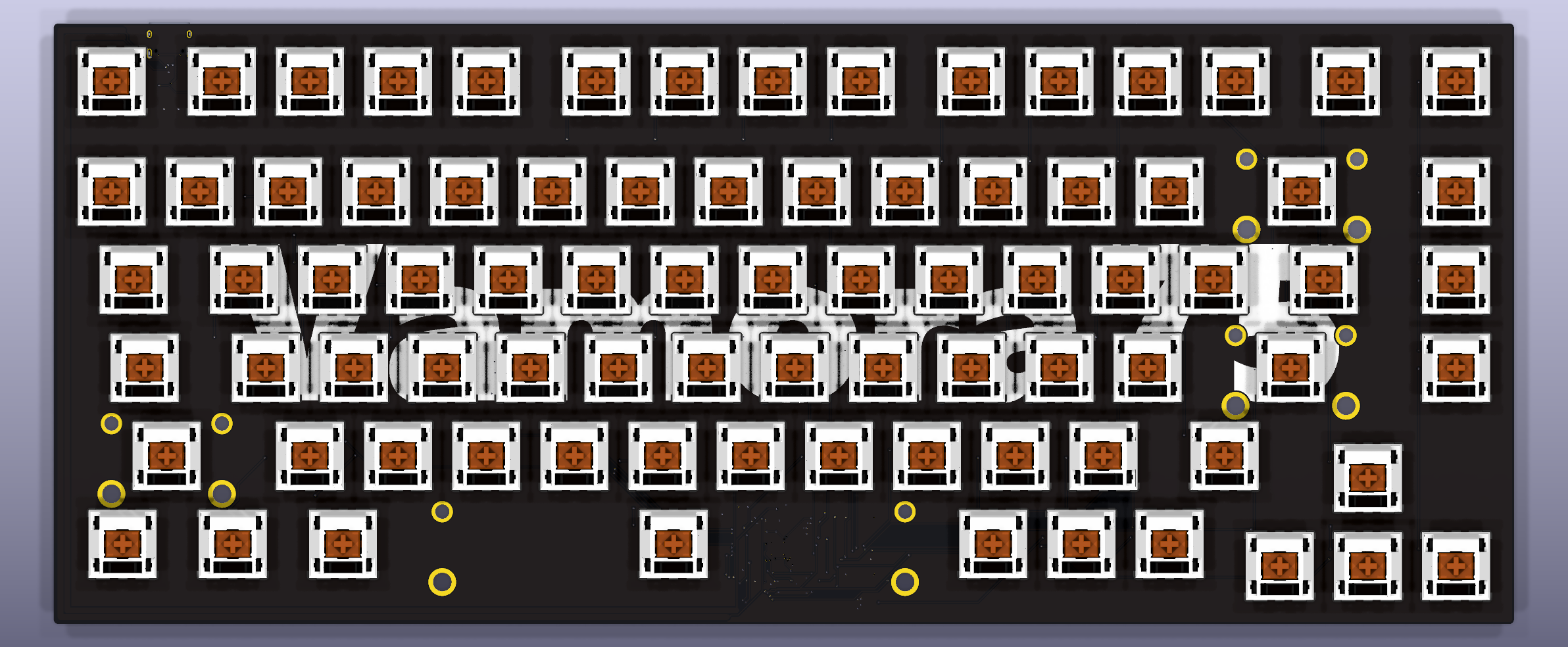 | 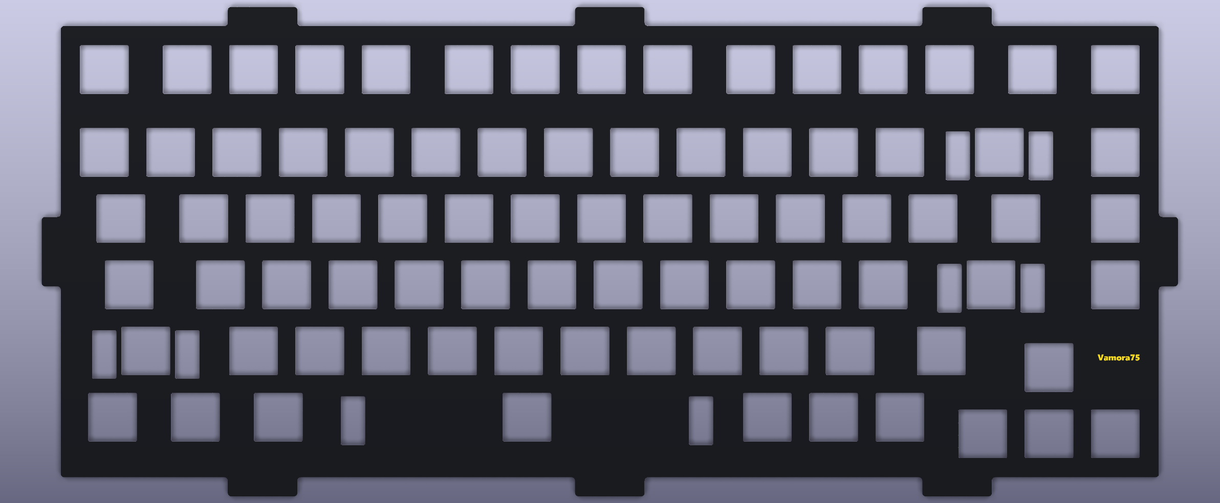 |
| File | Shows | Open with |
|---|---|---|
| Mechanical/Vamora75_assembly.step | The whole keyboard: case, gaskets, foams, plate, PCBA, switches, stabilisers, keycaps | FreeCAD, Fusion 360, Onshape, SolidWorks |
| Mechanical/Vamora75_PCB_plate.step | PCB + plate + every component, without the case | any STEP viewer |
| Mechanical/Vamora75_PCB_plate.glb | The same, as a light coloured model | Windows 3D Viewer, Blender, any web glTF viewer |
| Mechanical/Vamora75_PCBA.step | The PCBA only (KiCad export) | any STEP viewer |
| PCB/Vamora75.kicad_pro | Schematic and board; press Alt+3 for the 3D view | KiCad 10 |
Case parts, the plate and the soft parts are in Mechanical/ as STEP/STL/DXF.
| Layout | 82 keys: exploded 75 % Windows ANSI with an F-row in clusters, a Del/Home/PgUp/PgDn/End column, Custom-style arrow positions (0.25u gaps to RShift and RCtrl; 0.25u lower), 1.75u RShift and 6.25u space (layout) |
| Switches | Any MX-compatible switch, 3- or 5-pin, in Kailh CPG151101S11 hot-swap sockets (ScottoKicad Hotswap_MX footprints) |
| Stabilisers | PCB-mount screw-in: Backspace (2u), Enter and LShift (2.25u), Space (6.25u), standard orientation. Plated holes with 4.6 / 6.0 mm copper reinforcement rings; plate openings 7.0 x 14 mm |
| Controller | RP2040, W25Q16JV 2 MB flash, 12 MHz crystal (the Raspberry Pi Pico core circuit), BOOT and RESET buttons |
| USB | USB-C (HRO TYPE-C-31-M-12), USB 2.0 full speed, 5.1 kΩ CC resistors (C-C and A-C cables), USBLC6-2SC6 ESD protection, 0.5 A PTC fuse, XC6206 3.3 V LDO |
| Matrix | 6 x 16, COL2ROW, one 1N4148W per key |
| PCB | 315.56 x 129.83 mm, 2 layers, 1.6 mm, black solder mask, white silkscreen, ENIG. All SMT parts on the bottom (one-sided assembly), GND pour on both layers |
| Plate | FR4, 1.5 mm (1.6 mm also fits), black, 8 gasket tabs, optional flex cuts, "Vamora75" in gold ENIG |
| Mount | Tab-gasket sandwich: 16 gaskets of 20 x 4.5 x 2 mm at 20 % compression. PCB and plate float as one unit |
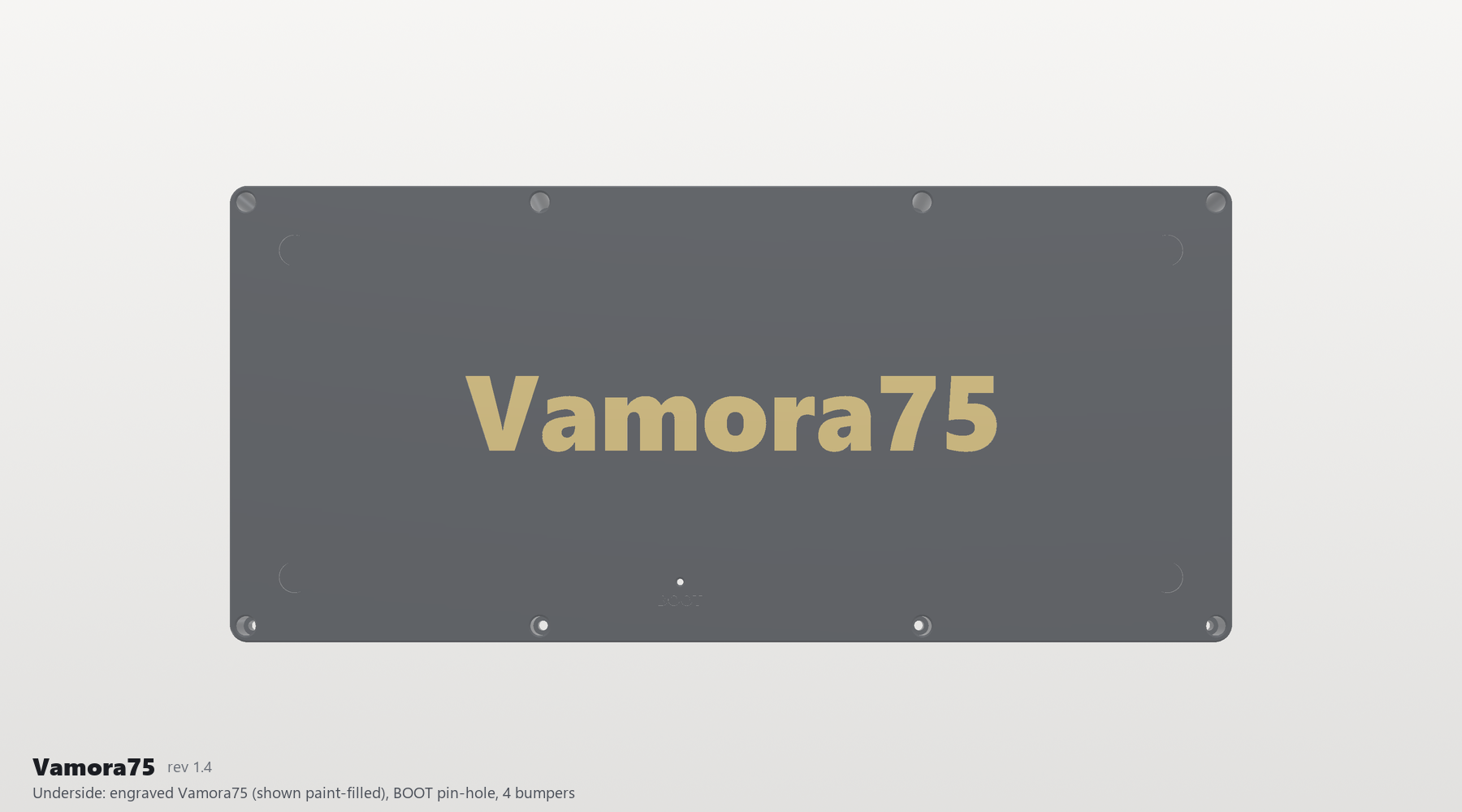
| Case | Two pieces, 6° typing angle, 20.98 mm high at the front and 37.06 mm at the rear, 339.56 x 156.73 mm. The top-case opening follows the key clusters (the case covers every gap between them). 8 M3 screws into heat-set inserts, "Vamora75" engraved underneath |
| Firmware | QMK + VIA, or CircuitPython |
Full list: BOM.csv. The PCBA parts are placed by JLCPCB from Vamora75_BOM_JLCPCB.csv and Vamora75_CPL_JLCPCB.csv; you only buy the kit items.
Kit: what to buy or make
| Item | Qty | Specification | Source / file |
|---|---|---|---|
| PCBA (this design) | 1 | 2-layer FR4 1.6 mm, black mask, ENIG, bottom-side SMT assembled | Manufacturing/PCB - JLCPCB/PCBWay |
| FR4 plate | 1 | 1.5 mm (1.6 mm fits), black mask, ENIG for the gold name | Manufacturing/Plate - any PCB fab |
| Case top | 1 | PETG/ASA print or CNC 6061 | Mechanical/Case |
| Case bottom | 1 | PETG/ASA print or CNC 6061 (solid wedge, 6 deg) | Mechanical/Case |
| MX-compatible switches | 82 | 3-pin or 5-pin | user choice |
| Keycaps | 82 | 1u x 71, 1.25u x 3, 1.5u x 2, 1.75u x 2, 2u x 1, 2.25u x 2, 6.25u x 1 | any MX set with a 75 % kit (1.75u RShift, 6.25u space) |
| PCB-mount screw-in stabilisers | 4 | 3 x 2u (Backspace, Enter, LShift) + 1 x 6.25u (Space) | Durock/Cherry/TX |
| Gaskets | 16 | 20 x 4.5 x 2 mm Poron 4701-50 or 40A silicone | Mechanical/Soft DXF |
| Case foam | 1 | 3 mm PE / Poron | Mechanical/Soft DXF |
| Plate foam (optional) | 1 | 3.5 mm Poron / PE, with stabiliser/wire windows | Mechanical/Soft DXF |
| Screws | 8 | M3 x 8 ISO 4762 socket head | |
| Heat-set inserts | 8 | M3 x 4 x 4.0 mm heat-set insert (printed top case; tap M3 if CNC) | |
| Dowel pins (split print only) | 5 | 3 x 12 mm steel dowel (or printed pin) | only for the 4-piece printed case |
| Bumpers | 4 | 10 x 3 mm silicone bumper | |
| USB-C cable | 1 | overmould <= 12.3 x 6.5 mm |
PCBA: parts on the board (197 placements, all on the bottom side)
| Part | Qty | Designators | Footprint | LCSC |
|---|---|---|---|---|
| 10uF CL10A106KP8NNNC | 2 | C1-C2 | C_0603_1608Metric | C19702 |
| 100nF CL05B104KO5NNNC | 10 | C3-C7, C9-C12, C15 | Capacitor_0402 | C1525 |
| 1uF CL05A105KA5NQNC | 2 | C13-C14 | Capacitor_0402 | C52923 |
| 15pF 0402CG150J500NT | 2 | C16-C17 | Capacitor_0402 | C1548 |
| 1N4148W | 82 | D1-D82 | Diode_SOD-123 | C81598 |
| 500mA SMD0805-050 | 1 | F1 | Fuse_0805_2012Metric | C66452 |
| HRO TYPE-C-31-M-12 | 1 | J1 | USB_C_HRO_TYPE-C-31-M-12 | C165948 |
| 5.1k 0402WGF5101TCE | 2 | R1-R2 | Resistor_0402 | C25905 |
| 27R 0402WGF270JTCE | 2 | R3-R4 | Resistor_0402 | C25100 |
| 10k 0402WGF1002TCE | 2 | R5, R7 | Resistor_0402 | C25744 |
| 1k 0402WGF1001TCE | 2 | R6, R8 | Resistor_0402 | C11702 |
| Kailh CPG151101S11 MX hot-swap socket | 82 | SW1-SW82 | Kailh_CPG151101S11 | C5156480 |
| BOOT TS-1187A-B-A-B | 1 | SW90 | SW_Push_1P1T_XKB_TS-1187A | C318884 |
| RESET TS-1187A-B-A-B | 1 | SW91 | SW_Push_1P1T_XKB_TS-1187A | C318884 |
| RP2040 | 1 | U1 | QFN-56-1EP_7x7mm_P0.4mm_EP3.2x3.2mm_ThermalVias | C2040 |
| USBLC6-2SC6 | 1 | U2 | ESD_SOT-23-6 | C7519 |
| XC6206P332MR | 1 | U3 | Voltage_SOT-23 | C5446 |
| W25Q16JVUXIQ | 1 | U4 | Winbond_USON-8-1EP_3x2mm_P0.5mm_EP0.2x1.6mm | C2843335 |
| 12MHz ABM8-272-T3 | 1 | Y1 | Crystal_SMD_3225-4Pin_3.2x2.5mm | C20625731 |
| Folder | Contents |
|---|---|
| PCB/ | KiCad 10 project: schematic, 2-layer board, project footprint library (ScottoKicad + KiCad stock) with 3D models, custom DRC rules |
| Plate/ | KiCad boards for ordering the FR4 plate as a PCB (standard and flex-cut) |
| Mechanical/ | Case (one-piece and 4-piece print split), plate DXF/STEP/STL, gasket and foam DXFs, assembly STEP, PCB + plate STEP/GLB, PCBA STEP, key positions |
| Manufacturing/ | JLCPCB-ready Gerbers/drill, BOM + CPL, schematic PDF, assembly drawing, plate Gerbers, kit BOM |
| Firmware/ | QMK + VIA source, VIA definition, CircuitPython, KLE layout |
| Artwork/ | The "Vamora75" name in SVG/PNG/DXF (NAME.md) |
| Previews/ | Renders |
| Source/ | Python generators for everything (build_all.py) |
| validation/ | ERC/DRC, mechanical, plate and firmware reports |
| Licenses/ | Third-party licenses and notices; see ATTRIBUTION.md |
| Reference/ | Input snapshots (Keyboard75, Aster75) |
Details: CHANGELOG.md.
Designed by Kevin Le, Sammy DeGraaff and Mohammed-Mehdi Hamdaoui (team Vamora).
Footprints and 3D models for the switches, sockets, stabilisers and several components are from Joe Scotto's ScottoKicad. Third-party data and licences: ATTRIBUTION.md and Licenses/.
Repository upload instructions: GITHUB_UPLOAD.md. Local archives and build intermediates are omitted from the GitHub snapshot. No project-wide license has been selected for the team's original work.
| Qty | Value | Footprint | References |
|---|---|---|---|
| 82 | 1N4148W | Vamora75:Diode_SOD-123 | D1, D2, D10, D11, D12, D13, D14, D15, D16, D17, D18, D19, D20, D21, D22, D23 +66 |
| 10 | 100nF | Vamora75:Capacitor_0402 | C3, C4, C5, C6, C7, C9, C10, C11, C12, C15 |
| 3 | Fiducial | Vamora75:Fiducial_1mm_Mask2mm | FID1, FID2, FID3 |
| 2 | 10k | Vamora75:Resistor_0402 | R5, R7 |
| 2 | 10uF | Vamora75:C_0603_1608Metric | C1, C2 |
| 2 | 15pF | Vamora75:Capacitor_0402 | C16, C17 |
| 2 | 1k | Vamora75:Resistor_0402 | R6, R8 |
| 2 | 1uF | Vamora75:Capacitor_0402 | C13, C14 |
| 2 | 27R | Vamora75:Resistor_0402 | R3, R4 |
| 2 | 5.1k | Vamora75:Resistor_0402 | R1, R2 |
| 1 | ' | Vamora75:Hotswap_MX_1.00u | SW56 |
| 1 | +3V3 | Vamora75:TestPoint_Pad_D1.0mm | TP2 |
| 1 | +5V | Vamora75:TestPoint_Pad_D1.0mm | TP4 |
| 1 | , | Vamora75:Hotswap_MX_1.00u | SW67 |
| 1 | - | Vamora75:Hotswap_MX_1.00u | SW26 |
| 1 | . | Vamora75:Hotswap_MX_1.00u | SW68 |
| 1 | / | Vamora75:Hotswap_MX_1.00u | SW69 |
| 1 | 0 | Vamora75:Hotswap_MX_1.00u | SW25 |
| 1 | 1 | Vamora75:Hotswap_MX_1.00u | SW16 |
| 1 | 12MHz | Vamora75:Crystal_SMD_3225-4Pin_3.2x2.5mm | Y1 |
| 1 | 2 | Vamora75:Hotswap_MX_1.00u | SW17 |
| 1 | 3 | Vamora75:Hotswap_MX_1.00u | SW18 |
| 1 | 4 | Vamora75:Hotswap_MX_1.00u | SW19 |
| 1 | 5 | Vamora75:Hotswap_MX_1.00u | SW20 |
| 1 | 500mA | Vamora75:Fuse_0805_2012Metric | F1 |
| 1 | 6 | Vamora75:Hotswap_MX_1.00u | SW21 |
| 1 | 7 | Vamora75:Hotswap_MX_1.00u | SW22 |
| 1 | 8 | Vamora75:Hotswap_MX_1.00u | SW23 |
| 1 | 9 | Vamora75:Hotswap_MX_1.00u | SW24 |
| 1 | ; | Vamora75:Hotswap_MX_1.00u | SW55 |
| 1 | = | Vamora75:Hotswap_MX_1.00u | SW27 |
| 1 | A | Vamora75:Hotswap_MX_1.00u | SW46 |
| 1 | B | Vamora75:Hotswap_MX_1.00u | SW64 |
| 1 | BOOT | Vamora75:SW_Push_1P1T_XKB_TS-1187A | SW90 |
| 1 | Backspace | Vamora75:Hotswap_MX_2.00u | SW28 |
| 1 | C | Vamora75:Hotswap_MX_1.00u | SW62 |
| 1 | Caps | Vamora75:Hotswap_MX_1.75u | SW45 |
| 1 | D | Vamora75:Hotswap_MX_1.00u | SW48 |
| 1 | Del | Vamora75:Hotswap_MX_1.00u | SW14 |
| 1 | Down | Vamora75:Hotswap_MX_1.00u | SW81 |
| 1 | E | Vamora75:Hotswap_MX_1.00u | SW33 |
| 1 | End | Vamora75:Hotswap_MX_1.00u | SW72 |
| 1 | Enter | Vamora75:Hotswap_MX_2.25u | SW57 |
| 1 | Esc | Vamora75:Hotswap_MX_1.00u | SW1 |
| 1 | F | Vamora75:Hotswap_MX_1.00u | SW49 |
| 1 | F1 | Vamora75:Hotswap_MX_1.00u_USB | SW2 |
| 1 | F10 | Vamora75:Hotswap_MX_1.00u | SW11 |
| 1 | F11 | Vamora75:Hotswap_MX_1.00u | SW12 |
| 1 | F12 | Vamora75:Hotswap_MX_1.00u | SW13 |
| 1 | F2 | Vamora75:Hotswap_MX_1.00u | SW3 |
| 1 | F3 | Vamora75:Hotswap_MX_1.00u | SW4 |
| 1 | F4 | Vamora75:Hotswap_MX_1.00u | SW5 |
| 1 | F5 | Vamora75:Hotswap_MX_1.00u | SW6 |
| 1 | F6 | Vamora75:Hotswap_MX_1.00u | SW7 |
| 1 | F7 | Vamora75:Hotswap_MX_1.00u | SW8 |
| 1 | F8 | Vamora75:Hotswap_MX_1.00u | SW9 |
| 1 | F9 | Vamora75:Hotswap_MX_1.00u | SW10 |
| 1 | Fn | Vamora75:Hotswap_MX_1.00u | SW78 |
| 1 | G | Vamora75:Hotswap_MX_1.00u | SW50 |
| 1 | GND | Vamora75:TestPoint_Pad_D1.0mm | TP3 |
| 1 | H | Vamora75:Hotswap_MX_1.00u | SW51 |
| 1 | Home | Vamora75:Hotswap_MX_1.00u | SW29 |
| 1 | I | Vamora75:Hotswap_MX_1.00u | SW38 |
| 1 | J | Vamora75:Hotswap_MX_1.00u | SW52 |
| 1 | K | Vamora75:Hotswap_MX_1.00u | SW53 |
| 1 | L | Vamora75:Hotswap_MX_1.00u | SW54 |
| 1 | LAlt | Vamora75:Hotswap_MX_1.25u | SW75 |
| 1 | LCtrl | Vamora75:Hotswap_MX_1.25u | SW73 |
| 1 | LShift | Vamora75:Hotswap_MX_2.25u | SW59 |
| 1 | Left | Vamora75:Hotswap_MX_1.00u | SW80 |
| 1 | M | Vamora75:Hotswap_MX_1.00u | SW66 |
| 1 | N | Vamora75:Hotswap_MX_1.00u | SW65 |
| 1 | O | Vamora75:Hotswap_MX_1.00u | SW39 |
| 1 | P | Vamora75:Hotswap_MX_1.00u | SW40 |
| 1 | PgDn | Vamora75:Hotswap_MX_1.00u | SW58 |
| 1 | PgUp | Vamora75:Hotswap_MX_1.00u | SW44 |
| 1 | Q | Vamora75:Hotswap_MX_1.00u | SW31 |
| 1 | R | Vamora75:Hotswap_MX_1.00u | SW34 |
| 1 | RAlt | Vamora75:Hotswap_MX_1.00u | SW77 |
| 1 | RCtrl | Vamora75:Hotswap_MX_1.00u | SW79 |
The 179 most common of 208 parts.
KevLe12/Vamora75
Revision 1.4 adopts all 82 key positions and widths from the supplied Custom layout, including the closer F-row, inward navigation column and End in the top row.

jackw01/scanlight
A better light source for scanning color negative film


Jotrorox/minicontrol
RP2354A + 868 MHz LoRa (Ai-Thinker Ra-01SH) USB-C controller board, designed in KiCad 10.

TheKingOfChaos/RF-Power-Monitor
A 2-layer carrier board for the WIZnet W5500-EVB-Pico-PoE. It is 80 x 51.5 mm: exactly as long as the module, so both short edges line up with the module.

andrewsharmon/rp2350-stepper-controller
Low-cost 10-axis sine-microstepping controller for small steppers on the RP2350 (PIO + DMA). WIP.

joshajohnson/louise
A project between Josh and RiotPunch to build a 75% alice keyboard with a southpaw numpad.


MaverickUK/HDDSynth
Recreate the sound of mechanical spinning HDDs on retro PCs that use a solid state drive
It measures 315.6 × 129.8 mm and has 2 copper layers, 1.6 mm thick.
208 parts, built around the 1N4148W, 0402CG150J500NT, ABM8-272-T3 and SMD0805-050. The full list of its parts is on this page, with links to each part's symbol and footprint where PCBKit's library has them.
From the KevLe12/Vamora75 repository on GitHub, at the commit this page was made from: the board is PCB/Vamora75.kicad_pcb and its schematic PCB/Vamora75.kicad_sch. PCBKit opens the board in the browser, with nothing to install.
Its repository states no licence, so its author keeps all rights: ask KevLe12 before reusing the design.