6 layers121 × 83 mm

 KSullivan20221/SimHub-BMW-E46-Cluster-Module9
This repo contains all of the circuitry, code, and resources used to create a shield board for an Arduino Mega that could be used to communicate with a BWM E46 instrument cluster from a PC. The main application of this project was in using the cluster in conjunction with SimHub in order to show the values from the supported video games on the cluster's gauges.
BMW E46 Cluster Interface Board is an open-source printed circuit board by KSullivan20221, from the KSullivan20221/SimHub-BMW-E46-Cluster-Module repository on GitHub. It is a 2-layer board of 101.6 × 53.3 mm with 120 parts on 178 nets, routed with 1,090 tracks and 84 vias.
It is built around the MCP6002T-I/SN(MS), DMN67D8L-7 and TP0610K-T1-E3. Its parts include 57 resistors, 32 transistors, 13 connectors, 9 capacitors and 5 ICs. It belongs with the interfaces and adapters boards of this library.


This repo contains all of the circuitry, code, and resources used to create a shield board for an Arduino Mega that could be used to communicate with a BWM E46 instrument cluster from a PC. The main application of this project was in using the cluster in conjunction with SimHub in order to show the values from the supported video games on the cluster's gauges.
All of the testing I performed was on an E46 cluster with the following ID number and firmware:
See the following link for how to retreive this data: https://www.e46fanatics.com/threads/just-found-us-version-of-hidden-menu.239619/
There is no way I could have accomplished this project without many of the resources available to me:
The circuit designed for this project was designed as a shield for an Arduino Mega microcontroller board. The purpose of this circuit was to take the signals from the Arduino Mega and use them to control the lights, gauges, and serial busses in the cluster. With this design, a user can supply 12V to the DC barrel jack input of the Arduino Mega in order to power the cluster, and then connect a USB-B cable from the computer running the video games to the Arduino to pass data between the computer and the Arduino.
In order to determine what signals I needed to drive the cluster, I searched for "E46 cluster pinout" and soon arrived at the following website which provided the pinout for the two connectors on the cluster: https://www.bmwgm5.com/E46_IKE_Connections.htm
With this, and the help of the people on the following forum, I was able to come up with the following table outlining what signals were required at each pin of the cluster:
BMW CAN Bus Forum: https://www.bimmerforums.com/forum/showthread.php?1887229-E46-Can-bus-project
| Pin Number | Pin Function | Detailed Description | Notes |
|---|---|---|---|
| 1 | Ground | ||
| 2 | Battery Charge Indicator | Provides a voltage up to 12 V indicating the batteries voltage level | |
| 3 | Engine Start Signal Feedback | Not certain, but seems like 12V into this pin indicates the engine has started | |
| 4 | 12V Power input | Always gets 12V from the battery | |
| 5 | 12V On / Start | Receives 12V when car is fully on (key turned to second position) | |
| 6 | 12V Accessory / On / Start | Receives 12V when car is in accessory mode or when fully on | |
| 7 | Cluster backlight | On certain cluster models (not this one), setting to 12V turns backight on | |
| 8 | Speedometer Signal Output | Unknown what this does, the cluster I used did not have anything wired here | |
| 9 | CAN-H Signal | The CAN High side of the differential pair | |
| 10 | CAN-L Signal | The CAN Low side of the differential pair | |
| 11 | Fuel Tank 1 + | Pin that fuel tank 1 level sensor positive signal is connected to | 70 Ohms to ground = empty, 395 Ohms to ground = full |
| 12 | Fuel Tank 1 - | Return connection for fuel tank 1 level sensor (sits at ground potential) | Connecting this to ground does not cause issues for this circuit |
| 13 | Oil Pressure Switch | Connects to oil pressure sensor | Pulling down to ground = oil pressure issue, leaving unconnected = no issue |
| 14 | K-Bus Signal | K-Bus Communication signal | The K-Bus can be controlled by one of the Arduino's serial peripherals after being level-shifted so that it ranges from 0-12V instead of the Arduino's 0-5V |
| 15 | Fuel Tank 2 + | Pin that fuel tank 2 level sensor positive signal is connected to | 70 Ohms to ground = empty, 310 Ohms to ground = full |
| 16 | Fuel Tank 2 - | Return connection for fuel tank 2 level senor (sits at ground potential) | Connecting this to ground does not cause issues for this circuit |
| 17 | Oil Level Sensor | Signal that measures how full the engine oil is | Connecting this pin to ground indicates an issue with the oil level, leaving unconnected = no issue |
| 18 | Service Interval Indicator Reset | Not certain what purpose this serves | |
| 19 | Rear-Left Wheel Speed Sensor | Signal that connects to wheel speed sensor that drives the speedometer | This is driven by a 12V fixed 50% duty cycle variable frequency square-wave (about 31 Hz = 10 MPH, 1646 Hz = 155 MPH) |
| 20 | Brake Fluid Level Sensor | Signal that connects to brake fluid sensor | Connecting this to ground indicates there is no issue with the brake fluid, leaving this unconnected indicates there is an issue |
| 21 | Airbag Warning LED | Indicates the passenger airbag is ready to engage | Connecting this to ground indicates the airbag is ready to engage, and will illuminate the light on the dashboard |
| 22 | ABS Warning Light | Inicates that ABS is disabled | Connecting to ground indicates that ABS is active, and the thus the LED on the cluster will turn off, and vice versa |
| 23 | Parking brake switch | Indicates that the E-Brake is engaged | Connecting to ground indicates that the parking brake is not engaged, and will cause the 'BRAKE' light to turn off |
| 24 | Brake wear sensor | Indicates when the brakes are worn | Connecting to ground indicates that the brakes are not worn, and the cluster light will turn off, and vice versa |
| 25 | Diag Signal TX | Unsure the function of this signal | |
| 26 | Coolant Level Sensor | Indicates if the coolant level is too low | Connecting this to ground indicates that the coolant level is sufficient, and will turn the cluster light off, and vice versa |
| Pin Number | Pin Function | Detailed Description | Notes |
|---|---|---|---|
| 1 | AT+ Outside Temperature | Reads data from sensor on the outside temperature | 3.07kOhm to ground = 95 degrees farenheit, 4.7kOhm to ground = 77 degrees farenheit, 7.33kOhm to ground = 59 degrees farenheit |
| 2 | AT- Outside Temperature | Return connection for the outside temperature sensor | Connecting this to ground does not cause issues for this circuit |
| 3 | Not connected | N/A | |
| 4 | Washer Fluid Level | Indicates if the washer fluid level is too low | Connecting to ground indicates that the washer fluid is filled, and clear the light on the instrument cluster, and vice versa |
| 5 | Cruise Control Active | Signal indicates if cruise control is acitve or not | Connecting to ground indicates that cruise control is active |
| 6 | Signal Airbag Warning, rollover sensor | Indicates rollover in convertible version of car | Not sure the polarity of this light as it was not active on this version of the cluster |
| 7 | Reverse | Only in manual transmission version of car | Not sure the polarity of this light as it was not active on this version of the cluster |
| 8 | Not connected | N/A | |
| 9 | Not connected | N/A | |
| 10 | Not connected | N/A | |
| 11 | Not connected | N/A | |
| 12 | Drivers seat belt | Light to indicate if the driver's seat belt is engaged | Connecting to ground indicates that the driver's seat belt is engaged, and vice verse |
| 13 | BC Button on turn signal stalk | Connecting to ground indicates that the BC button is pressed | |
| 14 | Signal Gong | ? | Unsure, but felt like this might engage the beeper on certain models |
| 15 | Not connected | N/A | |
| 16 | Not connected | N/A | |
| 17 | Not connected | N/A | |
| 18 | Not connected | N/A |
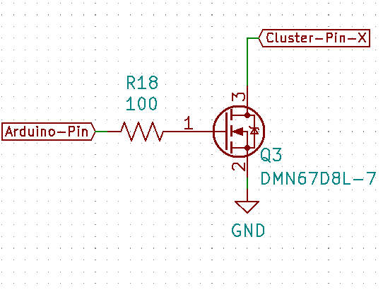
This circuit in essence acts like a switch: When the Arduino applies 5V to the input of the circuit, the MOSFET (the DMN67D8L-7 part) turn on, and pulls the cluster pin to ground. The current that flows in this case can be up to 30mA, so the part was selected so that it could handle at least this (the selected part can handle up to roughly 200 mA). If the Arduino applies 0V to the input of the circuit, the MOSFET turns off and the cluster pin is pulled back up to 12V.
This circuit is used to control the following pins:
X11175 Connector: 13, 17, 19, 20, 21, 22, 23, 24, 26
X11176 Connector: 4, 5, 6, 7, 12, 13
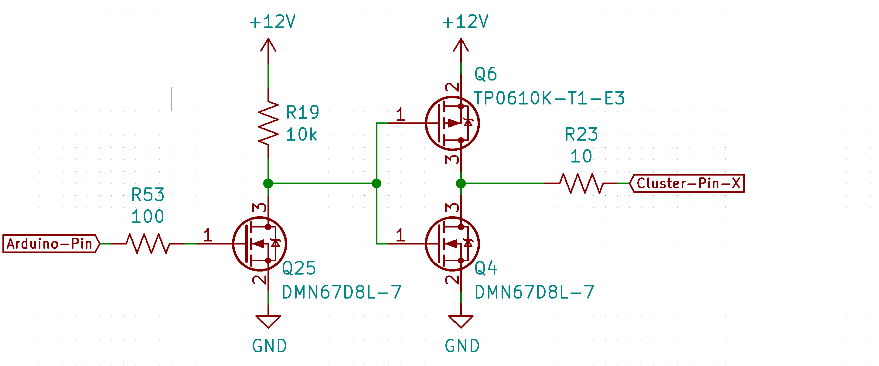
This circuit acts very similar to the basic pull-down network: If the Arduino applies 5V on the input of the circuit, Q6 will turn on (connect the cluster pin to 12V), and Q4 will turn off. If the Arduino applies 0V on the input of the circuit, Q6 will turn off, and Q4 will turn on (connect the cluster pin to ground). The 10 Ohm resistor was added to limit the current going into the pin the circuit is connected to.
This circuit is used to control the following pins: X11175 Connector: 2, 7 X11176 Connector: 14
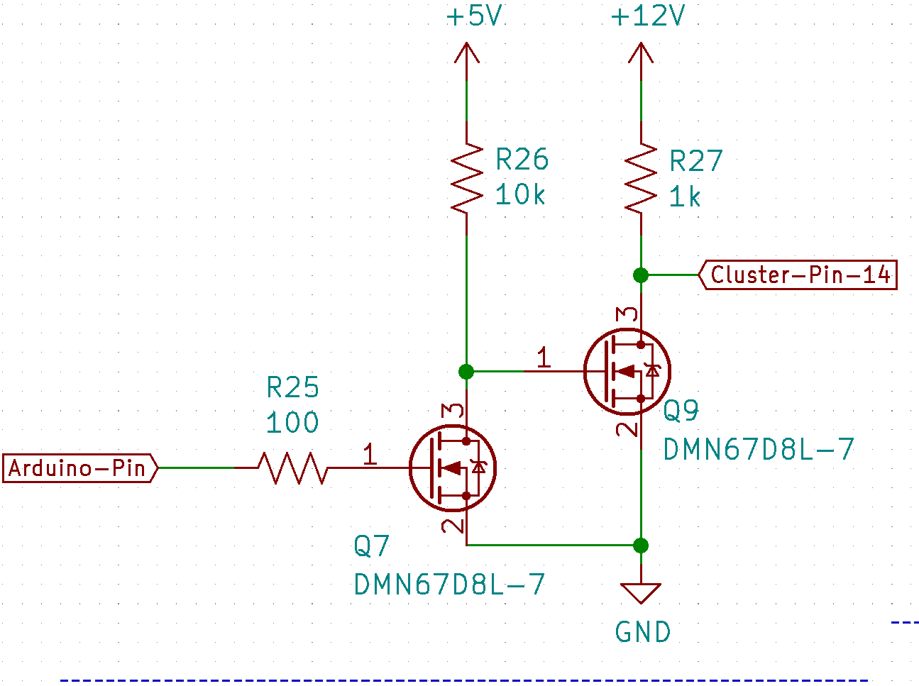
When the Arduino applies 0V to this circuit, Q7 turns off, and pulls the gate of Q9 up to 5V. This turns on Q9, and thus applies 0V to cluster pin 14. When the Arduino applies 5V to this circuit, Q7 turns on, and pulls the gate of Q9 down to ground. This turns off Q9, and thus pulls cluster pin 14 up to 12V. This circuit is used to translate the 5V 'Serial' messages coming from the Arduino to 12V message signals that the cluster expects to see.
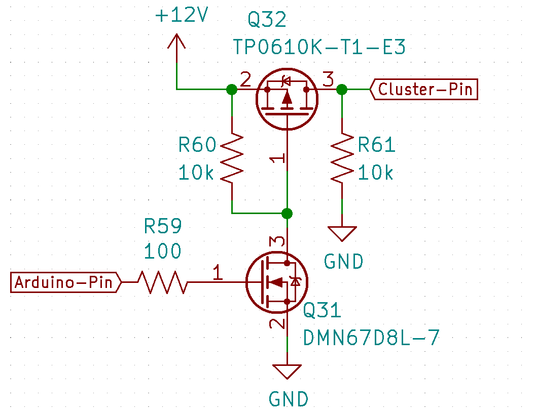
When the Arduino applies 5V to this circuit, it turns on Q31, which then pulls the gate of Q32 down to ground. Q32 is a PMOS transistor, and thus this turns the FET 'ON' which then applies 12V to the cluster pin. When the Arduino applies 0V to this circuit, it turns Q31 off, which then pulls the gate of Q32 up to 12V. This turns the FET 'OFF' which then pulls the cluster pin down to ground.
This circuit was used to control the ignition and accessory mode cluster pins (X11175 pins 5 and 6 respectively)

This circuit is a direct copy of the circuit used on the MCP2515 SPI to CAN development boards, such as this one:
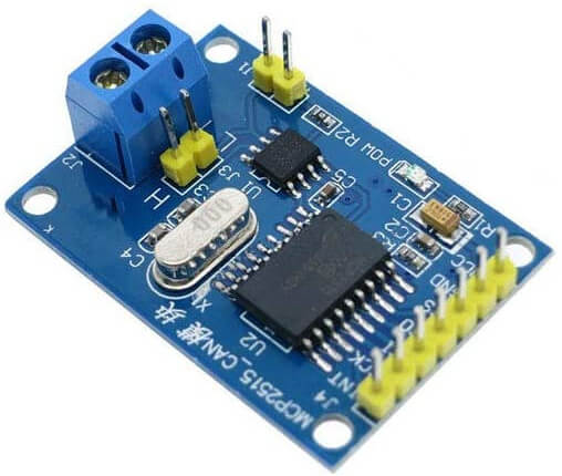
This circuit is known more commonly as a 'shunt-regulator' (similar to the popular TL431 part you can find available online). This circuit makes more sense when you consider what the circuit on the input of the cluster looks like for X11175 Pins 11 and 15 (Tank1+ and Tank2+ respectively):
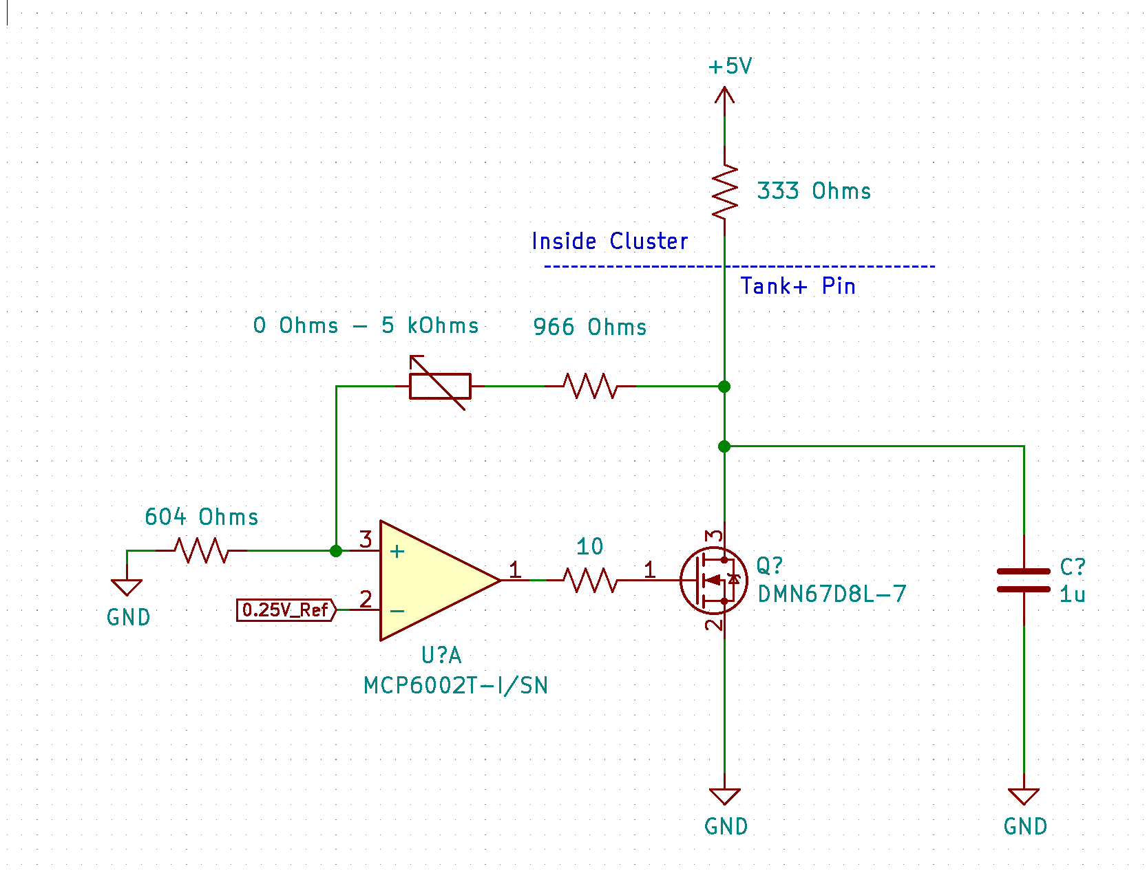
In this more simplified circuit, I represent the digital potentiometer as a normal potentiometer, and show what the input of the cluster looks like for the Tank+ pins. The idea is that as we change the value of the potentiometer, the gain of the circuit changes and causes the voltage at the Tank+ pin to change accordingly.
For example:
If the potentiometer is set to 0 ohms, the tank+ pin will be set to roughly 0.65V. To the cluster, this would look just the same as connecting a 50 Ohm resistor from the pin to ground. In the case that the potentiometer is set to 5kOhms, the voltage at the take+ pin will be set to roughly 2.7 Volts, which looks just the same as if a 397 Ohms resistor was connected from the pin to ground.
In this sense, the circuit acts as a variable resistor that we can set from the Arduino ranging between about 50 Ohms and 397 Ohms, which covers the normal operating range for this pin of a resistance value between 70 Ohms and 395 Ohms (see table above for tank+ pins). In theory, the same circuit could have also been used for the ambient temperature sensor, but I chose against this since it did not change system performance at all.
There are a few circuits in the design containing connectors, DIP switches, and other such items that I do not cover here as they are more self-explanatory, but if you would like to know about any other part of of the schematic design, please let me know.
For this project, I provided two main programs: E46_Cluster_Test, and main-simhub-code. The following section outlines these two programs, as well as the communication protocol that is common to both programs:
This program was created in order to perform basic tests on the cluster. After uploading this code, you can send commands from the serial monitor to the Arduino, and then the Arduino will interact with the cluster in order to carry out the desired function. You must send every command with the following syntax:

In addition, make sure the Arduino Serial monitor is setup as shown below (most importantly, have the baud rate set to 9600, and the line ending set to 'Newline'):

See the section Valid Command / Argument Combos for both programs for a list of commands that you can send to the cluster, along with the effect each one has.
This program was created in order to interface with the cluster through the computer software SimHub, which allows you to send data from racing games to an Arduino. This program receieves data from SimHub, and using the same methods as the E46_Cluster_Test program, sets the cluster up to reflect the sent data. You have to upload this program to the Arduino before attempting to use the SimHub application, or else it will hijack the serial port and not let you program the Arduino until you close the application.
In order to make this application work with the hardware, you need to do the following:
At this point, you should be able to launch games from the SimHub dashboard (ensure that you configure each game according to SimHub's instructions).
The following is a list of valid commands and arguments that you can send to the instrument cluster from both applications. You can send these commands directly through the serial monitor for the E46_Cluster_Test program, or through a Custom Protocol in SimHub:
| Command | Valid Arguments | Description |
|---|---|---|
| speed | Integer between 1 and 163 | Sets the speedometer to the desired value in MPH |
| rpm | Integer between 0 and 7000 | Sets the tachometer to the desired value in RPM |
| temp | Integer between 65 and 405 | Sets the oil temperature gauge to the desired value in degrees celcius |
| ignition | Either 1 or 0 | Turns the ignition state to on / off |
| accessory | Either 1 or 0 | Turns the accessory state to on / off |
| fuel | Integer between 1 and 100 | Sets the fuel gauge to the desired value (have to cycle 12V power to cluster to change immediately) |
| engineStateFeedback | Either 1 or 0 | No noticeable effect |
| signalGong | Either 1 or 0 | No noticeable effect |
| bc_button | Either 1 or 0 | No noticeable effect |
| seatBelt | Either 1 or 0 | No noticeable effect |
| coolantLevelSensor | Either 1 or 0 | '0' causes the coolant light to come on, '1' turns it off (have to cycle ignition to change state) |
| brakeWearSensor | Either 1 or 0 | '0' causes the brake pad wear light to come on, '1' turns it off |
| parkingBrakeState | Either 1 or 0 | '0' turns BRAKE light on, '1' turns it off |
| ABS_Warning | Either 1 or 0 | '0' turns ABS light on, '1' turns it off |
| airbagLight | Either 1 or 0 | '0' turns airbag light off, '1' turns it on |
| brakeFluidSensor | Either 1 or 0 | No noticeable effect |
| oilSensor | Either 1 or 0 | No noticeable effect |
| oilPressureSwitch | Either 1 or 0 | No noticeable effect |
| clusterBacklight | Either 1 or 0 | No noticeable effect |
| washerFluidLight | Either 1 or 0 | '1' turns the light off, '0' turns it on (have to cycle ignition to change |
| cruiseLight | Either 1 or 0 | |
| rolloverSensor | Either 1 or 0 | |
| reverse | Either 1 or 0 | |
| eLight | Either 1 or 0 | '1' turns the Service Engine Soon light on, '0' turns off |
| emlLight | Either 1 or 0 | '1' turns the EML light on, '0' turns off |
| gasCapLight | Either 1 or 0 | '1' turns the CHECK GAS CAP light on, '0' turns off |
| heatLight | Either 1 or 0 | '1' turns the over temperature light on, '0' turns off |
| oilLight | Either 1 or 0 | '1' turns the low oil pressure warning light on, '0' turns it off |
| chgLight | Either 1 or 0 | '1' turns the battery charge light on, '0' turns it off |
| highBeam | Either 1 or 0 | '1' turns the highbeam indicator on, '0' turns it off |
| fogRear | Either 1 or 0 | '1' turns the rear fog-light indicator on, '0' turns it off |
| fogFront | Either 1 or 0 | '1' turns the front fog-light indicator on, '0' turns it off |
| leftBlink | Either 1 or 0 | '1' turns the left blinker on, '0' turns it off |
| rightBlink | Either 1 or 0 | '1' turns the right blinker on, '0' turns it off |
| backRightLight | Either 1 or 0 | '1' turns the light on, '0' turns it off |
| backLeftLight | Either 1 or 0 | '1' turns the light on, '0' turns it off |
| frontRightLight | Either 1 or 0 | '1' turns the light on, '0' turns it off |
| frontLeftLight | Either 1 or 0 | '1' turns the light on, '0' turns it off |
| carLight | Either 1 or 0 | '1' turns the light on, '0' turns it off |
| Qty | Value | Footprint | References |
|---|---|---|---|
| 27 | DMN67D8L-7 | Package_TO_SOT_SMD:SOT-23 | Q1, Q2, Q10, Q11, Q12, Q13, Q14, Q15, Q16, Q17, Q18, Q19, Q20, Q21, Q22, Q23 +11 |
| 21 | 100 | Resistor_SMD:R_0603_1608Metric | R18, R25, R28, R29, R30, R31, R32, R33, R34, R35, R36, R37, R38, R39, R40, R41 +5 |
| 21 | 10k | Resistor_SMD:R_0603_1608Metric | R1, R2, R16, R19, R20, R26, R43, R45, R46, R47, R48, R49, R50, R51, R52, R55 +5 |
| 5 | 0.1u | Capacitor_SMD:C_0805_2012Metric | C3, C6, C7, C8, C9 |
| 5 | 10 | Resistor_SMD:R_0603_1608Metric | R11, R12, R23, R24, R44 |
| 5 | Conn_01x08_Female | Connector_PinSocket_2.54mm:PinSocket_1x08_P2.54mm_Vertical | J1, J2, J3, J6, J7 |
| 5 | TP0610K-T1-E3 | Package_TO_SOT_SMD:SOT-23 | Q6, Q8, Q27, Q30, Q32 |
| 2 | 1k | Resistor_SMD:R_0603_1608Metric | R3, R27 |
| 2 | 1u | Capacitor_SMD:C_0805_2012Metric | C1, C2 |
| 2 | 22p | Capacitor_SMD:C_0603_1608Metric | C4, C5 |
| 2 | 604 | Resistor_SMD:R_0603_1608Metric | R14, R15 |
| 2 | 966 | Resistor_SMD:R_0603_1608Metric | R9, R10 |
| 2 | Conn_01x09 | Connector_PinHeader_2.54mm:PinHeader_1x09_P2.54mm_Vertical | J11, J12 |
| 2 | Conn_01x13 | Connector_PinHeader_2.54mm:PinHeader_1x13_P2.54mm_Vertical | J10, J13 |
| 1 | 100k | Resistor_SMD:R_0603_1608Metric | R22 |
| 1 | 120 | Resistor_SMD:R_0603_1608Metric | R17 |
| 1 | 200k | Resistor_SMD:R_0603_1608Metric | R21 |
| 1 | 8 MHz | # Custom Crystals:Crystal_SMD_5032-4Pin_5.0x3.2mm | Y1 |
| 1 | 90.9k | Resistor_SMD:R_0603_1608Metric | R5 |
| 1 | Conn_01x10_Female | Connector_PinSocket_2.54mm:PinSocket_1x10_P2.54mm_Vertical | J5 |
| 1 | Conn_02x09_Top_Bottom | # Custom Connectors (2.00 mm):PinHeader_2x09_P2.00mm_Vertical_SMD_Top_Bottom;98424-G52-18ALF | J9 |
| 1 | Conn_02x13_Top_Bottom | # Custom Connectors (2.54 mm):3020-26-0300-00 | J8 |
| 1 | Conn_02x18_Odd_Even | Connector_PinSocket_2.54mm:PinSocket_2x18_P2.54mm_Vertical | J4 |
| 1 | MCP2515-xSO | Package_SO:SOIC-18W_7.5x11.6mm_P1.27mm | U5 |
| 1 | MCP4251-xxxx-ST | Package_SO:TSSOP-14_4.4x5mm_P0.65mm | U1 |
| 1 | MCP6002T-I/SN | Package_SO:SOIC-8_3.9x4.9mm_P1.27mm | U4 |
| 1 | SW_DIP_x04 | Button_Switch_SMD:SW_DIP_SPSTx04_Slide_9.78x12.34mm_W8.61mm_P2.54mm | SW2 |
| 1 | SW_MEC_5E | Button_Switch_SMD:SW_SPST_Omron_B3FS-101xP | SW1 |
| 1 | SolderJumper_2_Open | Jumper:SolderJumper-2_P1.3mm_Open_Pad1.0x1.5mm | JP1 |
| 1 | TJA1050T-3 | Package_SO:SOIC-8_3.9x4.9mm_P1.27mm | U6 |
| 1 | TL431DBZ | Package_TO_SOT_SMD:SOT-23 | U2 |


festlv/mso5000-logic-probe
Cheap logic probe for Rigol MSO5000-series oscilloscopes

OpenSourceNeuro/Spikeling
A hardware implementation of spiking neurons for neuroscience teaching and outreach


It measures 101.6 × 53.3 mm and has 2 copper layers, 1.6 mm thick.
120 parts, built around the MCP6002T-I/SN(MS), DMN67D8L-7 and TP0610K-T1-E3. The full list of its parts is on this page, with links to each part's symbol and footprint where PCBKit's library has them.
From the KSullivan20221/SimHub-BMW-E46-Cluster-Module repository on GitHub, at the commit this page was made from: the board is KiCAD Project/BMW E46 Cluster Interface Board.kicad_pcb. PCBKit opens the board in the browser, with nothing to install.
Its repository states no licence, so its author keeps all rights: ask KSullivan20221 before reusing the design.