
2 layers37 × 40.5 mm
ATtiny85-LEDs
JeremySCook/ATtiny85-5LEDPCB
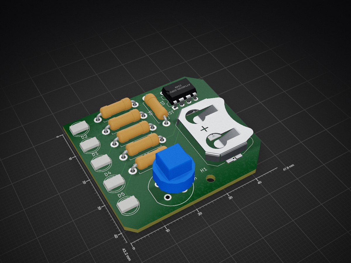
PCB with 5 LEDs, different blinking routines for each.
15 parts1
 JeremySCook/ATtiny85-5LEDPCB1
PCB with 5 LEDs, different blinking routines for each.
ATtiny85-LEDs is an open-source printed circuit board by JeremySCook, from the JeremySCook/ATtiny85-5LEDPCB repository on GitHub. It is a 2-layer board of 47.6 × 43.2 mm with 15 parts on 13 nets, routed with 56 tracks and 3 vias.
It is built around the ATTINY85-20PU. Its parts include 6 resistors, 5 diodes, 1 IC and 1 switch. It belongs with the AVR (ATmega, ATtiny) boards of this library.
KiCAD files for new version using SMD components that activates based on bike wheel's rotation.
Works, but could be improved. ICSP header is connected incorrectly, and battery life is somewhat unknown.
| Qty | Value | Footprint | References |
|---|---|---|---|
| 5 | 50R | Resistor_THT:R_Axial_DIN0411_L9.9mm_D3.6mm_P12.70mm_Horizontal | R1, R2, R3, R4, R5 |
| 5 | LED | LED_THT:LED_D5.0mm | D1, D2, D3, D4, D5 |
| 1 | 10k | Resistor_THT:R_Axial_DIN0411_L9.9mm_D3.6mm_P12.70mm_Horizontal | R6 |
| 1 | ATtiny85-20PU | Package_DIP:DIP-8_W7.62mm | U1 |
| 1 | CR2032Bat | Battery:BatteryHolder_Keystone_3034_1x20mm | B1 |
| 1 | MountingHole | MountingHole:MountingHole_2.5mm | H1 |
| 1 | SW_Push_Dual | Button_Switch_THT:Push_E-Switch_KS01Q01 | SW1 |
JeremySCook/ATtiny85-5LEDPCB
PCB with 5 LEDs, different blinking routines for each.

bwack/C64-Switchless-Multi-Kernal-27C256-adapter
Kernal switcher for the C64/C64C/C128

plusvic/simplebus2-intercom
General description of the Simplebus2 protocol used by some Comelit's intercoms. Hardware for retransmitting Simplebus2 messages over UART.

osmocom/osmocom-analog
Software Implementation of analog cellular telephony systems like NMT, TACS, IMTS, A/B/C-Netz; mirror of https://gitea.osmocom.org/cellular-infrastructure/osmocom-analog

strickyak/jerboa-attiny85-mod-synth
Modular Synthesizer using an ATtiny85 chip for each module.


Hack-a-Day/Remoticon_KiCad_Blender
support files for the 2020 Remoticon KiCad to Blender > PCB renders workshop

It measures 47.6 × 43.2 mm and has 2 copper layers, 1.6 mm thick.
15 parts, built around the ATTINY85-20PU. The full list of its parts is on this page, with links to each part's symbol and footprint where PCBKit's library has them.
From the JeremySCook/ATtiny85-5LEDPCB repository on GitHub, at the commit this page was made from: the board is 5LEDKiCad/ATtiny85-LEDs.kicad_pcb. PCBKit opens the board in the browser, with nothing to install.
Its repository states no licence, so its author keeps all rights: ask JeremySCook before reusing the design.