6 layers120 × 50 mm
Usb switch
cubicap/usb4-thing
An attemt at creating a USB4 multiplexer controlled by ESP32-S3.
65 parts

 JaronCyna/sat_mppt_pcb
Maximum Power Point Tracking board meant for use in the QSET 3U CubeSat
EPS mppt board is an open-source printed circuit board by JaronCyna, from the JaronCyna/sat_mppt_pcb repository on GitHub. It is a 6-layer board of 90.2 × 95.9 mm with 287 parts on 317 nets, routed with 2,997 tracks and 671 vias.
It is built around the TCAN337GD, MR20H40DF and LTC4417HUF#PBF, with the TPS3823A-33DBVR, M80-5400642 and SIR5607DP-T1-RE3 among its other parts. Its parts include 110 capacitors, 108 resistors, 19 ICs, 15 transistors and 13 diodes. It belongs with the STM32 boards of this library.


A flight-ready 4-channel distributed Maximum Power Point Tracking (MPPT) battery charging and power distribution board designed in KiCad for CubeSat nanosatellite missions. Engineered for the Queen's Space Engineering Team (QSET) satellite branch.
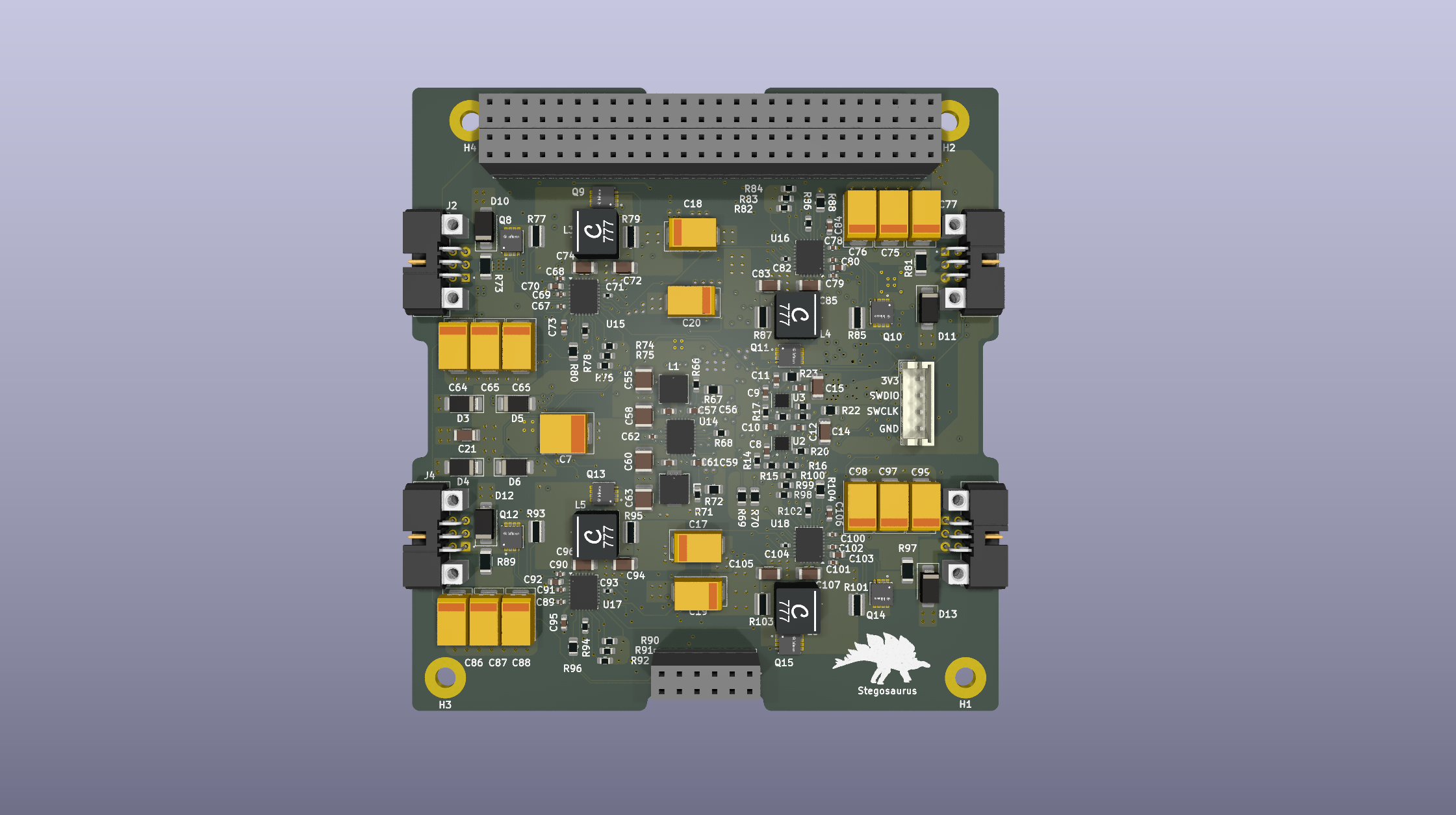
| Top Layer (Switching & Hot Loops) | Bottom Layer (Routing & Ground Shield) |
|---|---|
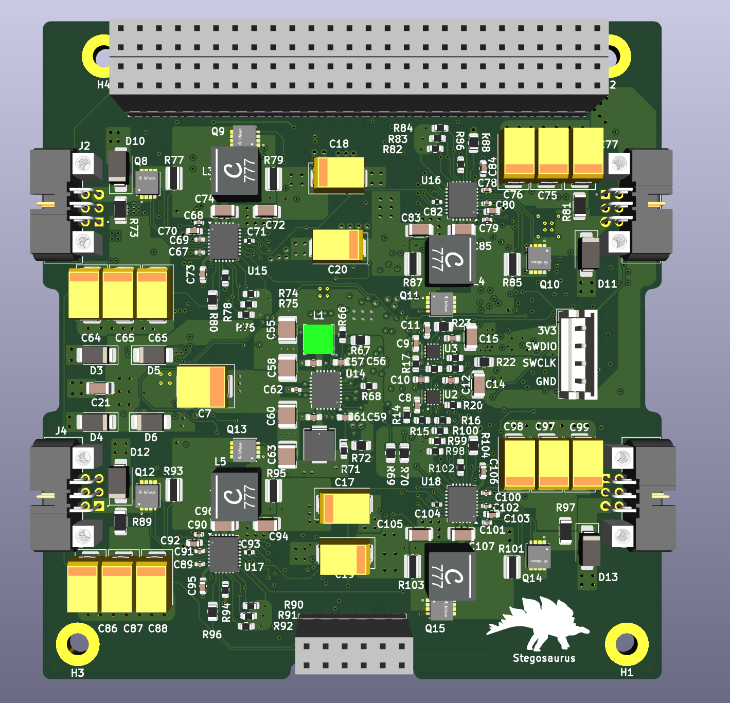 | 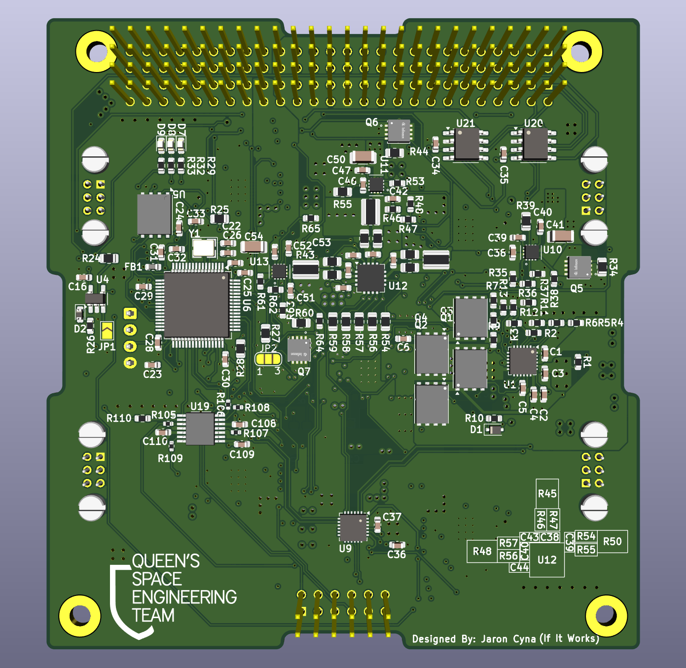 |
| Parameter | Specification / Value | Engineering Notes |
|---|---|---|
| Solar Input Channels | 4 independent MPPT channels | 1 channel per satellite face (up to ~18V $V_{\text{oc}}$ per string) |
| Battery Bus Configuration | 2S Li-ion (6.0V – 8.4V) | Direct autonomous CC/CV charging |
| MPPT Switching Frequency | 1.5 MHz (Synchronized) | Phase-locked via MCU PWM buffer to eliminate beat frequencies |
| +3.3V Regulated Bus | 3.3V @ 3A max (<15 mV ripple) | Generated by LTC3633 monolithic buck; eFuse clamped at 1.33A |
| +5.0V Regulated Bus | 5.0V @ 3A max (<15 mV ripple) | Generated by LTC3633 monolithic buck |
| Telemetry Storage | 4 MB SPI MRAM | Immune to SEU and TID radiation effects in LEO |
| Bus Interfaces | Dual CAN Bus + I2C | Redundant CubeSat standard bus communication |
| PCB Stackup | 6-Layer FR4 (1.6mm) | Top: Switching, L2: GND, L3: Mix, L4: Mix, L5: GND, L6: Digital |
| Mechanical Standard | PC/104 CubeSat Standard | Custom battery interface with Kelvin sense + NTC |
Each regulated rail is protected by a TI TPS25947 eFuse and monitored by a TI INA3221 current/voltage telemetry IC:
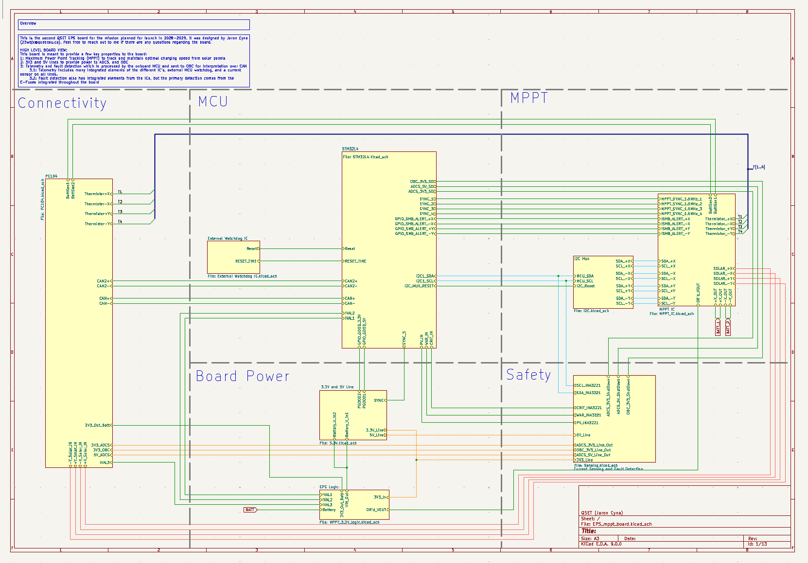
The hardware schematic is split into modular hierarchical sheets:
| Schematic Sheet | Description | Primary Components |
|---|---|---|
EPS_mppt_board.kicad_sch | Root top-level hierarchical sheet | Interconnects and top-level bus routing |
MPPT_IC.kicad_sch | Quad MPPT top-level sheet | 4x instances of MPPT_indv.kicad_sch |
MPPT_indv.kicad_sch | Single-channel MPPT buck charger | LTC4162, power inductors, input/output caps |
3.3V.kicad_sch | Dual synchronous buck converter | LTC3633 (generates +3.3V and +5.0V rails) |
MPPT_3.3V_logic.kicad_sch | Power-path and bootstrapping | LTC4412 Ideal Diode Controller |
Sensing.kicad_sch | Power telemetry and fault protection | INA3221 monitor, TPS25947 eFuses |
STM32L4.kicad_sch | Microcontroller, MRAM, and clocking | STM32L496, 4MB MRAM, 4-pin OSC, 1:6 PWM buffer |
I2C.kicad_sch | I2C bus multiplexer | TCA9548A 8-channel I2C switch |
External Watchdog IC.kicad_sch | Deterministic hardware supervisor | TPS3823A watchdog IC + Schottky pull-up |
PC104.kicad_sch | Satellite bus interface & connectors | PC/104 bus header, battery Kelvin sense, solar inputs |
Sat_MPPT_PCB/
├── .gitignore                      # Standard KiCad ignore rules
├── README.md                       # Board documentation and specifications
│
├── docs/                           # Documentation & exports
│   ├── bom/
│   │   └── EPS_mppt_board.csv      # Complete Bill of Materials
│   ├── pdf/
│   │   └── EPS_mppt_board.pdf      # Complete schematic PDF
│   └── svg/                        # Exported vector schematics per sheet
│       ├── EPS_mppt_board.svg
│       ├── EPS_mppt_board-3.3V Logic.svg
│       ├── EPS_mppt_board-MPPT IC.svg
│       └── ...
│
├── scripts/                        # Simulation & analysis tools
│   └── mppt_efficiency_sim.py      # 4-MPPT vs 1-MPPT orbital comparison simulation
│
├── archive/                        # Early design prototypes and iterations
│   └── prototypes/
│
├── 3D_Models/                      # 3D STEP/STP component models
│
├── sym-lib-table # KiCad Symbol Library TableSwitching & Transient Simulations: LTspice models verified buck converter stability, hot-loop parasitic response, and transient load step response (0.1A to 3.0A step with <15 mV voltage deviation).
SPICE: All IC's with available SPICE models were simullated in PSPICE or LTSPICE.
| Qty | Value | Footprint | References |
|---|---|---|---|
| 24 | 10k | Resistor_SMD:R_0805_2012Metric | R22, R23, R24, R25, R27, R28, R34, R39, R44, R54, R55, R56, R57, R58, R59, R104 +8 |
| 19 | 100n | Capacitor_SMD:C_0603_1608Metric | C16, C24, C25, C27, C28, C29, C30, C31, C32, C34, C35, C37, C56, C108, C109, C110 +3 |
| 16 | 47 uF | Capacitor_Tantalum_SMD:CP_EIA-7343-43_Kemet-X | C17, C18, C19, C20, C64, C65, C66, C75, C76, C77, C86, C87, C88, C97, C98, C99 |
| 13 | 100k | Resistor_SMD:R_0603_1608Metric | R11, R12, R13, R16, R19, R20, R21, R37, R38, R48, R53, R63, R64 |
| 11 | 100nF | Capacitor_SMD:C_0603_1608Metric | C1, C2, C3, C4, C8, C9, C38, C42, C48, C49, C51 |
| 11 | Q_NMOS | zLibrary:IFX-PG-TSDSON-8-44-V | Q5, Q6, Q7, Q8, Q9, Q10, Q11, Q12, Q13, Q14, Q15 |
| 9 | 10 uF | Capacitor_SMD:C_1206_3216Metric | C21, C72, C74, C83, C85, C94, C96, C105, C107 |
| 8 | 100n | Capacitor_SMD:C_0402_1005Metric | C67, C69, C78, C80, C89, C91, C100, C102 |
| 8 | 10m | Resistor_SMD:R_0612_1632Metric | R77, R79, R85, R87, R93, R95, R101, R103 |
| 8 | 4.7k | Resistor_SMD:R_0603_1608Metric | R74, R75, R82, R83, R90, R91, R98, R99 |
| 6 | 10 | Resistor_SMD:R_0805_2012Metric | R41, R42, R49, R50, R51, R52 |
| 5 | 100pF | Capacitor_SMD:C_0603_1608Metric | C12, C13, C40, C47, C53 |
| 5 | 10k | Resistor_SMD:R_0603_1608Metric | R76, R84, R92, R100, R110 |
| 5 | 10uF | Capacitor_SMD:C_1206_3216Metric | C14, C15, C41, C50, C54 |
| 5 | 1uF | Capacitor_SMD:C_0603_1608Metric | C5, C33, C43, C44, C45 |
| 5 | 2.2nF | Capacitor_SMD:C_0603_1608Metric | C10, C11, C39, C46, C52 |
| 5 | 33 | Resistor_SMD:R_0402_1005Metric | R105, R106, R107, R108, R109 |
| 5 | TPS259470ARPWR | zLibrary:RPW0010A-MFG | U2, U3, U10, U11, U13 |
| 4 | 1 uF | Capacitor_SMD:C_0603_1608Metric | C73, C84, C95, C106 |
| 4 | 100n | Resistor_SMD:R_0402_1005Metric | C71, C82, C93, C104 |
| 4 | 182k | Resistor_SMD:R_0603_1608Metric | R14, R17, R35, R46 |
| 4 | 2.5 | Resistor_SMD:R_1206_3216Metric | R73, R81, R89, R97 |
| 4 | 20k | Resistor_SMD:R_0603_1608Metric | R15, R18, R36, R47 |
| 4 | 22nF | Capacitor_SMD:C_0402_1005Metric | C68, C79, C90, C101 |
| 4 | 22uF | Capacitor_SMD:C_1210_3225Metric | C55, C58, C60, C63 |
| 4 | 4.7 uF | Capacitor_SMD:C_0603_1608Metric | C70, C81, C92, C103 |
| 4 | 4.7uH | zLibrary:XAL6060472MEC | L3, L4, L5, L6 |
| 4 | 63.4k | Resistor_SMD:R_0603_1608Metric | R78, R86, R94, R102 |
| 4 | D_Schottky | Diode_SMD:D_SOD-128 | D3, D4, D5, D6 |
| 4 | LTC4162IUFD-LADM_PBF | Package_DFN_QFN:QFN-28-1EP_4x5mm_P0.5mm_EP2.65x3.65mm_ThermalVias | U15, U16, U17, U18 |
| 4 | M80-5400642 | zLibrary:HARWIN_M80-5400642 | J2, J3, J4, J5 |
| 4 | MountingHole_Pad | MountingHole:MountingHole_3.2mm_M3_Pad | H1, H2, H3, H4 |
| 4 | SIR5607DP-T1-RE3 | Package_SO:PowerPAK_SO-8_Single | Q1, Q2, Q3, Q4 |
| 4 | SMAJ22A | Diode_SMD:D_SMA | D10, D11, D12, D13 |
| 3 | 1M | Resistor_SMD:R_0603_1608Metric | R1, R4, R7 |
| 3 | 330 | Resistor_SMD:R_0603_1608Metric | R29, R32, R33 |
| 3 | 4m | Resistor_SMD:R_0815_2038Metric | R40, R43, R45 |
| 2 | 10pF | Capacitor_SMD:C_0603_1608Metric | C22, C26 |
| 2 | ESQ-126-39-G-D | zLibrary:SAMTEC_ESQ-126-39-G-D | J6, J7 |
| 2 | TCAN337G | Package_SO:SOIC-8_3.9x4.9mm_P1.27mm | U20, U21 |
| 1 | 0 | Resistor_SMD:R_0603_1608Metric | R26 |
| 1 | 1 uH | zLibrary:IND_PA4332_PUL-M | L1 |
| 1 | 1.5 uH | zLibrary:IND_SRP4020_BRN-M | L2 |
| 1 | 10 uF | Capacitor_SMD:C_0603_1608Metric | C36 |
| 1 | 100uF | Capacitor_Tantalum_SMD:CP_EIA-7361-38_AVX-V | C7 |
| 1 | 140k | Resistor_SMD:R_0603_1608Metric | R6 |
| 1 | 2.2 uF | Capacitor_SMD:C_0402_1005Metric | C62 |
| 1 | 2.21k | Resistor_SMD:R_0603_1608Metric | R10 |
| 1 | 215k | Resistor_SMD:R_0603_1608Metric | R68 |
| 1 | 31.6k | Resistor_SMD:R_0603_1608Metric | R62 |
| 1 | 348k | Resistor_SMD:R_0603_1608Metric | R61 |
| 1 | 4.7uF | Capacitor_SMD:C_0603_1608Metric | C23 |
| 1 | 412k | Resistor_SMD:R_0603_1608Metric | R9 |
| 1 | 45.3k | Resistor_SMD:R_0603_1608Metric | R66 |
| 1 | 52.3k | Resistor_SMD:R_0603_1608Metric | R3 |
| 1 | 57.6k | Resistor_SMD:R_0603_1608Metric | R2 |
| 1 | 5k | Resistor_SMD:R_0603_1608Metric | R65 |
| 1 | 6.8nF | Capacitor_SMD:C_0603_1608Metric | C6 |
| 1 | 60.4k | Resistor_SMD:R_0603_1608Metric | R5 |
| 1 | 600 ohms @ 100MHz | Inductor_SMD:L_0603_1608Metric | FB1 |
| 1 | 73.2k | Resistor_SMD:R_0603_1608Metric | R71 |
| 1 | 8 MHZ Oscillator | Crystal:Crystal_SMD_3225-4Pin_3.2x2.5mm | Y1 |
| 1 | 82.5k | Resistor_SMD:R_0603_1608Metric | R8 |
| 1 | BAT54J | Diode_SMD:D_SOD-323F | D1 |
| 1 | Blue LED | LED_SMD:LED_0603_1608Metric | D9 |
| 1 | Conn_01x04_Pin | Connector_JST:JST_EH_B4B-EH-A_1x04_P2.50mm_Vertical | J1 |
| 1 | D_Schottky | Diode_SMD:D_0603_1608Metric | D2 |
| 1 | ESQ-106-39-G-D | zLibrary:SAMTEC_ESQ-106-39-G-D | J8 |
| 1 | Green LED | LED_SMD:LED_0603_1608Metric | D8 |
| 1 | INA3221 | Package_DFN_QFN:Texas_RGV0016A_VQFN-16-1EP_4x4mm_P0.65mm_EP2.1x2.1mm | U12 |
| 1 | LMK1C1106PWR | zLibrary:PW0014A-IPC_B | U19 |
| 1 | LTC3633AIUFDPBF | Package_DFN_QFN:QFN-28-1EP_4x5mm_P0.5mm_EP2.65x3.65mm_ThermalVias | U14 |
| 1 | LTC4417HUF | Package_DFN_QFN:QFN-24-1EP_4x4mm_P0.5mm_EP2.6x2.6mm | U1 |
| 1 | MR20H40 | Package_DFN_QFN:DFN-8-1EP_6x5mm_P1.27mm_EP4x4mm | U5 |
| 1 | Red LED | LED_SMD:LED_0603_1608Metric | D7 |
| 1 | STM32L496RGTx | Package_QFP:LQFP-64_10x10mm_P0.5mm | U6 |
| 1 | S_Jumper | Jumper:SolderJumper-2_P1.3mm_Open_TrianglePad1.0x1.5mm | JP1 |
| 1 | SolderJumper | Jumper:SolderJumper-3_P1.3mm_Open_RoundedPad1.0x1.5mm_NumberLabels | JP2 |
| 1 | TCA9548AMRGER | Package_DFN_QFN:Texas_RGE0024C_VQFN-24-1EP_4x4mm_P0.5mm_EP2.1x2.1mm | U9 |
| 1 | TPS3823A-33DBVR | Package_TO_SOT_SMD:SOT-23-5_HandSoldering | U4 |
cubicap/usb4-thing
An attemt at creating a USB4 multiplexer controlled by ESP32-S3.

kenchangh/kensat
KENSAT, Edge-AI Compute in Orbit - A 2U CubeSat that runs a large language model on-orbit. A power-gated NVIDIA Jetson Orin Nano executes neural-network inference in space, and the results are downlinked over a custom…

macnetic/rp2040-cubesat
A CubeSat Onboard Computer, using the RP2040 microcontroller.

mawson-rovers/hestia
Hestia is a space-ready heater & temperature measurement system developed by Mawson Rovers in Sydney. Its first mission will demonstrate a novel UTS heatsink design, aboard the Waratah Seed cubesat mission.

ngrabbs/ember
Open pvpanel.kicadpro with KiCad 10. The project contains the recovered schematic, routed PCB, project-local footprint libraries, and solar-module STEP model.


UChicago-Space-Program/pulse-hardware
This is the central repository for documents related to PULSE-A hardware development.
It measures 90.2 × 95.9 mm and has 6 copper layers, 1.6 mm thick.
287 parts, built around the TCAN337GD, MR20H40DF, LTC4417HUF#PBF and TPS3823A-33DBVR. The full list of its parts is on this page, with links to each part's symbol and footprint where PCBKit's library has them.
From the JaronCyna/sat_mppt_pcb repository on GitHub, at the commit this page was made from: the board is EPS_mppt_board.kicad_pcb and its schematic 3.3V.kicad_sch. PCBKit opens the board in the browser, with nothing to install.
Its repository states no licence, so its author keeps all rights: ask JaronCyna before reusing the design.